Symbol Technologies PDT7533 PDT7533 Portable Data Terminal User Manual 72 38888 02a
Symbol Technologies Inc PDT7533 Portable Data Terminal 72 38888 02a
users manual

PDT 7500 Series
PRELIMINARY

PDT 7500 Series
1999-2000 SYMBOL TECHNOLOGIES, INC. All rights reserved.
Symbol reserves the right to make changes to any product to improve reliability,
function, or design.
Symbol does not assume any product liability arising out of, or in connection with, the
application or use of any product, circuit, or application described herein.
No license is granted, either expressly or by implication, estoppel, or otherwise under
any patent right or patent, covering or relating to any combination, system, apparatus,
machine, material, method, or process in which Symbol products might be used. An
implied license only exists for equipment, circuits, and subsystems contained in Symbol
products.
Symbol is a registered trademark of Symbol Technologies, Inc. Other product names
mentioned in this manual may be trademarks or registered trademarks of their
respective companies and are hereby acknowledged.
Symbol Technologies, Inc.
One Symbol Plaza
Holtsville, N.Y. 11742-1300
http://www.symbol.com
Patents
This product is covered by one or more of the following U.S. and foreign Patents:
U.S. Patent No.4,387,297; 4,460,120; 4,496,831; 4,593,186; 4,603,262; 4,607,156;
4,652,750; 4,673,805; 4,736,095; 4,758,717; 4,816,660; 4,845,350; 4,896,026;
4,897,532; 4,923,281; 4,933,538; 4,992,717; 5,015,833; 5,017,765; 5,021,641;
5,029,183; 5,047,617; 5,103,461; 5,113,445; 5,130,520; 5,140,144; 5,142,550;
5,149,950; 5,157,687; 5,168,148; 5,168,149; 5,180,904; 5,216,232; 5,229,591;
5,230,088; 5,235,167; 5,243,655; 5,247,162; 5,250,791; 5,250,792; 5,260,553;
5,262,627; 5,262,628; 5,266,787; 5,278,398; 5,280,162; 5,280,163; 5,280,164;
5,280,498; 5,304,786; 5,304,788; 5,306,900; 5,321,246; 5,324,924; 5,337,361;
5,367,151; 5,373,148; 5,378,882; 5,396,053; 5,396,055; 5,399,846; 5,408,081;
5,410,139; 5,410,140; 5,412,198; 5,418,812; 5,420,411; 5,436,440; 5,444,231;
5,449,891; 5,449,893; 5,468,949; 5,471,042; 5,478,998; 5,479,000; 5,479,002;
5,479,441; 5,504,322; 5,519,577; 5,528,621; 5,532,469; 5,543,610; 5,545,889;
5,552,592; 5,557,093; 5,578,810; 5,581,070; 5,589,679; 5,589,680; 5,608,202;
5,612,531; 5,619,028; 5,627,359; 5,637,852;5,664,229; 5,668,803; 5,675,139;
5,693,929; 5,698,835; 5,705,800; 5,714,746; 5,723,851; 5,734,152; 5,734,153;
5,742,043; 5,745,794; 5,754,587; 5,762,516; 5,763,863; 5,767,500; 5,789,728;
5,789,731; 5,808,287; 5,811,785; 5,811,787; 5,815,811; 5,821,519; 5,821,520;
5,823,812; 5,828,050; 5,850,078; 5,861,615; 5,874,720; 5,875,415; 5,900,617;
5,902,989; 5,907,146; 5,912,450; 5,914,478; 5,917,173; 5,920,059; 5,923,025;
5,929,420; 5,945,658; 5,945,659; 5,946,194; 5,959,285; 6,002,918;D305,885;
D341,584; D344,501; D359,483; D362,453; D363,700; D363,918; D370,478;
D383,124; D391,250; D405,077; D406,581; D414,171; D414,172, D419,548.
Invention No. 55,358; 62,539; 69,060; 69,187 (Taiwan); No. 1,601,796; 1,907,875;
1,955,269 (Japan).
European Patent 367,299; 414,281; 367,300; 367,298; UK 2,072,832; France 81/
03938; Italy 1,138,713.
rev. 03/00
PRELIMINARY
1
Quick Reference
Introduction
The PDT 7500 Series family of portable data terminals puts the
processing power of a 486 PC in the user’s hand. The terminal uses
a rechargeable Lithium-Ion 1400 mAh smart battery, and
incorporates pen technology and bar code scanning capability in a
key-based terminal.
The PDT 7500 ruggedized hand-held terminal combines:
• PC-standard architecture (32-bit 486 DX2)
• Microsoft® MS-DOS 6.22 or Windows® CE OS
• Wireless communication capability using Symbol’s wireless
LAN technology
• An optional integrated Wireless Wide Area Network
(WWAN) cellular radio
• Integrated laser scanning capability (1- and 2-Dimensional)
• 35-key keypad for key input
• Touch screen
• IrDA-compliant interface for printing and communications.
PRELIMINARY

2
PDT 7500 Series
About This Guide
This guide provides information on the operation of the PDT 7500
Series terminal. Specifically, the following topics are discussed:
•Parts of the PDT 7500 on page 3
•Installing New or Recharged Batteries on page 5
•Operating the PDT 7500 on page 8
•Using the PDT 7500 Keypad on page 11
•Using the Integrated Laser Scanner on page 12
•Host Communications on page 15
•Using the Touch Screen on page 16
•Troubleshooting on page 16.
Accessories
Each PDT 7500 requires one 1400 mAh Li-Ion battery (p/n 21-
38602-06). The following optional accessories are available from
Symbol Technologies:
• Additional Li-Ion battery
• Stylus for performing pen functions
• Single-slot cradle
• Four-slot cradle
• Vehicle cradle
• IrDA compliant printer
• UBC 2000 charging adapter
• Null modem cable
•Holster.
PRELIMINARY
3
Quick Reference
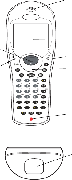
Parts of the PDT 7500
Scan Button LCD
Power Key
Scan LED
Front View
Communication LED
Battery Charge
LED Thumb Rest
Top View
Scan Window
PRELIMINARY
4
PDT 7500 Series
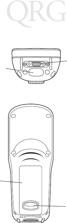
Parts of the PDT 7500 (continued)
Bottom View
Serial
Communications
Port
IrDA Port
Back View
Battery Latch
Li-Ion Battery
PRELIMINARY
5
Quick Reference
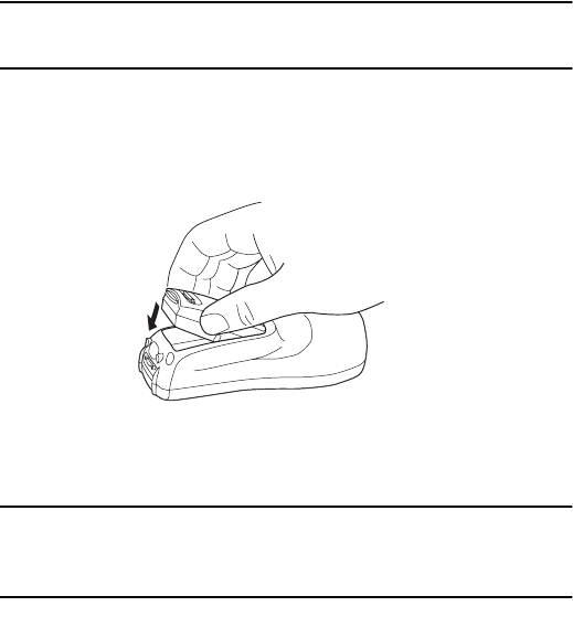
Installing New or Recharged Batteries
Caution: To ensure proper terminal operation, use ONLY the
Symbol Li-Ion battery in the PDT 7500.
To install a new or recharged Li-Ion battery:
1. Hook the base of the new battery in the top of the battery
compartment, then press the into place.
2. Slide the battery latch to secure the battery.
If the battery latch is not closed, do not operate the terminal,
otherwise data may be lost.
Caution: Do not expose the battery to temperatures in excess of
140°F (60°C). Do not disassemble, incinerate, or short
circuit the battery.
PRELIMINARY
6
PDT 7500 Series
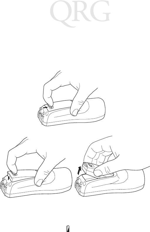
Removing the Battery from the Terminal
To remove the Li-Ion battery from the terminal:
1. Suspend the terminal’s power.
2. Slide the battery release switch towards the top of the terminal
until the lock releases.
3. Lift the battery up and out of the battery compartment.
Charging the Battery in the Terminal
To charge the terminal’s battery, place the PDT 7500 in the cradle
or connect the synchronization/charging cable.
The terminal’s charging LED turns yellow while charging, then
turns green when the battery is fully charged, which takes 2-3
hours. A flashing yellow LED indicates there may be a problem with
the battery.
PRELIMINARY

7
Quick Reference
For instructions on setting up the cradle, refer to the Quick
Reference Guide that shipped with your cradle or to the PDT 7500
Series Product Reference Guide (72-39225-xx for DOS terminals,
or 72-41235-xx for Windows CE Terminals).
Charging the Spare Battery
The cradle also has a spare battery charging slot. To charge the
spare Li-Ion battery in the CRD 7500 cradle, place the battery into
the charging slot in the cradle. Charging begins automatically and
the charge LED on the cradle turns yellow. The charge LED turns
green upon successful completion of the charge cycle, which takes
approximately 4 hours. If the LED does not light, no battery is
present. If the LED blinks yellow, the battery is faulty.
You may also charge the battery in the UBC 2000 Battery Charger.
See the Quick Reference Guide which came with the UBC 2000 for
more information.
LED Indication
For all charging methods, the terminal’s battery charging LED
indicates the battery charging status, as follows:
Battery Charge State Charge LED Indication
Battery absent/no charge power Off
Battery charging Yellow
Battery fully charged Green
Abnormal battery Flashing Yellow
PRELIMINARY

8
PDT 7500 Series
Operating the PDT 7500
Powering the Terminal On/Off
Note: Before the terminal can be powered on, it must be ini-
tialized and the battery must be fully charged. Refer to
the PDT 7500 Series Product Reference Guide for your
terminal for information on initializing the terminal.
To power on the terminal:
1. Make sure the terminal’s battery is fully charged.
2. Press the PWR key.
To suspend the terminal’s operation, press the PWR key.
Turning the Backlight On/Off
To turn the backlight on or off, press the blue FUNC key, then the
LAMP key.
Controlling the Screen Contrast
To lighten the screen contrast, press the blue FUNC key, then the
LIGHT key. To darken the screen contrast, press the FUNC key,
then the DARK Key.
Resetting the PDT 7500
If your PDT 7500 Series terminal stops responding to input from
buttons on the screen, you must reset it.
Performing a Warm Boot (DOS and Windows CE Terminals)
A warm boot restarts the terminal and saves all stored records and
entries.
Note: Files that remain open during a warm boot may not be
retained.
To perform a warm boot, press and hold down the PWR key for 6
seconds, then release.
PRELIMINARY
9
Quick Reference
Performing a Cold Boot (DOS and Windows CE Terminals)
A cold boot restarts the terminal. In the Windows CE environment,
the registry and objects stored are reset to original settings.
To perform a cold boot, press and hold the PWR key for 15 seconds,
then release. On the DOS terminal, this value can be reconfigured
in Setup (see the Product Reference Guide for more information).
Performing a Hard Reset (Windows CE Terminals Only)
A hard reset also restarts the PDT 7500 Series terminal, but erases
all stored records and entries. Therefore, never perform a hard reset
unless a warm/cold boot does not solve your problem.
Note: On the Windows CE terminal, you can restore any data
previously synchronized with your computer during the
next ActiveSync operation. See the Quick Reference
Guide which came with your cradle, or the PDT 7500
Product Reference Guide for Windows CE for more in-
formation.
To perform a hard reset:
1. Remove the battery for 20 minutes or longer.
2. Replace the battery in the terminal.
3. The calibration screen displays.
Note: With a hard reset, formats preferences and other settings
are restored to their original factory defaults.
Calibrating the Screen (Windows CE Terminals Only)
The first time you start your PDT 7500 terminal (and whenever the
terminal is cold-booted), the calibration screen displays. This
section describes how to calibrate your terminal so the cursor on the
touch screen aligns with the tip of your stylus.
Note: If your terminal came loaded with another software ap-
plication, the calibration screen may not display.
PRELIMINARY

10
PDT 7500 Series
To calibrate your PDT 7500 terminal:
1. If necessary, adjust the contrast on the PDT 7500 so the screen
is clear and readable. See “Controlling the Screen Contrast”
on page 8 for instructions.
2. As the screen instructs, carefully press and briefly hold the sty-
lus on the center of each target. Repeat as the target moves
around the screen.
3. Tap the screen when prompted to accept new calibration.
PRELIMINARY
11
Quick Reference
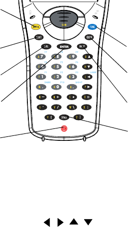
Using the PDT 7500 Keypad
The PDT 7500 uses an alphanumeric keypad that produces the 26-
character alphabet (A-Z), numbers (0-9), and assorted characters.
The keypad is color-coded to indicate which modifier key (ALPHA,
CTRL, FUNC, and SHIFT) to press to produce a particular
character or action.
• The default numeric keypad produces the numbers 0-9.
• Press ALPHA and the appropriate key to produce the alpha
characters A-Z.
• Press FUNC (blue) and the corresponding numeric key to pro-
duce the function keys F1-F10.
• Press the cursor keys ( , , , ) to move the cursor left,
right, up and down on the screen.
• Press BKSP to erase information entered on the display, one
character at a time.
• Press SPACE to enter a blank space.
• Press CLEAR to partially or completely escape from an appli-
cation level or screen. CLEAR also erases all entered data
from the screen.
Function key
Space key
Enter key
Alpha key
Backspace key
Shift key
Control key Clear key
Power key
PRELIMINARY

12
PDT 7500 Series
•Press ENTER after entering data or a command.
•Press CTRL to perform the control function. This key is un-
der application control.
•Press SHIFT and a key to produce various character keys; refer
to the PDT 7500 Series Product Reference Guide for your ter-
minal or your application guide for the keypad mapping.
Note: Key function can be changed by an application. Your
keypad may not function exactly as described above.
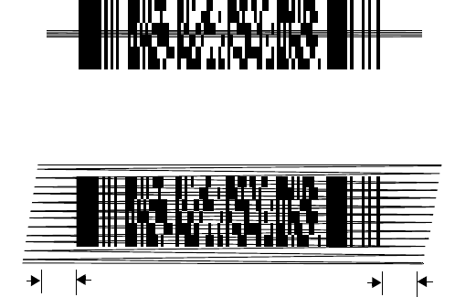
Using the Integrated Laser Scanner
To use the laser scanner:
1. Verify the system is on. The LED lights yellow if scanning is
enabled and the laser is on.
2. Aim the PDT 7500 scan window at the bar code and press the
scan button.
Do not hold the PDT 7500 at a right angle to the bar code.
You can tilt the 7500 up to 65° forward or backward and
achieve a successful decode.
3. Ensure that the scan beam crosses all bars and spaces on the
symbol, as shown below.
Hold the scanner farther away for larger symbols, and closer
for symbols with bars that are close together.
4. The LED turns from yellow to green for successful decodes.
The PDT 7500 may also beep on successful decode.
Right Wrong
PRELIMINARY
13
Quick Reference
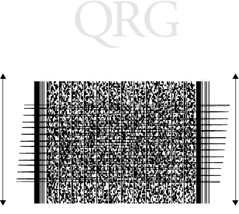
Scanning PDF417 Bar Codes
The PDF417 bar code symbol has multiple rows, but the raster
pattern also has multiple scanning rows. Two basic steps are
required as you scan:
1. Point the scanner at the bar code and press the scan button.
2. As the raster pattern spreads, keep the pattern in the same hor-
izontal plane as the bar code.
3. The terminal indicates a successful scan by changing the LED
from yellow to green, beeping one or more times, and/or dis-
playing the decoded bar code on the screen.
“Tall” PDF Bar Codes
If the PDF417 symbol is “tall,” the vertical scan pattern may not be
high enough to cover it.
In this case, try a slow “up and down” scanning motion. With the
raster pattern open, try to move the scanner slowly down toward
the bottom of the symbol, keeping the beam horizontal to the rows,
and then slowly back upward toward the top.
Slab Raster
3/4” 3/4”
PRELIMINARY
14
PDT 7500 Series
The scan beam does not have to be perfectly parallel with the top
and bottom of the symbol (up to a 4o tilt will work).
PRELIMINARY
15
Quick Reference
Host Communications
The PDT 7500 Series terminal can communicate with a host PC
either directly through its communications port using an RS-232
serial cable or the cradle, or wirelessly via the Spectrum24® wireless
LANs. For more information on setting up and performing wireless
communications with your PDT 7540 terminal, refer to the PDT
7500 Series Product Reference Guide.
Using the RS-232 Serial Cable
To connect the RS-232 serial cable for host communication:
1. Connect the RS-232 serial communication cable’s connector
to the adapter cable’s connector.
2. Plug the adapter cable’s subminiature connector into the serial
communication port on the bottom of the terminal.
3. Plug the other end of the RS-232 serial communication cable
into the host PC.
4. Begin host communication as specified by your application.
Using the Cradle
To communicate through the cradle:
1. Make sure all connections between the cradle and the host
computer are secure. See the Quick Reference Guide that
shipped with your cradle for instructions on setting up the cra-
dle.
2. Power on the host computer, the cradle, and the terminal.
3. Insert the terminal into the cradle.
4. Begin host communications as specified by your application.
PRELIMINARY

16
PDT 7500 Series
Communicating with Printers
The PDT 7500 communicates with IrDA-compliant peripherals
through the IrDA interface in the base of the terminal. To print,
point the PDT 7500’s IrDA port at the IrDA port on the IrDA-
compliant printer from a maximum distance of 39 inches (1 meter)
and run the application’s print function. Printer communication can
also be established through an RS-232 cable connected directly to
the printer.
Using the Touch Screen
Some PDT 7500 terminals are equipped with a Touch Screen, which
has software that allows the stylus to function as a mouse. An
optional stylus is available from Symbol for use with the terminal.
Further use of the stylus function is application-dependent. Refer to
application documentation for more information.
Troubleshooting
Problem Cause Solution
PDT 7500 does
not power on. Li-Ion battery
not charged. Charge or replace the Li-Ion
battery in the PDT 7500.
System crash. Hold PWR key for 15 seconds.
DOS terminal users may change
this value in Setup.
Rechargeable
Li-Ion battery
did not charge.
Battery failed. Replace battery.
PDT 7500 re-
moved from cra-
dle while battery
was charging.
Insert PDT 7500 in cradle and
begin charging. The Li-Ion bat-
tery requires 2-3 hours to re-
charge fully.
PRELIMINARY

17
Quick Reference
Cannot see
characters on
display.
PDT 7500 not
powered on. Press the PWR key.
Contrast not ad-
justed properly. Press the blue FUNC key and
then the Dark or Light keys to
adjust contrast.
Scanner does
not power on
when the scan
button is
pressed.
Scanner is not
enabled. See your System Administrator.
Scanner does
not decode a
bar code.
Bar code is un-
readable. Verify that the bar code is not
defective, i.e., smudged or bro-
ken.
Scan window is
dirty. Clean scan window with a lens
tissue. Tissues for eyeglasses
work well. Do not use tissues
coated with lotion.
Scan code not
enabled. See your System Administrator.
Problem Cause Solution
PRELIMINARY

18
PDT 7500 Series
Fail to commu-
nicate with
IrDA printer.
Distance from
printer is more
than 1 meter
(3.28 feet).
Bring the terminal closer to the
printer and attempt communi-
cations again.
Obstruction in-
terfered with
communication.
Check the path to ensure no ob-
jects were in the way.
Application is
not enabled to
run IrDA print-
ing.
Printer support must be includ-
ed with the application to run
IrDA printing on the terminal.
See your System Administrator.
Problem Cause Solution
PRELIMINARY

19
Quick Reference
Pin-Outs
Regulatory Information
Radio Frequency Interference Requirements
This device has been tested and found to comply with the limits for a Class A digital
device pursuant to Part 15 of the Federal Communications Commissions Rules and
Regulation. These limits are designed to provide reasonable protection against harmful
interference when the equipment is operated in a commercial environment. This
equipment generates, uses, and can radiate radio frequency energy and, if not installed
and used in accordance with the instruction manual, may cause harmful interference to
radio communications. Operation of this equipment in a residential area is likely to
cause harmful interference in which case the user will be required to correct the
interference at his own expense.
Pin Description
1GND
2DSR
3RXD
4CTS
5DCD
6GND
7 PWROUT (+5V)
8 PWRIN(+15V)
9DTR
10 Ring
11 TXD
12 RTS
13 Reserved
14 GND
15 PWRIN(+15V)
PRELIMINARY

20
PDT 7500 Series
However, there is no guarantee that interference will not occur in a particular
installation. If the equipment does cause harmful interference to radio or television
reception, which can be determined by turning the equipment off and on, the user is
encouraged to try to correct the interference by one or more of the following measures:
• Re-orient or relocate the receiving antenna.
• Increase the separation between the equipment and receiver.
• Connect the equipment into an outlet on a circuit different from that which the
receiver is connected.
• Consult the dealer or an experienced radio/TV technician for help.
This device complies with FCC Part 15. Operation is subject to the following two
conditions: (1) this device may not cause harmful interference and (2) this device must
accept any interference received, including interference that may cause undesired
operation.
Important Note: To comply with FCC and Industry Canada RF exposure requirements,
this hand-held device is approved for operation in a user's hand when there is 20 cm or
more between the antenna and the user's body.
Radio Frequency Interference Requirements - Canada
This device complies with RSS 210 of Industry & Science Canada. Operation is subject
to the following two conditions: (1) this device may not cause harmful interference and
(2) this device must accept any interference received, including interference that may
cause undesired operation.
This Class B digital apparatus complies with Industry Canada Standard ICES-003.
Cet appareil numérique de la classe B est conform à la norme NMB-003 d’Industrie
Canada.
CE Marking and European Union Compliance
Products intended for sale within the European Union are marked with the
CE Mark which indicates compliance to applicable Directives and
European Normes (EN), as follows. Amendments to these Directives or
ENs are included:
Applicable Directives
• Electromagnetic Compatibility Directive 89/336/EEC
• Low Voltage Directive 73/23/EEC
PRELIMINARY
21
Quick Reference
Applicable Standards
• EN 55 022 - Limits and Methods of Measurement of Radio Interference Charac-
teristics of Information technology Equipment
• EN 55024:1998; Information technology equipment-Immunity characteristics-
Limits and methods of measurement.
• EN 50 082-1:1997 - Electromagnetic Compatibility - Generic Immunity Stan-
dard, Part 1: Residential, commercial, Light Industry
• IEC 1000-4-2(1995-01) - Electromagnetic compatibility (EMC) - Part 4:Testing
and measurement techniques - Section 2: Electrostatic discharge immunity test.
• IEC 1000-4-3(1995-03) - Electromagnetic compatibility (EMC) - Part 4:Testing
and measurement techniques - Section 3: Radiated, radio-frequency, electromag-
netic field immunity test.
• IEC 1000-4-4(1995-01) - Electromagnetic compatibility (EMC) - Part 4:Testing and
measurement techniques - Section 4: Electrical fast transient/burst immunity test.
• EN 60 950 + Amd 1 + Amd 2 - Safety of Information Technology Equipment
Including Electrical Business Equipment
• EN 60 825-1 (EN 60 825) - Safety of Devices Containing Lasers.
Laser Devices
Symbol products using lasers comply with US 21CFR1040.10, Subchapter J and
IEC825/EN 60 825 (or IEC825-1/EN 60 825-1, depending on the date of
manufacture). The laser classification is marked on one of the labels on the product.
Class 1 Laser devices are not considered to be hazardous when used for their intended
purpose. The following statement is required to comply with US and international
regulations:
Caution: Use of controls, adjustments or performance of procedures other than those
specified herein may result in hazardous laser light exposure.
Class 2 laser scanners use a low power, visible light diode. As with any very bright light
source, such as the sun, the user should avoid staring directly into the light beam.
Momentary exposure to a Class 2 laser is not known to be harmful.
RF Devices
Symbol’s RF products are designed to be compliant with the rules and regulations in
the locations into which they are sold and will be labeled as required. The majority of
Symbol’s RF devices are type approved and do not require the user to obtain license or
authorization before using the equipment. Any changes or modifications to Symbol
Technologies equipment not expressly approved by Symbol Technologies could void
the user’s authority to operate the equipment.
PRELIMINARY
22
PDT 7500 Series
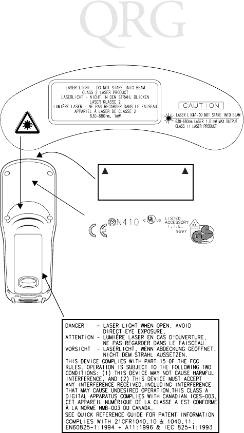
Scanner Labeling
AVOID EXPOSURE - LASER LIGHT IS
EMITTED FROM THIS APERTURE
ÉVITER TOUTE EXPOSITION -
LUMIÈRE LASER ÉMIS PAR CETTE OUVERTURE
This label is located inside the battery compartment.
PRELIMINARY
23
Quick Reference
In accordance with Clause 5, IEC 0825 and EN60825, the following information is
provided to the user:
ENGLISH HEBREW
CLASS 1 CLASS 1 LASER PRODUCT
CLASS 2 LASER LIGHT
DO NOT STARE INTO BEAM
CLASS 2 LASER PRODUCT
DANISH
KLASSE 1 KLASSE 1 LASERPRODUKT ITALIAN
KLASSE 2 LASERLYF CLASSE 1 PRODOTTO AL LASER DI CLASSE 1
SE IKKE IND I STRÅLEN CLASSE 2 LUCE LASER
KLASSE 2 LASERPRODUKT NON FISSARE IL RAGGIOPRODOTTO
AL LASER DI CLASSE 2
DUTCH
KLASSE 1 KLASSE-1 LASERPRODUKT NORWEGIAN
KLASSE 2 LASERLICHT KLASSE 1 LASERPRODUKT, KLASSE 1
NIET IN STRAAL STAREN KLASSE 2 LASERLYS IKKE STIRR INN I LYSSTRÅLEN
KLASSE-2 LASERPRODUKT LASERPRODUKT, KLASSE 2
FINNISH PORTUGUESE
LUOKKA 1 LUOKKA 1 LASERTUOTE CLASSE 1 PRODUTO LASER DA CLASSE 1
LUOKKA 2 LASERVALO
ÄLÄ TUIJOTA SÄDETTÄ CLASSE 2 LUZ DE LASER NÃO FIXAR O RAIO LUMINOSO
LUOKKA 2 LASERTUOTE PRODUTO LASER DA CLASSE 2
FRENCH SPANISH
CLASSE 1 PRODUIT LASER DE CLASSE 1 CLASE 1 PRODUCTO LASER DE LA CLASE 1
CLASSE 2 LUMIERE LASER CLASE 2 LUZ LASER
NE PAS REGARDER LE RAYON FIXEMENT NO MIRE FIJAMENTE EL HAZ
PRODUIT LASER DE CLASSE 2 PRODUCTO LASER DE LA CLASE 2
GERMAN SWEDISH
KLASSE 1 LASERPRODUKT DER KLASSE 1 KLASS 1 LASERPRODUKT KLASS 1
KLASSE 2 LASERSTRAHLEN KLASS 2 LASERLJUS STIRRA INTE MOT STRÅLEN
NICHT DIREKT IN DEN LASERSTRAHL SCHAUEN LASERPRODUKT KLASS 2
LASERPRODUKT DER KLASSE 2
PRELIMINARY

24
PDT 7500 Series
Service Information
Before you use the unit, it must be configured to operate in your facility’s network and
run your applications.
If you have a problem running your unit or using your equipment, contact your
facility’s Technical or Systems Support. If there is a problem with the equipment, they
will contact the Symbol Support Center.
Warranty
Symbol Technologies, Inc. (“Symbol”) manufactures its hardware products in
accordance with industry-standard practices. Symbol warrants that for a period of
twelve (12) months from date of shipment, products will be free from defects in
materials and workmanship.
This warranty is provided to the original owner only and is not transferable to any third
party. It shall not apply to any product (i) which has been repaired or altered unless
done or approved by Symbol, (ii) which has not been maintained in accordance with
any operating or handling instructions supplied by Symbol, (iii) which has been
subjected to unusual physical or electrical stress, misuse, abuse, power shortage,
negligence or accident or (iv) which has been used other than in accordance with the
product operating and handling instructions. Preventive maintenance is the
responsibility of customer and is not covered under this warranty.
Wear items and accessories having a Symbol serial number, will carry a 90-day limited
warranty. Non-serialized items will carry a 30-day limited warranty.
United States 1-800-653-5350 Canada 905-629-7226
United Kingdom 0800 328 2424 Asia/Pacific 337-6588
Australia 1-800-672-906 Austria 1-505-5794
Denmark 7020-1718 Finland 9 5407 580
France 01-40-96-52-21 Germany 6074-49020
Italy 2-484441 Mexico 5-520-1835
Netherlands 315-271700 Norway 66810600
South Africa 11-4405668 Spain 9-1-320-39-09
Sweden 84452900
Latin America Sales Support 1-800-347-0178 Inside US
+1-561-483-1275 Outside US
Europe/Mid-East Distributor Operations Contact local distributor or call
+44 208 945 7360
PRELIMINARY

25
Quick Reference
Warranty Coverage and Procedure
During the warranty period, Symbol will repair or replace defective products returned
to Symbol’s manufacturing plant in the US. For warranty service in North America, call
the Symbol Support Center at 1-800-653-5350. International customers should contact
the local Symbol office or support center. If warranty service is required, Symbol will
issue a Return Material Authorization Number. Products must be shipped in the
original or comparable packaging, shipping and insurance charges prepaid. Symbol
will ship the repaired or replacement product freight and insurance prepaid in North
America. Shipments from the US or other locations will be made F.O.B. Symbol’s
manufacturing plant.
Symbol will use new or refurbished parts at its discretion and will own all parts
removed from repaired products. Customer will pay for the replacement product in
case it does not return the replaced product to Symbol within 3 days of receipt of the
replacement product. The process for return and customer’s charges will be in
accordance with Symbol’s Exchange Policy in effect at the time of the exchange.
Customer accepts full responsibility for its software and data including the appropriate
backup thereof.
Repair or replacement of a product during warranty will not extend the original
warranty term.
Symbol’s Customer Service organization offers an array of service plans, such as on-site,
depot, or phone support, that can be implemented to meet customer’s special
operational requirements and are available at a substantial discount during warranty
period.
General
Except for the warranties stated above, Symbol disclaims all warranties, express or
implied, on products furnished hereunder, including without limitation implied
warranties of merchantability and fitness for a particular purpose. The stated express
warranties are in lieu of all obligations or liabilities on part of Symbol for damages,
including without limitation, special, indirect, or consequential damages arising out of
or in connection with the use or performance of the product.
Seller’s liability for damages to buyer or others resulting from the use of any product,
shall in no way exceed the purchase price of said product, except in instances of injury
to persons or property.
Some states (or jurisdictions) do not allow the exclusion or limitation of incidental or
consequential damages, so the proceeding exclusion or limitation may not apply to you.
This product is marked with in accordance with the Class II
product requirements specified in the R&TTE Directive, 1999/5/EC.
The equipment is intended for use throughout the European Community, but it's
authorization for use in France is restricted as follows:
• PAN European Frequency Range: 2.402 - 2.480 GHz
• Restricted Frequency Range for use in France: 2.448 - 2.480 GHz
0168
PRELIMINARY

72-38888-02
Revision A — April 2000
Symbol Technologies, Inc. One Symbol Plaza Holtsville, NY 11742-1300
PRELIMINARY