Symbol Technologies RA1202 UHF Narrowband Radio Module User Manual Omnii Hand Held Computer
Symbol Technologies Inc UHF Narrowband Radio Module Omnii Hand Held Computer
Contents
- 1. User Manual
- 2. User Manual 1of2
- 3. User Manual 2of2
- 4. Regulatory Warranty Guide
User Manual 2of2
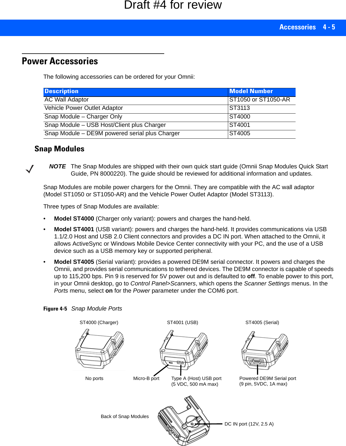
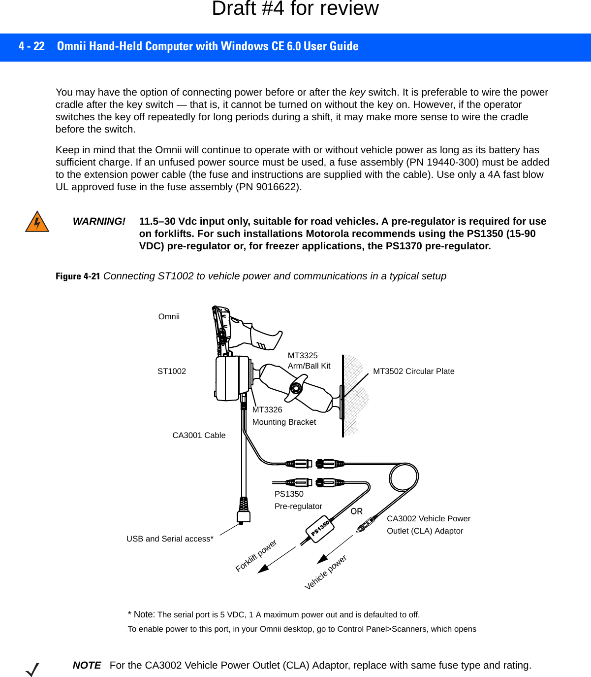
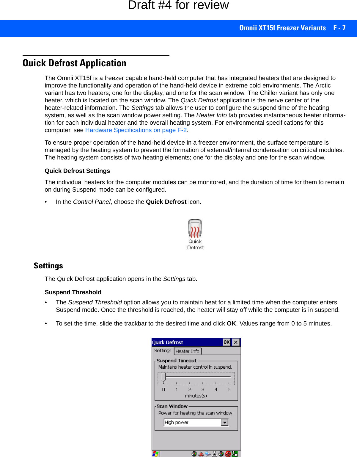
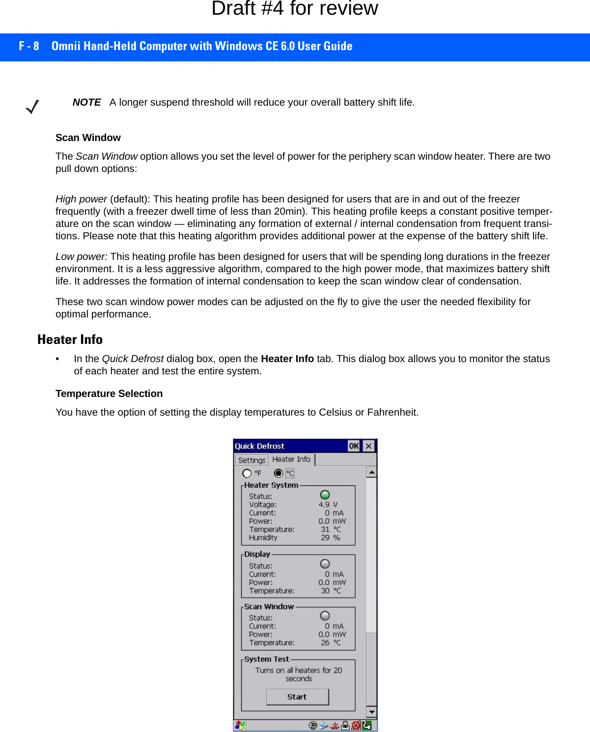
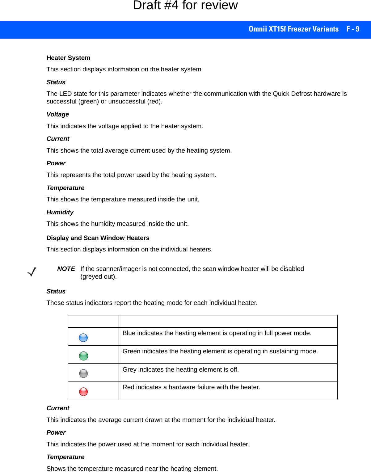
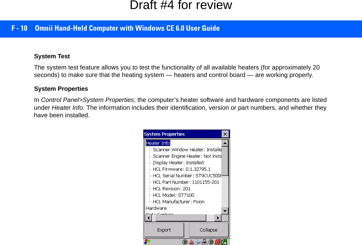
![APPENDIX B IMAGER & CAMERA SETTINGSBImager & Camera SettingsIntroductionThe Imagers applet is used to create, modify, delete, and activate imager settings. The principal uses of the application are to decode barcodes and to capture images. This imager services application is used for cameras and imagers to configure linear (1D), stacked linear, matrix (true 2D) and postal barcodes. ADemonstration Application is provided to demonstrate how the imager works. Refer to Demo on page 2-21 for details.Required AppletsIn order to configure imaging, the Manage Triggers applet must be present in the Control Panel, along with the Imagers applet. Presets There are two methods that can be used to configure an imager using the Imagers applet:• Use a predefined preset.• Create a custom preset based on a predefined preset.NOTE The Imagers icon is only displayed when the appropriate imager is installed in your Omnii. If there is an imager installed but this icon is not present, additional software (ICS) may need to be installed.To enable a newly-installed imager, press and hold down the [FN] key and the [Enter/Power] key simultaneously for a minimum of three seconds. IMPORTANT It is strongly recommended that a predefined preset is used whenever possible. Each predefined preset contains a coherent group of settings that are known to work together in the intended environment. In almost all situations, at least one of the predefined presets results in a satisfactory outcome.Draft #4 for review](https://usermanual.wiki/Symbol-Technologies/RA1202.User-Manual-2of2/User-Guide-2406596-Page-27.png)
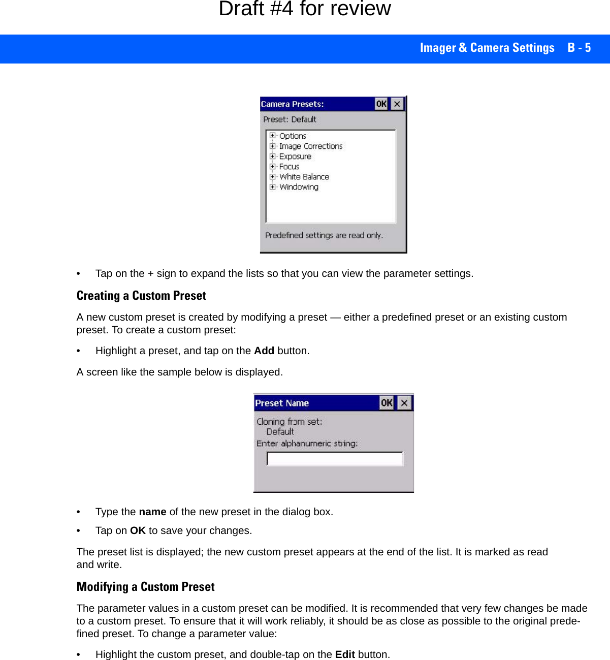
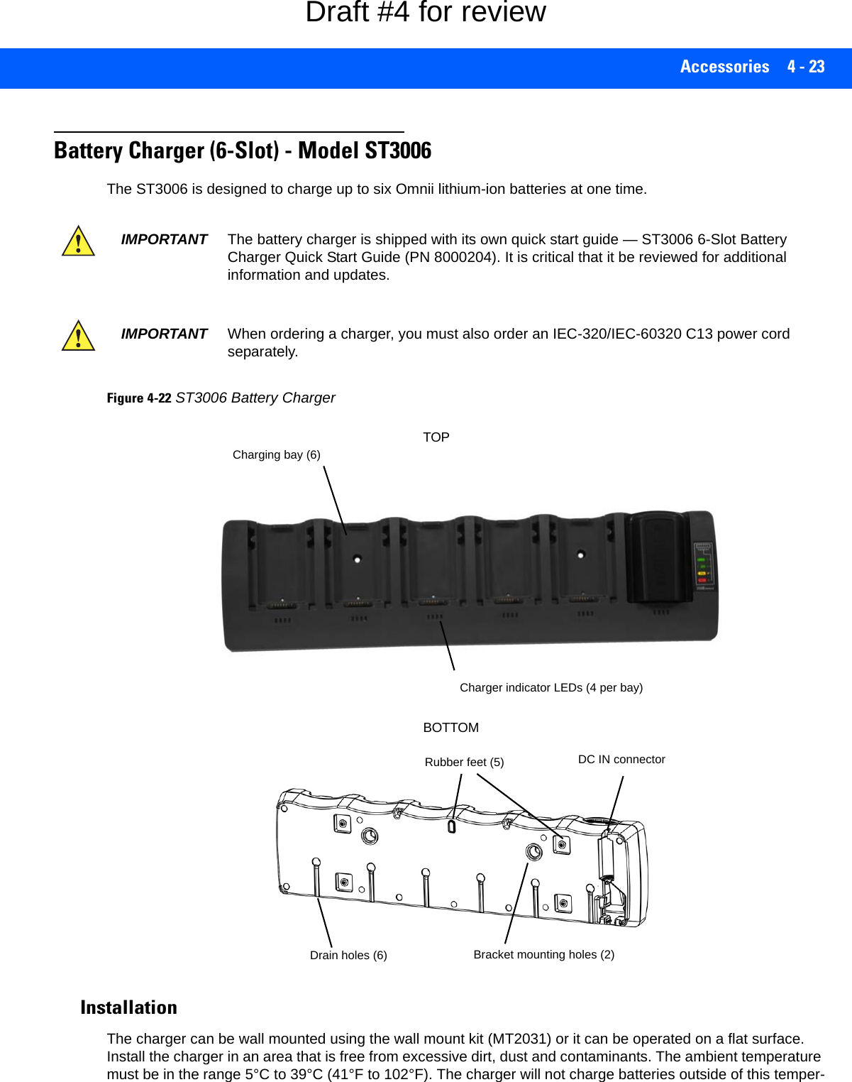
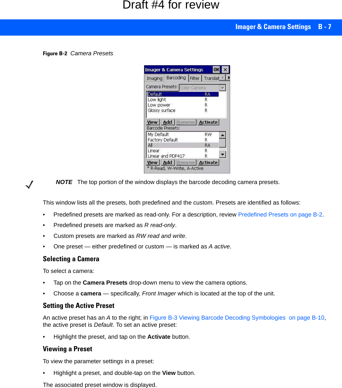
![B - 6 Omnii Hand-Held Computer with Windows CE 6.0 User Guide• Tap on the + symbols to expand the lists so that you can view the parameter settings.• Scroll through the parameter list until you reach the parameter that you want to change.• For a parameter that can take a range of values:- Highlight the parameter, and then press the [SPACE] key or double-click on the parameter.- An associated dialog box containing the valid range of values for the parameter and the current setting like the sample screen following is displayed.- Type a value in the field provided.• For a parameter that toggles between two values such as on or off and enabled or disabled:- Highlight the parameter and then press the [SPACE] key, or double-click on the parameter. Either method toggles between the two available values.• When you’ve completed your edits, tap on OK.The parameter list is displayed; the new value for the changed parameter is shown.•Tap on OK to exit to the preset list and save the changes.Removing a Custom Preset• Highlight the custom preset you want to delete, and tap on the Remove button.A window is displayed warning you that you are about to remove a preset.•Tap on Yes to remove the preset or No to cancel the operation.Configuring the Barcode Decoding Camera Presets (Barcoding Menu)To configure the barcode decoding camera presets:•Tap on Start>Settings>Control Panel>Imagers.• Tap on the Barcoding tab.Draft #4 for review](https://usermanual.wiki/Symbol-Technologies/RA1202.User-Manual-2of2/User-Guide-2406596-Page-32.png)
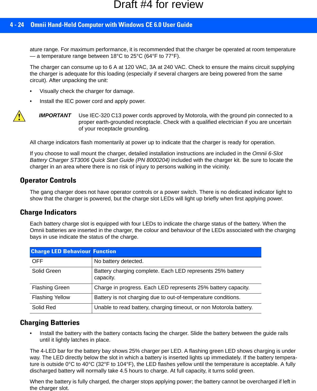
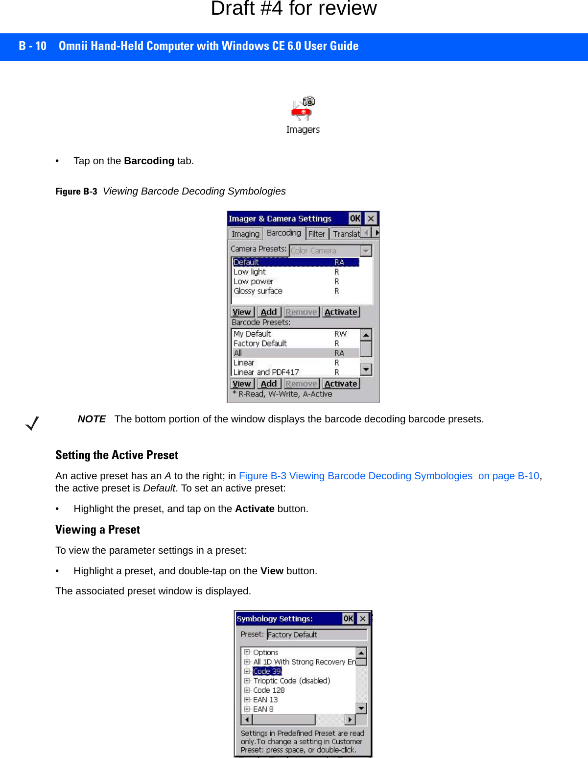
![Imager & Camera Settings B - 9• Tap on the + symbols to expand the lists and view the parameter settings.• Scroll through the parameter list until you reach the parameter that you want to change.• For a parameter that can take a range of values:- Highlight the parameter, and then press the [SPACE] key or double-click the parameter.- An associated dialog box containing the valid range of values for the parameter and the current setting like the sample screen following is displayed.- Type a value in the field provided.• For a parameter that toggles between two values such as on or off and enabled or disabled:- Highlight the parameter and then press the [SPACE] key, or double-click on the parameter. Either method toggles between the two available values.• When you’ve completed your edits, tap on OK.The parameter list is displayed; the new value for the changed parameter is shown.•Tap on OK to exit to the preset list and save the changes.Removing a Custom Preset• Highlight the custom preset you want to delete, and tap on the Remove button.A window is displayed warning you that you are about to remove a preset.•Tap on Yes to remove the preset or No to cancel the operation.Configuring the Barcode Decoding Symbologies (Barcoding Menu)To configure the barcode decoding camera presets:•Tap on Start>Settings>Control Panel>Imagers.Draft #4 for review](https://usermanual.wiki/Symbol-Technologies/RA1202.User-Manual-2of2/User-Guide-2406596-Page-35.png)
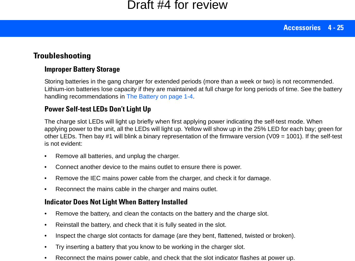
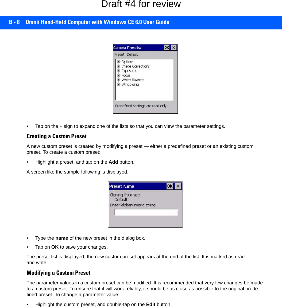
![Imager & Camera Settings B - 11• Tap on the + sign to expand one of the lists so that you can view the parameter settings.Creating a Custom PresetA new custom preset is created by modifying a preset — either a predefined preset or an existing custom preset. To create a custom preset:• Highlight a preset, and tap on the Add button.A screen like the sample following is displayed.• Type the name of the new preset in the dialog box.•Tap on OK to save your changes.The preset list is displayed; the new custom preset appears at the end of the list. It is marked as read and write.Modifying a Custom PresetThe parameter values in a custom preset can be modified. It is recommended that very few changes be made to a custom preset. To ensure that it will work reliably, it should be as close as possible to the original prede-fined preset. To change a parameter value:• Highlight the custom preset, and double-tap on the Edit button.• Tap on the + symbols to expand the lists and view the parameter settings.• Scroll through the parameter list until you reach the parameter that you want to change.• For a parameter that can take a range of values:- Highlight the parameter, and then press the [SPACE] key or double-click the parameter.- An associated dialog box containing the valid range of values for the parameter and the current setting like the sample screen following is displayed.Draft #4 for review](https://usermanual.wiki/Symbol-Technologies/RA1202.User-Manual-2of2/User-Guide-2406596-Page-37.png)
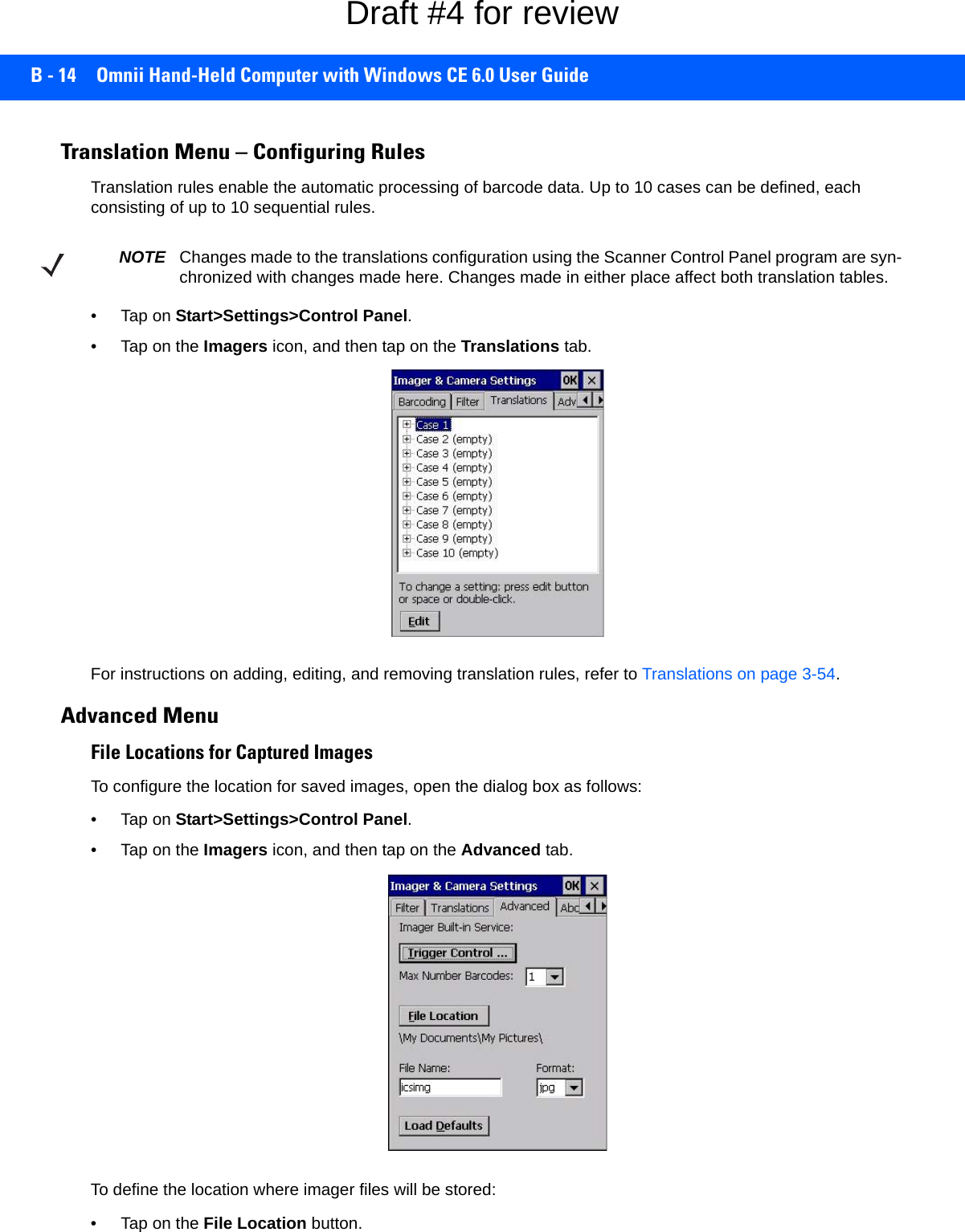
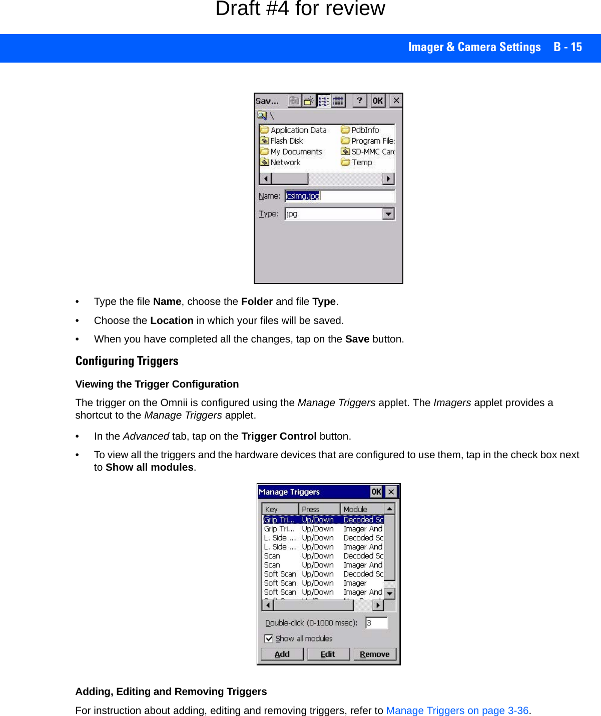
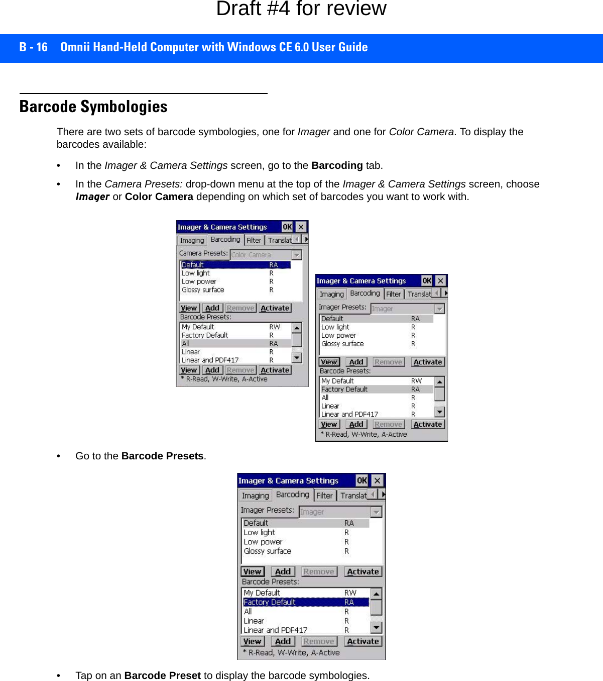
![B - 12 Omnii Hand-Held Computer with Windows CE 6.0 User Guide- Type a value in the field provided.• For a parameter that toggles between two values such as on or off and enabled or disabled:- Highlight the parameter and then press the [SPACE] key, or double-click on the parameter. Either method toggles between the two available values.• When you’ve completed your edits, tap on OK.The parameter list is displayed; the new value for the changed parameter is shown.•Tap on OK to exit to the preset list and save the changes.Removing a Custom Preset• Highlight the custom preset you want to delete, and tap on the Remove button.A window is displayed warning you that you are about to remove a preset.•Tap on Yes to remove the preset or No to cancel the operation.Barcoding Menu – Configuring SymbologiesTo view the Symbology Settings options:• Tap on the Barcoding tab, highlight All and then double-tap the View button.To edit a default preset, you must first activate it:•Tap on My Default, and tap on the Activate button – an A appears to the right of My Default.Once the preset is activated, you can enable or disable the barcodes the imager will read.• Highlight My Default in the Barcoding tab.• Double-tap on the Edit button.None of the other barcode decoding predefined presets are changed.Symbology SettingsFilter Menu – Manipulating Barcode DataTo configure rules for manipulating barcode data:•Tap on Start>Settings>Control Panel. • Tap on the Imagers icon, and then tap on the Filter tab.NOTE For descriptions of the barcode symbologies, review Barcode Symbologies on page B-16.Draft #4 for review](https://usermanual.wiki/Symbol-Technologies/RA1202.User-Manual-2of2/User-Guide-2406596-Page-38.png)
![Imager & Camera Settings B - 13Modifying a Barcode SettingThe rules for manipulating data from selected barcode symbologies can be modified. To change the settings for a symbology:• Tap on the + symbols to expand the lists and view the parameter settings.• Scroll through the parameter list until you reach the parameter that you want to change.• For a parameter that can take a range of values:- Highlight the parameter, and then press the [SPACE] key or double-click the parameter.- An associated dialog box containing the valid range of values for the parameter and the current setting like the sample screen following is displayed.- Type a value in the field provided.• For a parameter that takes a single character:- Highlight the parameter and then press the [SPACE] key, or double-click the parameter. The following screen is displayed:• When you’ve completed your edits, tap on OK.Draft #4 for review](https://usermanual.wiki/Symbol-Technologies/RA1202.User-Manual-2of2/User-Guide-2406596-Page-39.png)
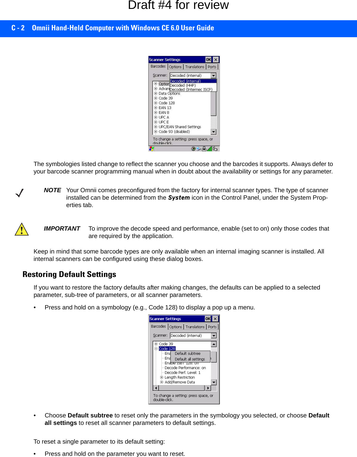
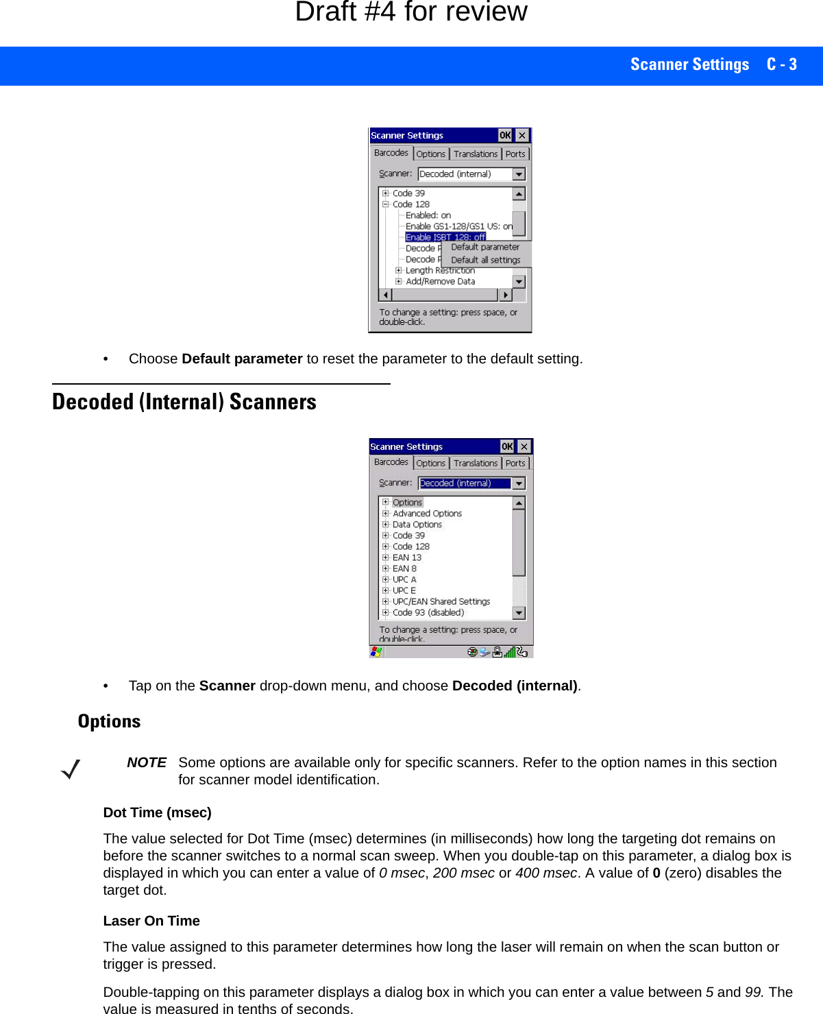
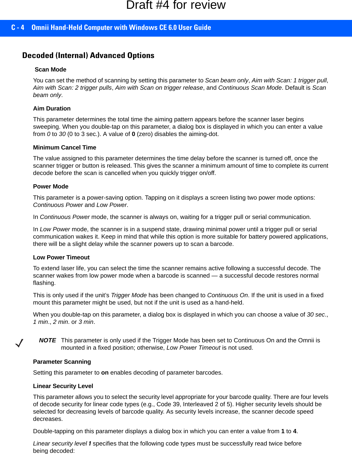
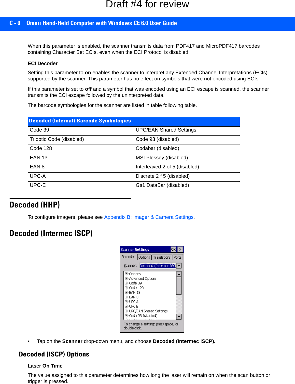
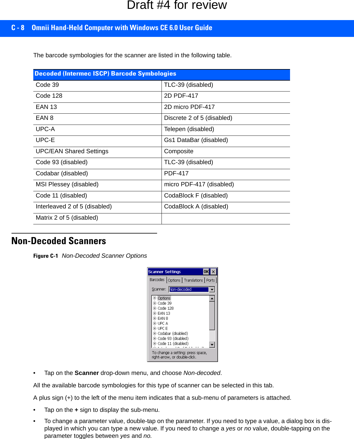
![APPENDIX C SCANNER SETTINGSCScanner SettingsBarcode SettingsThe Scanners icon in the Control Panel provides dialog boxes in which you can tailor barcode scanner config-urations and choose the barcodes your scanner will recognize.The parameters are preset with the default settings of the decoded scanner installed in the unit. For a listing of available scanners and their specifications, please refer to Appendix E: Omnii Specifications. Scanner OptionsThe drop-down menu to the right of the Scanner option allows you to choose configurations for one of the following scanner types, depending on what is installed in/on your hand-held: Decoded (internal), Decoded (HHP), Decoded (Intermec ISCP, and Non-decoded Scanners.IMPORTANT To enable a newly-installed scanner, press and hold down the [FN] key and the [Power] key simultaneously for a minimum of three seconds. For information on configuring the Options, Translations, and Ports settings, see Scan-ners on page 3-50.Draft #4 for review](https://usermanual.wiki/Symbol-Technologies/RA1202.User-Manual-2of2/User-Guide-2406596-Page-47.png)
![Scanner Settings C - 5Linear security level 2 specifies that all types of codes must be successfully read twice before being decoded.Linear security level 3 specifies that code types other than the following must be successfully read twice before being decoded. The following codes must be read three times:Linear security level 4 requires that all code types be successfully read three times before being decoded.Bi-Direction RedundancyWhen this parameter is enabled, a barcode must be successfully scanned in both directions (forward and reverse) before being decoded.Decoded (Internal) Data OptionsTransmit Code ID CharA code ID character identifies the scanned barcode type. In addition to any single character prefix already selected, the code ID character is inserted between the prefix and the decoded symbol.When you double-tap on this parameter, a dialog box is displayed in which you can choose a transmit code: None, AIM or Symbol.Scan Data FormatThis parameter allows you to change the scan data transmission format.Double-tapping on Scan Data Format displays the following options from which you can choose a data format: data (as-is), data [S1], data [S2], data [S1][S2], [P] data, [P] data [S1], [P] data [S2] and [P] data [S1][S2].Prefix [P], Suffix [S1] and Suffix [S2]A prefix and/or one or two suffixes may be appended to scan data for use in data editing. When you double-tap on these parameters, dialog boxes are displayed in which you can enter a value from 0 to 255.Delete Char Set ECIsSetting this parameter to on enables the scanner to delete any escape sequences representing Character Set ECIs (Extended Channel Interpretations [also known as GLIs]) from its buffer before transmission. Code Type LengthCodabar AllMSI Plessey 4 or lessD 5 of 5 8 or lessI 2 of 5 8 or lessCode Type LengthMSI Plessey 4 or lessD 2 of 5 8 or lessI 2 of 5 8 or lessNOTE This parameter is only valid if a “Linear Security Level” is enabled.Draft #4 for review](https://usermanual.wiki/Symbol-Technologies/RA1202.User-Manual-2of2/User-Guide-2406596-Page-51.png)
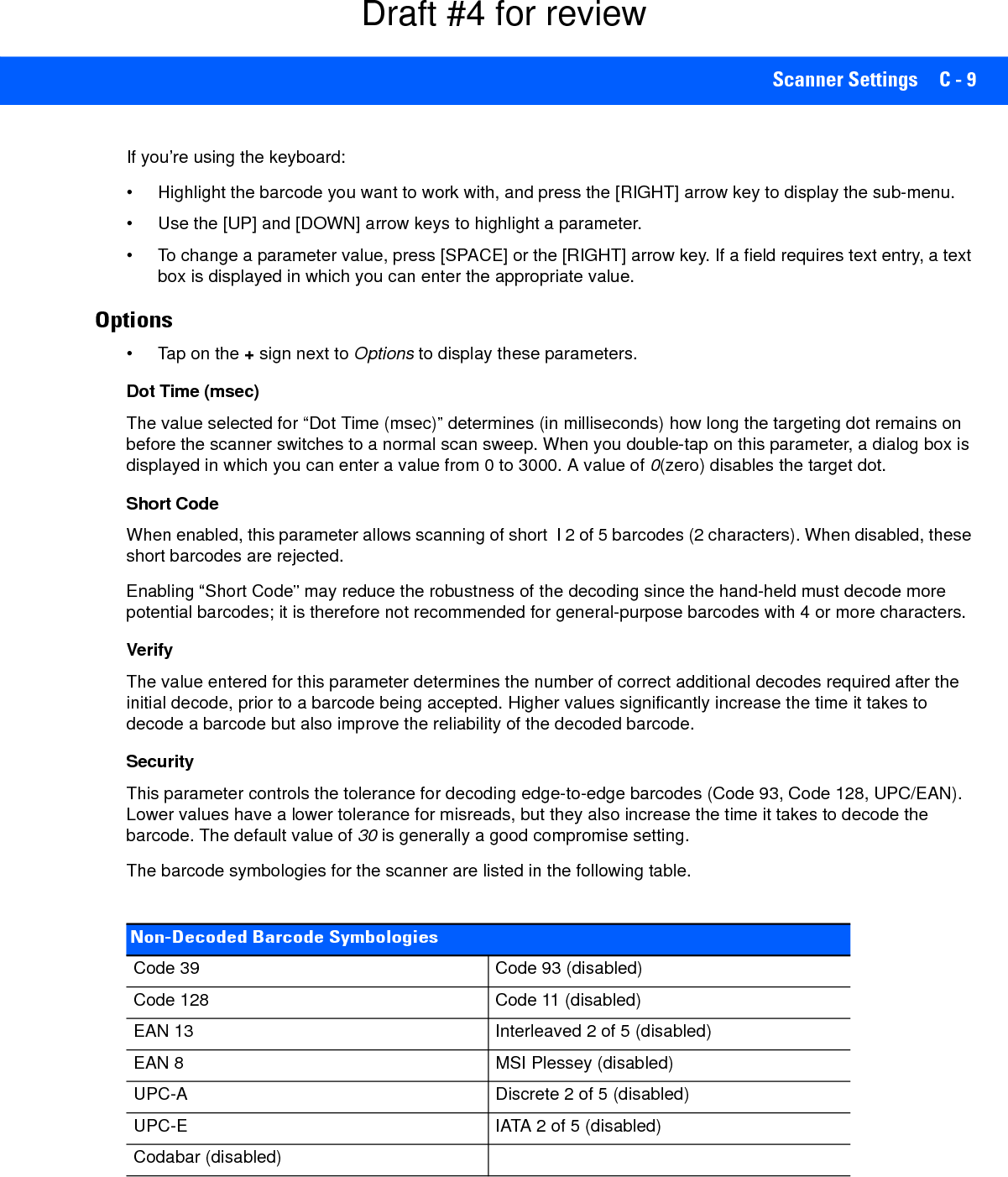
![Scanner Settings C - 9If you’re using the keyboard:• Highlight the barcode you want to work with, and press the [RIGHT] arrow key to display the sub-menu.• Use the [UP] and [DOWN] arrow keys to highlight a parameter. • To change a parameter value, press [SPACE] or the [RIGHT] arrow key. If a field requires text entry, a text box is displayed in which you can enter the appropriate value.Options• Tap on the + sign next to Options to display these parameters.Dot Time (msec)The value selected for “Dot Time (msec)” determines (in milliseconds) how long the targeting dot remains on before the scanner switches to a normal scan sweep. When you double-tap on this parameter, a dialog box is displayed in which you can enter a value from 0 to 3000. A value of 0(zero) disables the target dot.Short CodeWhen enabled, this parameter allows scanning of short I 2 of 5 barcodes (2 characters). When disabled, these short barcodes are rejected.Enabling “Short Code” may reduce the robustness of the decoding since the hand-held must decode more potential barcodes; it is therefore not recommended for general-purpose barcodes with 4 or more characters. VerifyThe value entered for this parameter determines the number of correct additional decodes required after the initial decode, prior to a barcode being accepted. Higher values significantly increase the time it takes to decode a barcode but also improve the reliability of the decoded barcode.SecurityThis parameter controls the tolerance for decoding edge-to-edge barcodes (Code 93, Code 128, UPC/EAN). Lower values have a lower tolerance for misreads, but they also increase the time it takes to decode the barcode. The default value of 30 is generally a good compromise setting.The barcode symbologies for the scanner are listed in the following table.Non-Decoded Barcode SymbologiesCode 39 Code 93 (disabled)Code 128 Code 11 (disabled)EAN 13 Interleaved 2 of 5 (disabled)EAN 8 MSI Plessey (disabled)UPC-A Discrete 2 of 5 (disabled)UPC-E IATA 2 of 5 (disabled)Codabar (disabled)Draft #4 for review](https://usermanual.wiki/Symbol-Technologies/RA1202.User-Manual-2of2/User-Guide-2406596-Page-55.png)


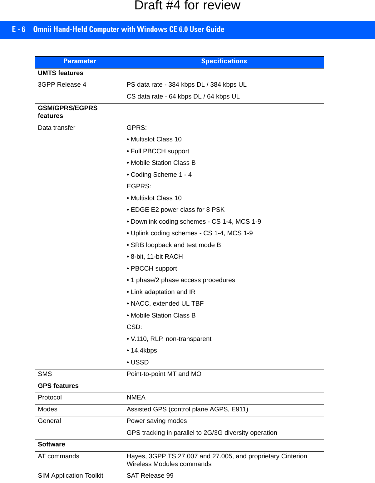
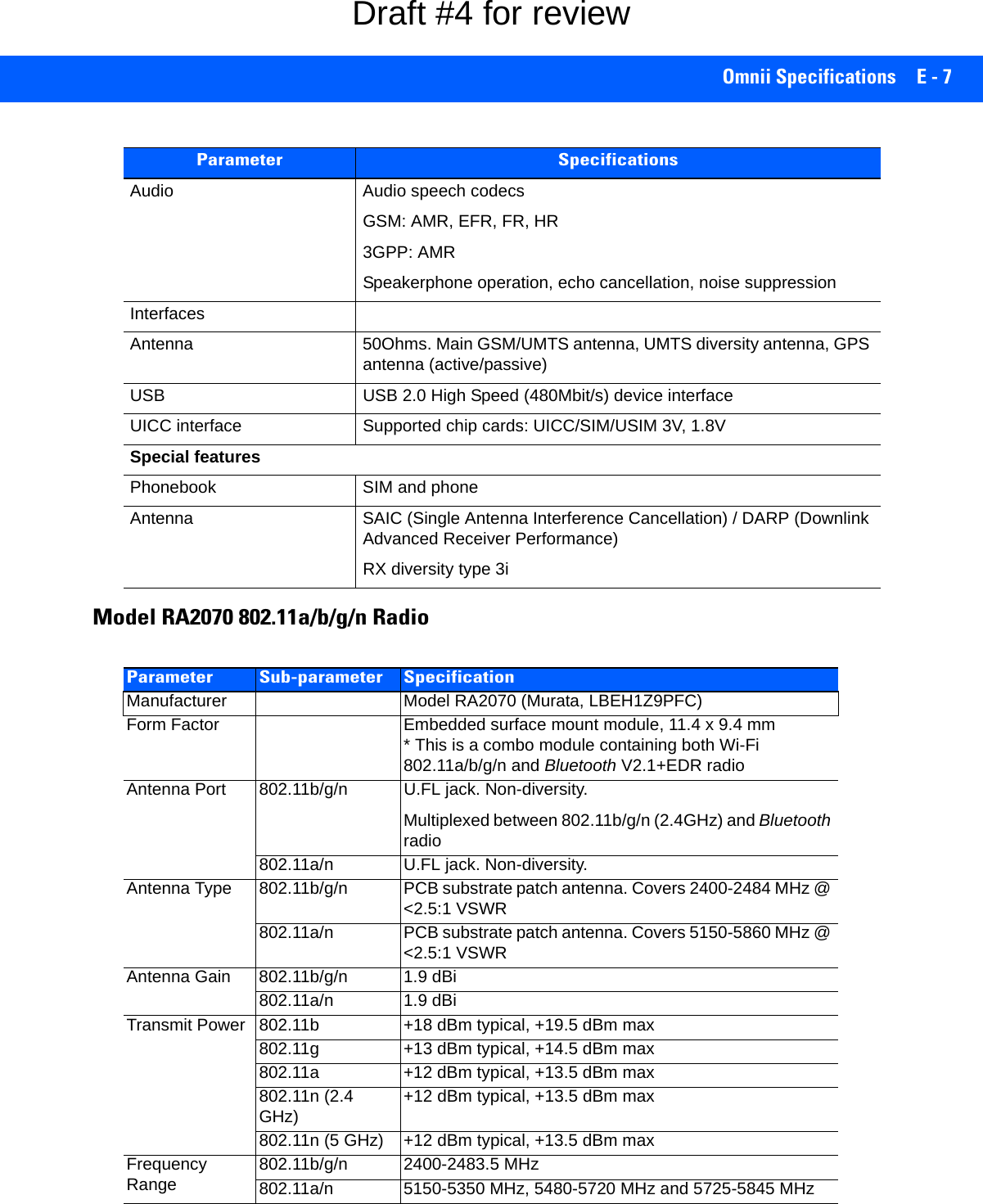
![Omnii Specifications E - 5Cinterion PH8-P GSM/GPRS/EDGE/UMTS/HSPA+ RadioVoice Triple-rate codec for HR, FR, and EFRAdaptive multi-rate AMRBasic hands-free operationEcho cancellationNoise reduction Interfaces Hirose U.FL-R-SMT 50 ohm antenna connectorAntenna solder padMolex 80-pin board-to-board connector: Power supply Audio: 2x analog, 1x digital Serial interface (ITU-T V.24 protocol) SIM card interface 3 V, 1.8 V Parameter SpecificationParameter SpecificationsGeneralFrequency bands GSM/GPRS/EDGE: Quad band, 850/900/1800/1900MHzUMTS/HSPA+: Five band, 800/850/900/1900/2100MHzGSM class Small MSOutput power (according to Release 99) Class 4 (+33dBm ± 2dB) for EGSM850Class 4 (+33dBm ± 2dB) for EGSM900Class 1 (+30dBm ± 2dB) for GSM1800Class 1 (+30dBm ± 2dB) for GSM1900Class E2 (+27dBm ± 3dB) for GSM 850 8-PSKClass E2 (+27dBm ± 3dB) for GSM 900 8-PSKClass E2 (+26dBm +3 /-4dB) for GSM 1800 8-PSKClass E2 (+26dBm +3 /-4dB) for GSM 1900 8-PSKClass 3 (+24dBm +1/-3dB) for UMTS 2100, WCDMA FDD Bd IClass 3 (+24dBm +1/-3dB) for UMTS 1900,WCDMA FDD Bd IIClass 3 (+24dBm +1/-3dB) for UMTS 900, WCDMA FDD Bd VIIIClass 3 (+24dBm +1/-3dB) for UMTS 850, WCDMA FDD Bd VClass 3 (+24dBm +1/-3dB) for UMTS 800, WCDMA FDD Bd VIHSPA features3GPP Release 6, 7 DL 14.4Mbps, UL 5.7MbpsUE CAT. [1-6], 11, 12 supportedCompressed mode (CM) supported according to 3GPP TS25.212Draft #4 for review](https://usermanual.wiki/Symbol-Technologies/RA1202.User-Manual-2of2/User-Guide-2406596-Page-77.png)

![F - 4 Omnii Hand-Held Computer with Windows CE 6.0 User Guide• Storage Temperature: -40°C to +60°C (-40°F to +140°F)• Humidity: Condensing (condensation-free using internal heaters)• Rain/Dust: IP65, IP67, IEC 60759• Drop Rating: Multiple 2 m (6.5 ft) drops to polished concrete• ESD: +/- 8 kV contact, +/- 15 kV air discharge. Regulatory Approvals• Worldwide Safety, EMC, RF, Laser approvals• CE Mark• E Mark (vehicle cradles)• RoHS compliant• WEEE compliant• REACH compliantThe Freezer KeyboardsTwo keyboard layouts are available for the Chiller and Arctic hand-held units. Both variants include specially designed keyboards that resist freezing due to ice build-up in condensing environments.Figure F-2Freezer Keyboard Layouts34-Key Numeric Keyboard58-Key Full Alpha Numeric Keyboard[FN] Modifier key[SYM] key[SHIFT] [SCAN] Key[Enter/Power] [Windows] keyModifier key key[FN] KeysDraft #4 for review](https://usermanual.wiki/Symbol-Technologies/RA1202.User-Manual-2of2/User-Guide-2406596-Page-86.png)

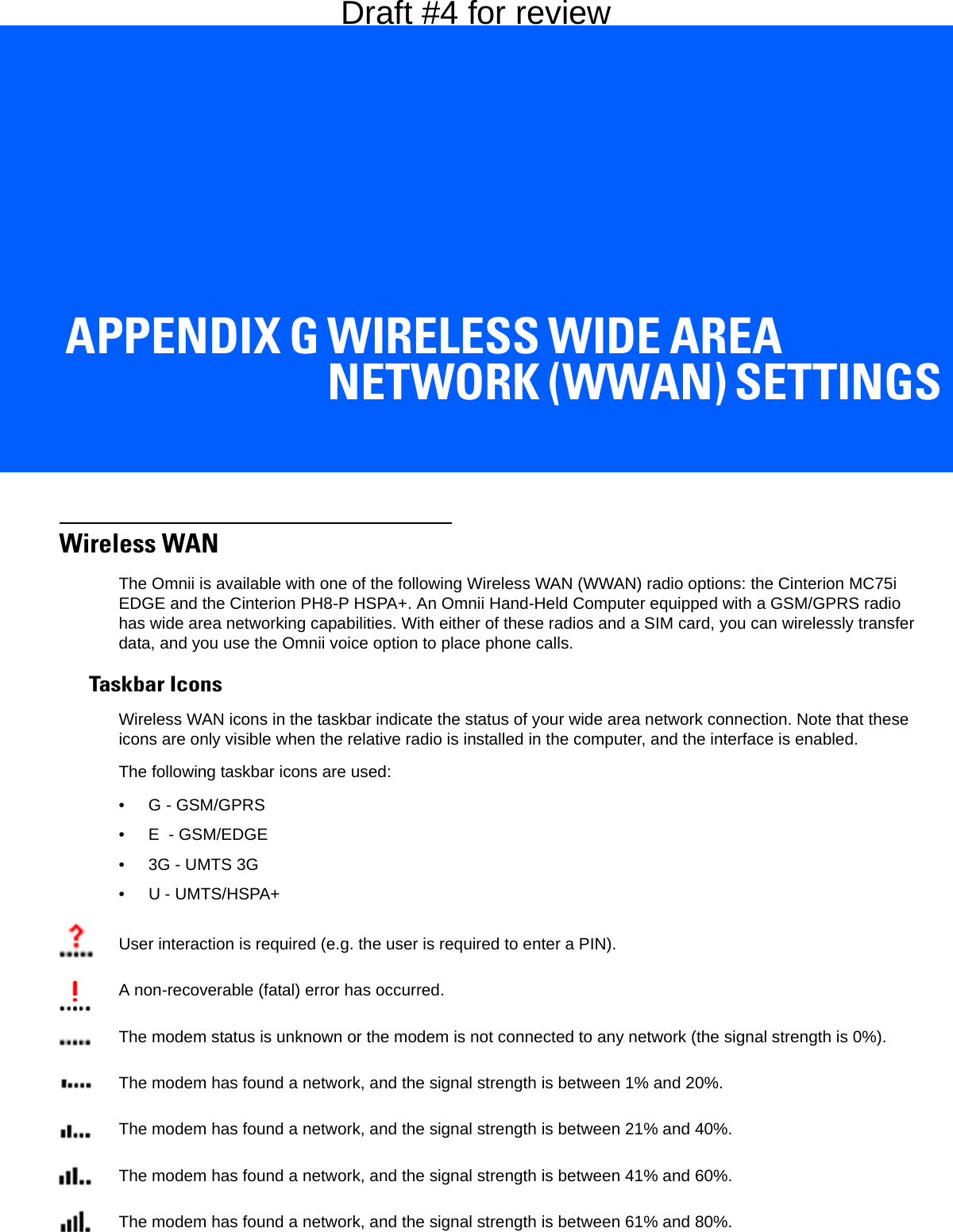
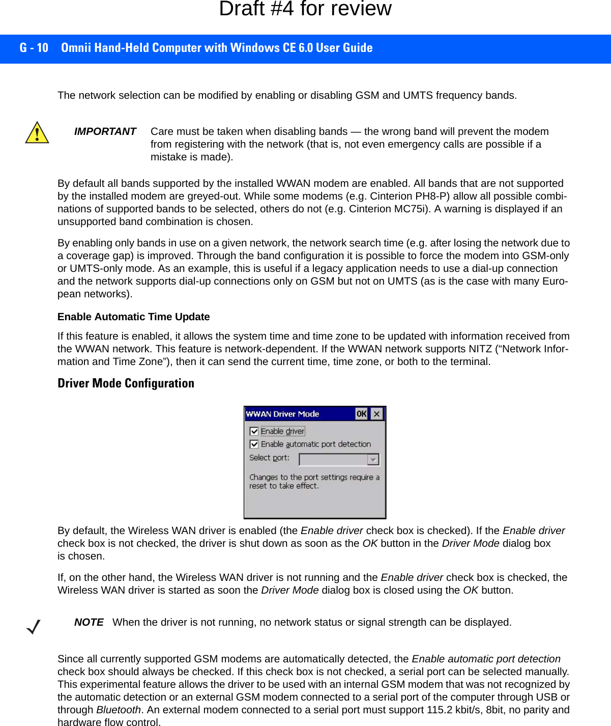
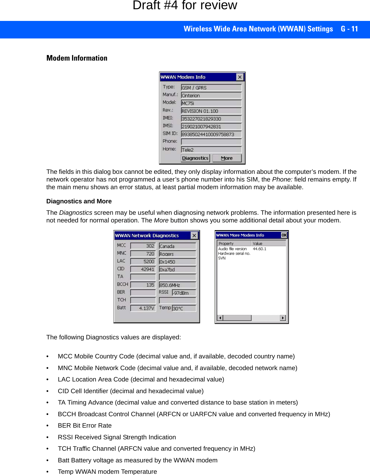
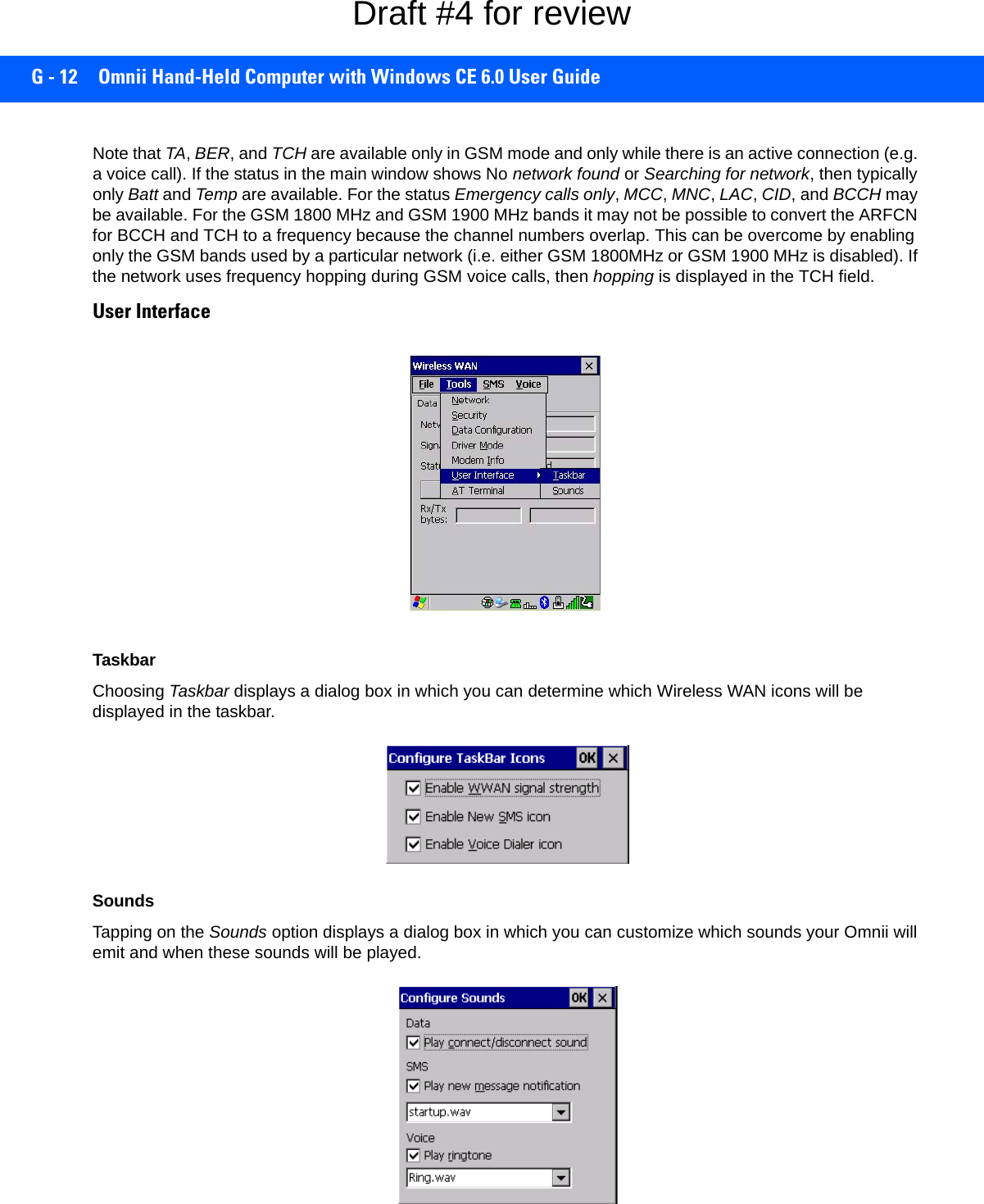
![G - 4 Omnii Hand-Held Computer with Windows CE 6.0 User GuideAdvanced InformationIn most cases, when a GSM/GPRS radio and SIM are installed in your computer, setup is automatic. Follow the steps outlined under the heading Establishing a Packet Data Connection on page G-2 to make a connec-tion. The information in this section is for advanced setup purposes.Entering a PIN NumberIf a PIN is required, a PIN entry dialog box is displayed.• Type your PIN, and press [Enter].Once the correct PIN or PUK is entered or if none was required, the modem is instructed to perform a GSM network registration followed by a GPRS attach. The main Wireless WAN dialog box reflects the progress of the initialization.• Searching for modem.• Initializing modem.• SIM is ready.• Searching for network.• Registered on network.• Searching for GPRS.• Ready to connect.If the modem loses the connection to the GSM network, the following states are repeated: Searching for network, Registered on network, Searching for packet data, and Ready to connect. Error StatesThe following temporary error states (i.e., these states may disappear without interaction) may be displayed:• Emergency calls only. The modem has found a network but is not allowed to register (e.g. no roaming agreement between net-works). The modem keeps searching for another network.• No network found. A network is not currently available. The modem continues searching for a network.• Packet data not available. The current network does not support a packet data service.• Packet data not allowed. The modem is not allowed to use the packet data service on the current network (e.g. no GPRS roaming agreement between network; a roaming agreement for voice may still be in place). It is also possible that you do not have a subscription for GPRS at all.The remaining error states are permanent:• SIM is missing. The SIM card is missing. After the SIM has been inserted a warm boot may be required.• SIM failure. NOTE If you exceed the number of allowable attempts, a PUK entry window is brought to the fore-ground. You’ll need to enter a new PIN number.Draft #4 for review](https://usermanual.wiki/Symbol-Technologies/RA1202.User-Manual-2of2/User-Guide-2406596-Page-96.png)
![Wireless Zero Config Settings H - 5•Saving and exiting the radio setup: Once you’ve completed the configuration, press [Enter], or tap on OK.The connection you created will be listed in the Wireless Information tab as a preferred network. The radio will search for the SSID and compare the WEP and authentication information you specified. If there is a match between the hand-held settings and the access point settings, the hand-held will communicate on the network through the access point.Assigning An IP AddressIf your network is not using a DHCP server, you will need to assign an IP address. Refer to IP Address on page 3-82 for details about assigning an IP address. Name ServerRefer to Name Server on page 3-83 for details about this option.Advanced FeaturesTo display the Advanced Wireless Settings dialog box:• Tap on the Advanced button in the Wireless Information tab. (Refer to Figure H-3 Wireless Information.) This window lists the available preferred networks.Figure H-6Advanced Wireless SettingsRearranging Preferred NetworksThe Omnii attempts to connect with the networks listed in this dialog box in sequence, beginning at the top of the list. If you need to rearrange this list of networks — move networks up and down in the list:•Tap in the Networks List, and highlight the network that you want to move up or down in the list.• To move the highlighted item in the list upward or downward, tap on the Up or Down button.Deleting A Preferred NetworkTo delete a network from this list:• In the preferred networks list, highlight the network you want to remove.• Tap on the Delete button.Draft #4 for review](https://usermanual.wiki/Symbol-Technologies/RA1202.User-Manual-2of2/User-Guide-2406596-Page-111.png)
![H - 6 Omnii Hand-Held Computer with Windows CE 6.0 User GuideChanging Network PropertiesTo change the properties of an existing preferred network:• Highlight the network that you want to modify.• Tap on the Properties button.• Make any necessary changes in the Wireless Properties dialog box, and press [Enter] to save the changes.Draft #4 for review](https://usermanual.wiki/Symbol-Technologies/RA1202.User-Manual-2of2/User-Guide-2406596-Page-112.png)