Symbol Technologies RA1202 UHF Narrowband Radio Module User Manual
Symbol Technologies Inc UHF Narrowband Radio Module
UserManual.wiki
>
Symbol Technologies
>
RA1202 User Manual
>
User Manual
Contents
1.
User Manual
2.
User Manual 1of2
3.
User Manual 2of2
4.
Regulatory Warranty Guide
User Manual
Navigation menu
Upload a User Manual
Namespaces
Wiki Guide
HTML
PDF
Info
Views
User Manual
Discussion / Help
Navigation
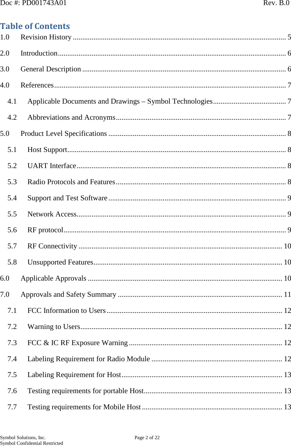
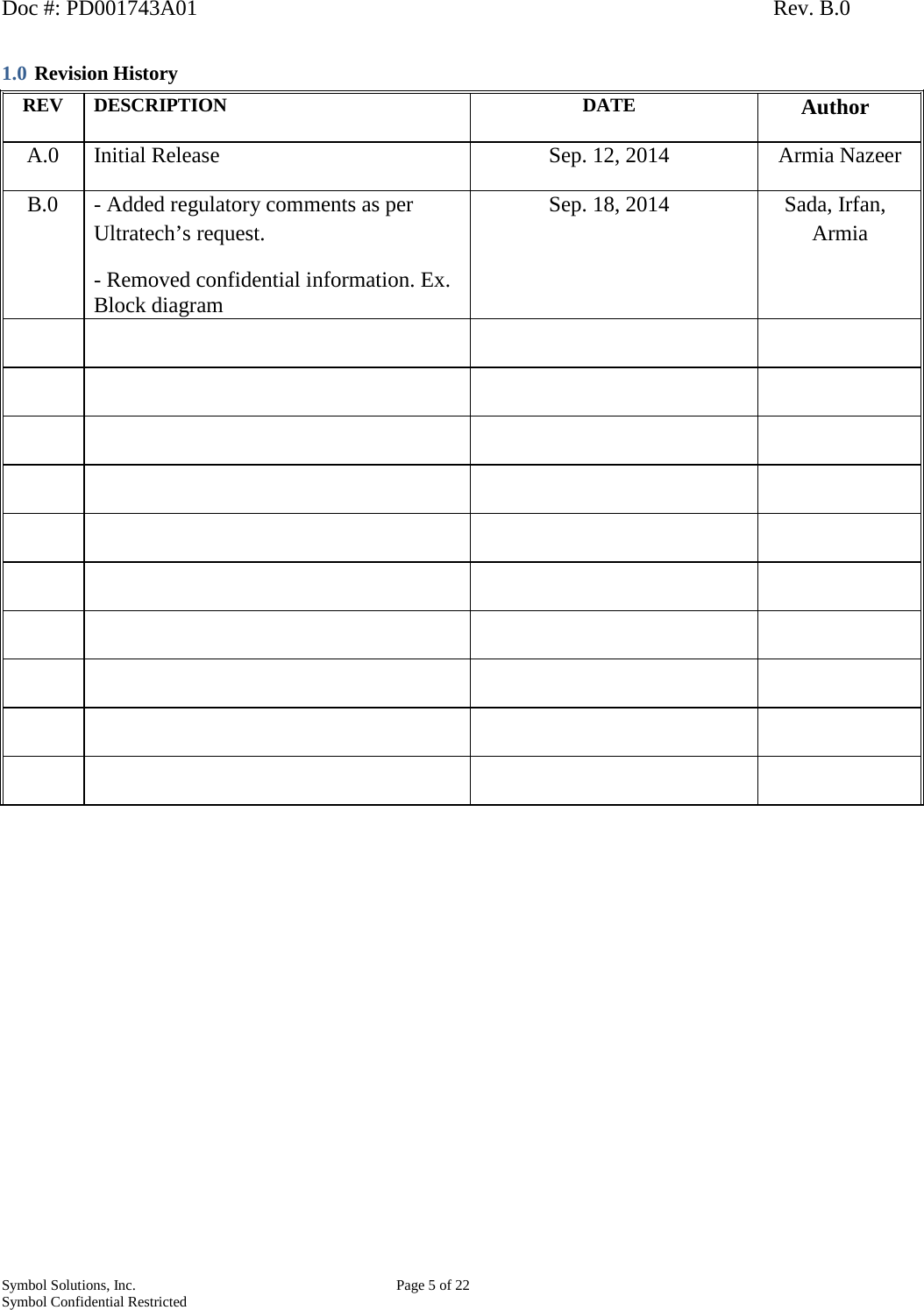
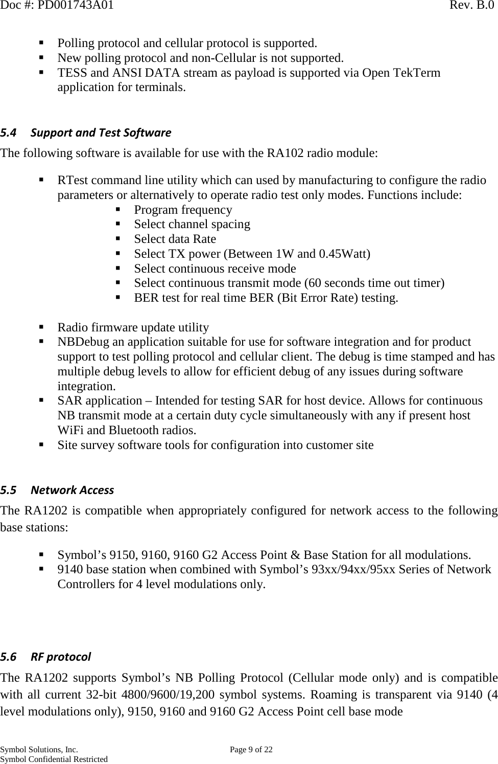
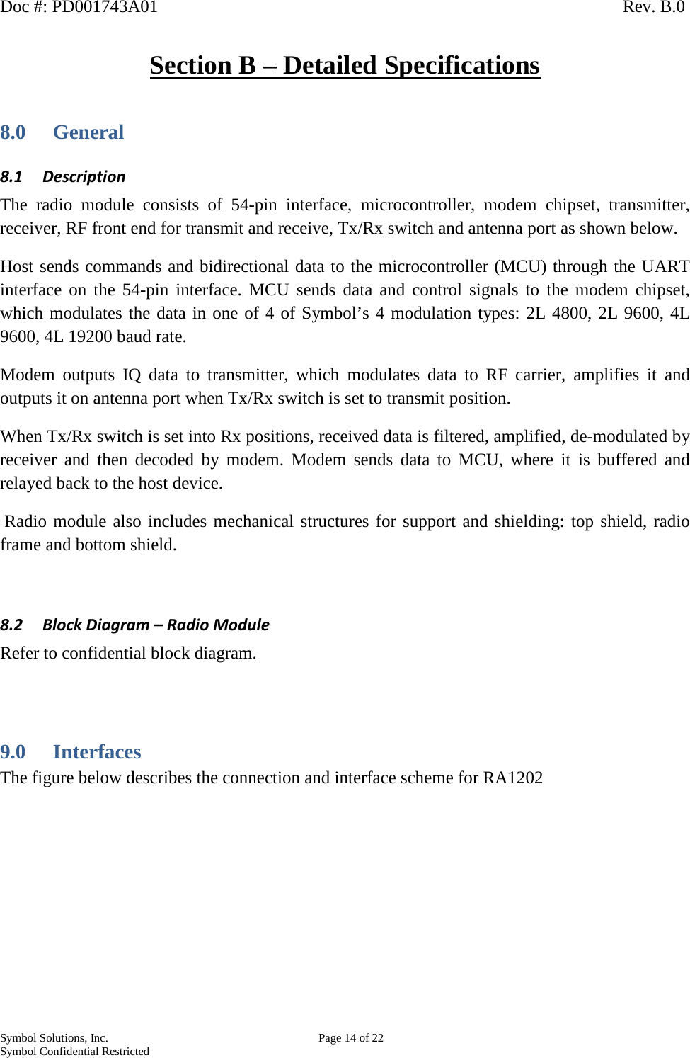
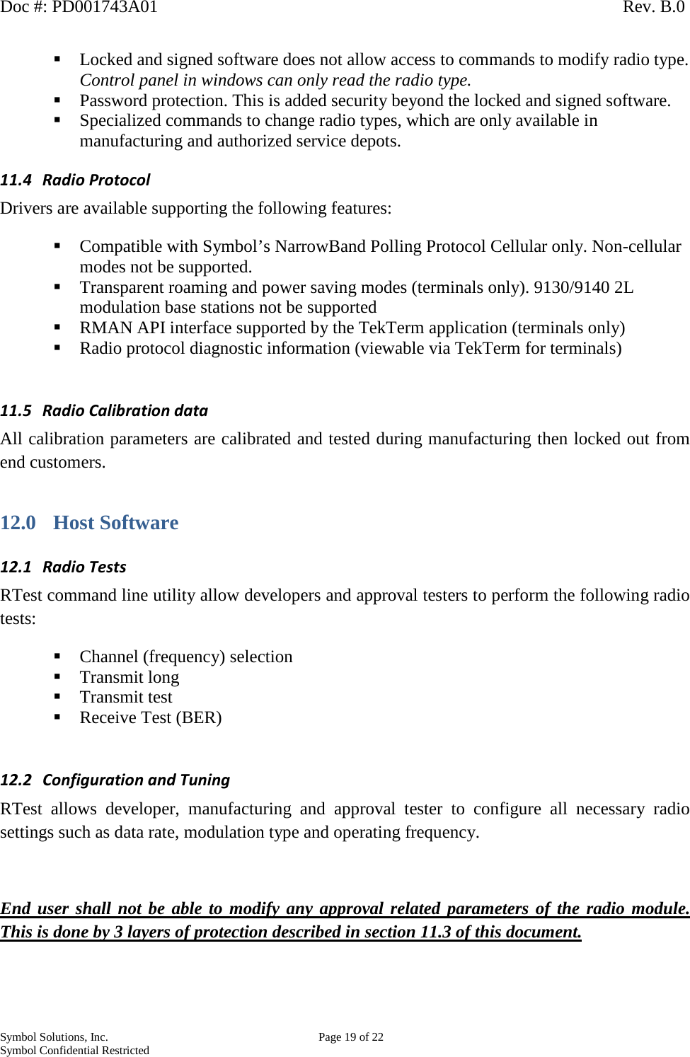
![Doc #: PD001743A01 Rev. B.0 Symbol Solutions, Inc. Page 10 of 22 Symbol Confidential Restricted 5.7 RF Connectivity Frequency range: - 403 - 435 MHz, 435 – 470 MHz Data rate & modeError! Bookmark not defined.: 2 level FSK 4800 bps, 1 2 level FSK 9600 bps 4 level FSK 9600 bps 4 level FSK 19.2 Kbps RF Power: Factory set to 0.45 watt (non-US) or 1 watt Channel Spacing: 12.5 KHz 20 KHz (non-US & Canada) 25 KHz (not for Part 90) Sensitivity2: 0.5uV nominal @ 1% BER [12.5 kHz] or better 0.7uV nominal @ 1% BER [20/25 kHz] or better 5.8 Unsupported Features The following features are not supported by the RA1202 radio module: TelkTalk is not supported. Intrinsically Safe is not supported Formal MTBF – Formal calculations to MIL-HDBK-217F will not be provided Non-cellular protocol is not supported Not backward compatible to 9130 and 9140 base stations for 2 level modulations only. 6.0 Applicable Approvals The RA1202 is pending submission for approval for the following certifications: i. FCC Compliance and Approval a. Modular compliance and approval as per CFR47 Part 90, 22, 74, 80 and Part 15. ii. Industry Canada Compliance and Approval 1 Effective peak data rate 2 Above are radio module only receiver sensitivity outside of a host. Host receiver sensitivity depends on host EMC characteristics.](https://usermanual.wiki/Symbol-Technologies/RA1202.User-Manual/User-Guide-2401246-Page-10.png)
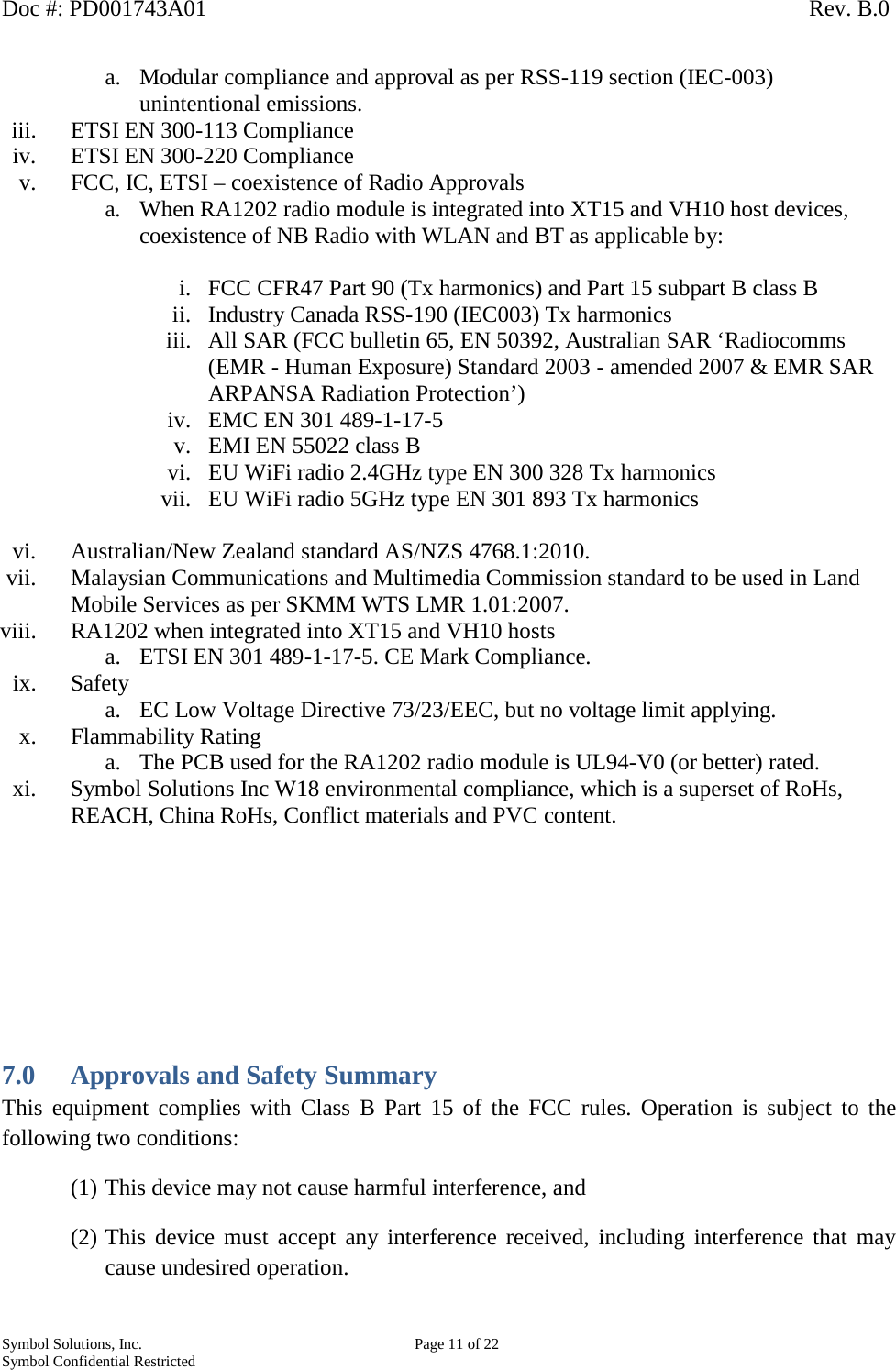
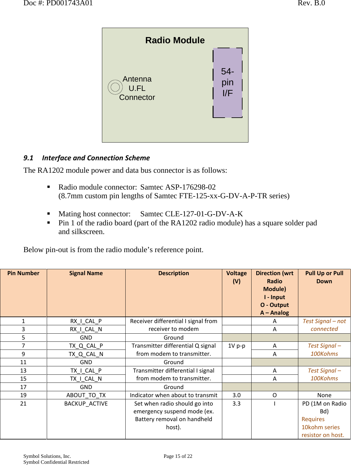
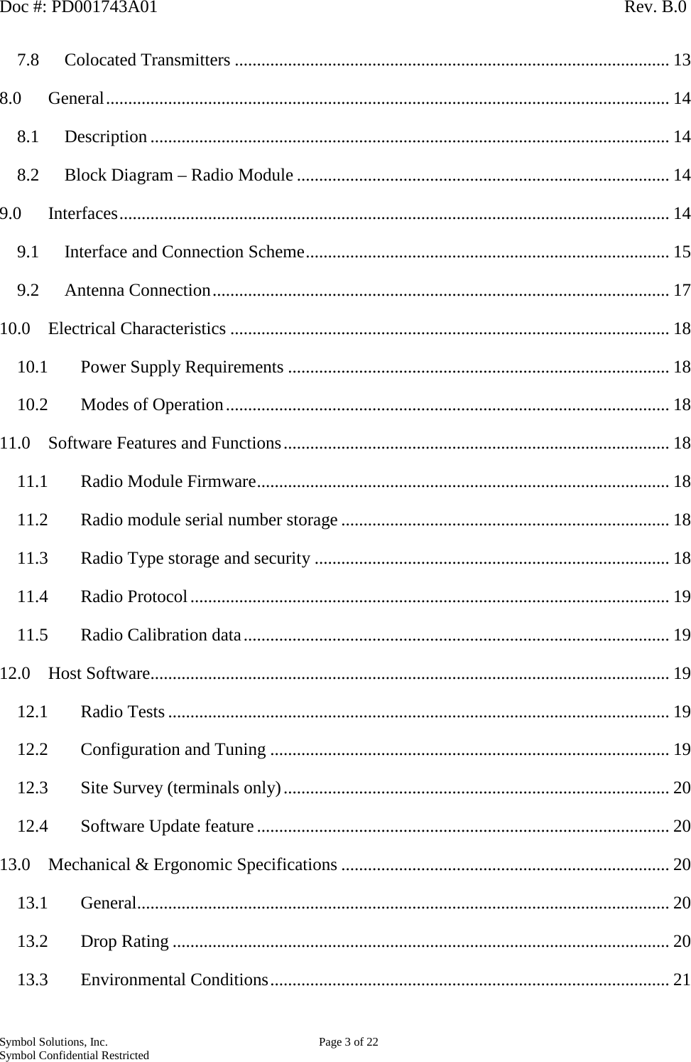
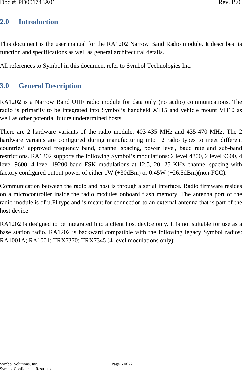
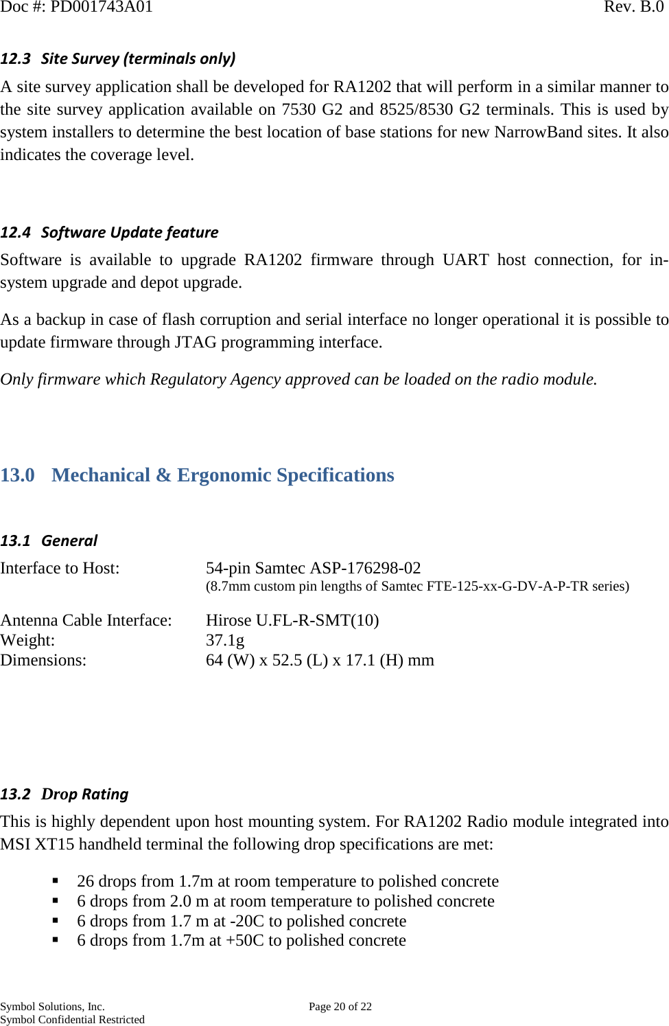
![Doc #: PD001743A01 Rev. B.0 Symbol Solutions, Inc. Page 17 of 22 Symbol Confidential Restricted Pin Number Signal Name Description Voltage (V) Direction (wrt Radio Module) I - Input O - Output A – Analog Pull Up or Pull Down 2 RX_Q_CAL_N Receiver differential Q signal from receiver to modem A Test Signal – not connected 4 RX_Q_CAL_P O 6 GND Ground 8 UPS_MODE Indicator from Host to MCU -radio to go into lower power mode. 3.0 I PD (100k on Radio Board) Future feature to be implemented 10 NOT USED 12 NOT USED 14 GND Ground 16 TX_ON (RF_PA_GATE_EN) TX trigger signal from modem for test equipment. O 18 GND Ground 20 SYMBOL_CLK Symbol clock from modem chipset 3.0 O Test Signal – not connected 22 GND Ground 24 MCU_UART3_TX MCU serial port 3 (MCU program and debug) 3.0 O 26 MCU_UART3_RX 3.0 I 28 GND Ground 30 MCU_BOOT1 ** MCU boot configuration 3.0 I PD (100K on Radio Board) 32 MCU_BOOT0 ** 34 MCU_RST_N MCU reset control signal PD (100K on Radio Board) 36 GND 38 DO NOT USE 40 JTAG_TCK JTAG clock to the MCU. 3.0 I PD (INT) 42 JTAG_TDI/SPI3_NCC JTAG shared as SPI CS 3.0 O None 44 JTAG_TDO/MCU_HRTBEAT JTAG shared as debug signal 3.0 O None 46 DO NOT USED 48 GND Ground 50 JTAG_TMS/SPARE-1 JTAG shared as Spare GPIO 3.0 Undefined None 52 MCU_SPARE_3 Spare GPIO 3.0 Undefined None ** MCU_BOOT[1:0] = x0 MCU boot from MCU flash memory MCU_BOOT[1:0] = 01 MCU boot from system memory MCU_BOOT[1:0] = 11 MCU boot from Embedded SRAM 9.2 Antenna Connection Connector: Hirose U.FL-R-SMT(10) Antenna: 50 Ohm nominal impedance; external only, via interconnecting RF cable. Recommend having a ferrite choke on RF antenna cable.](https://usermanual.wiki/Symbol-Technologies/RA1202.User-Manual/User-Guide-2401246-Page-17.png)
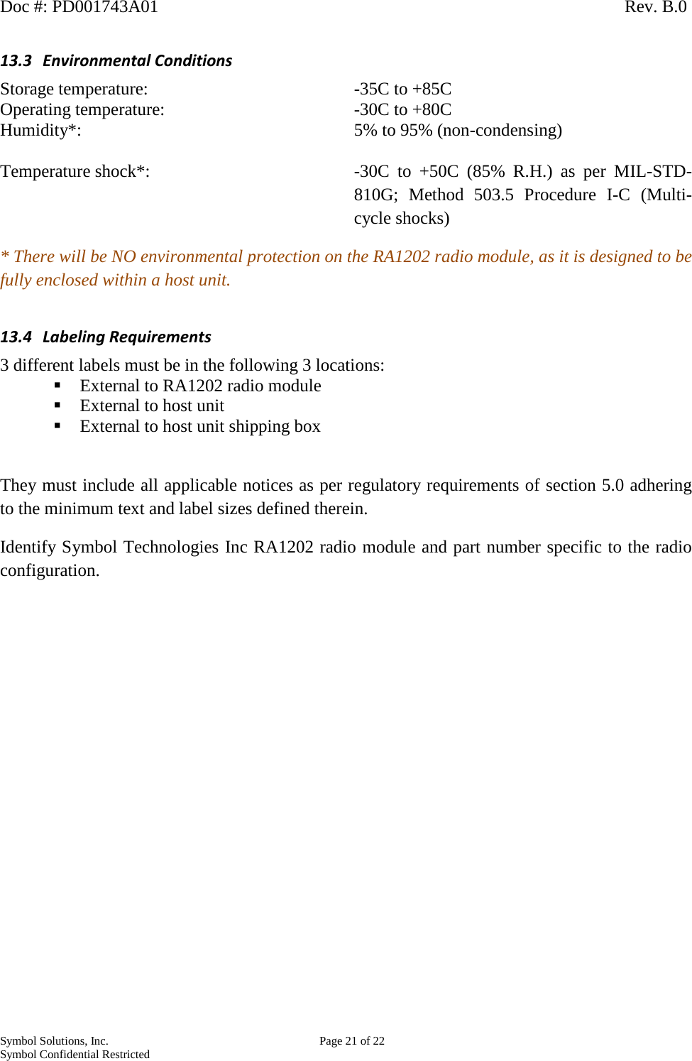
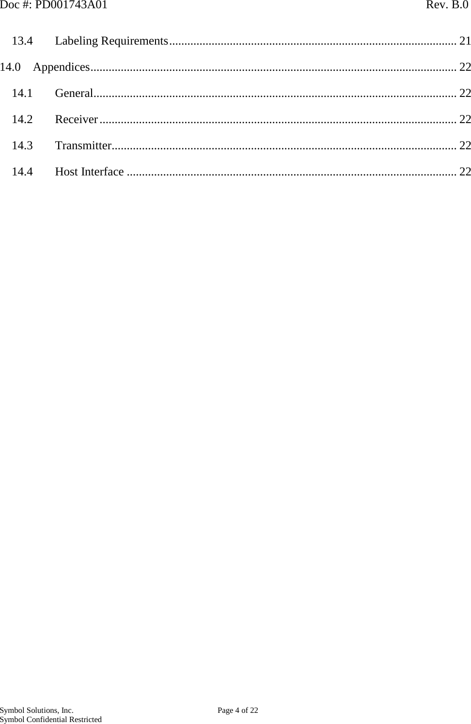
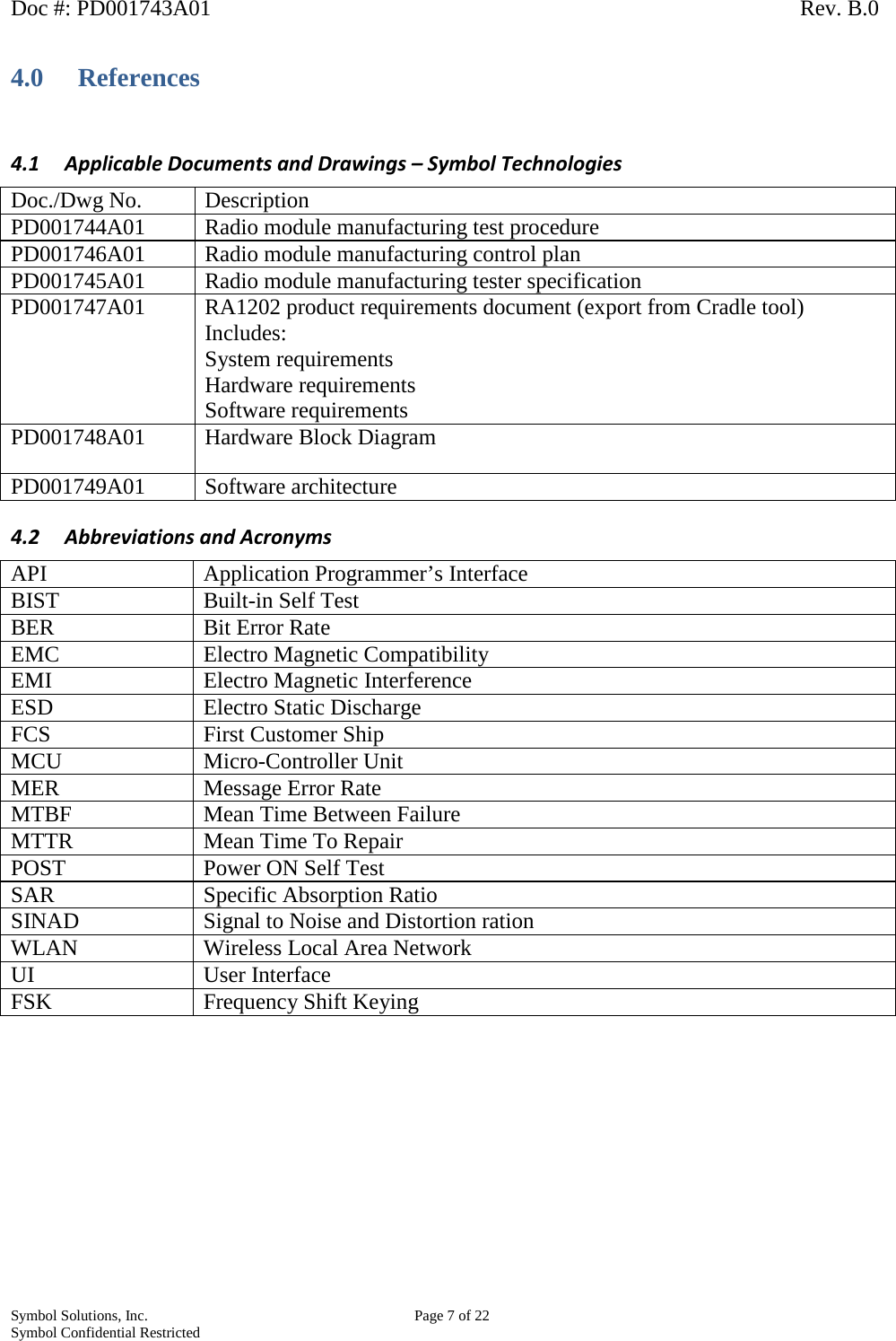
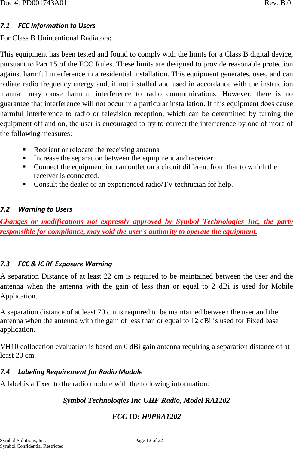
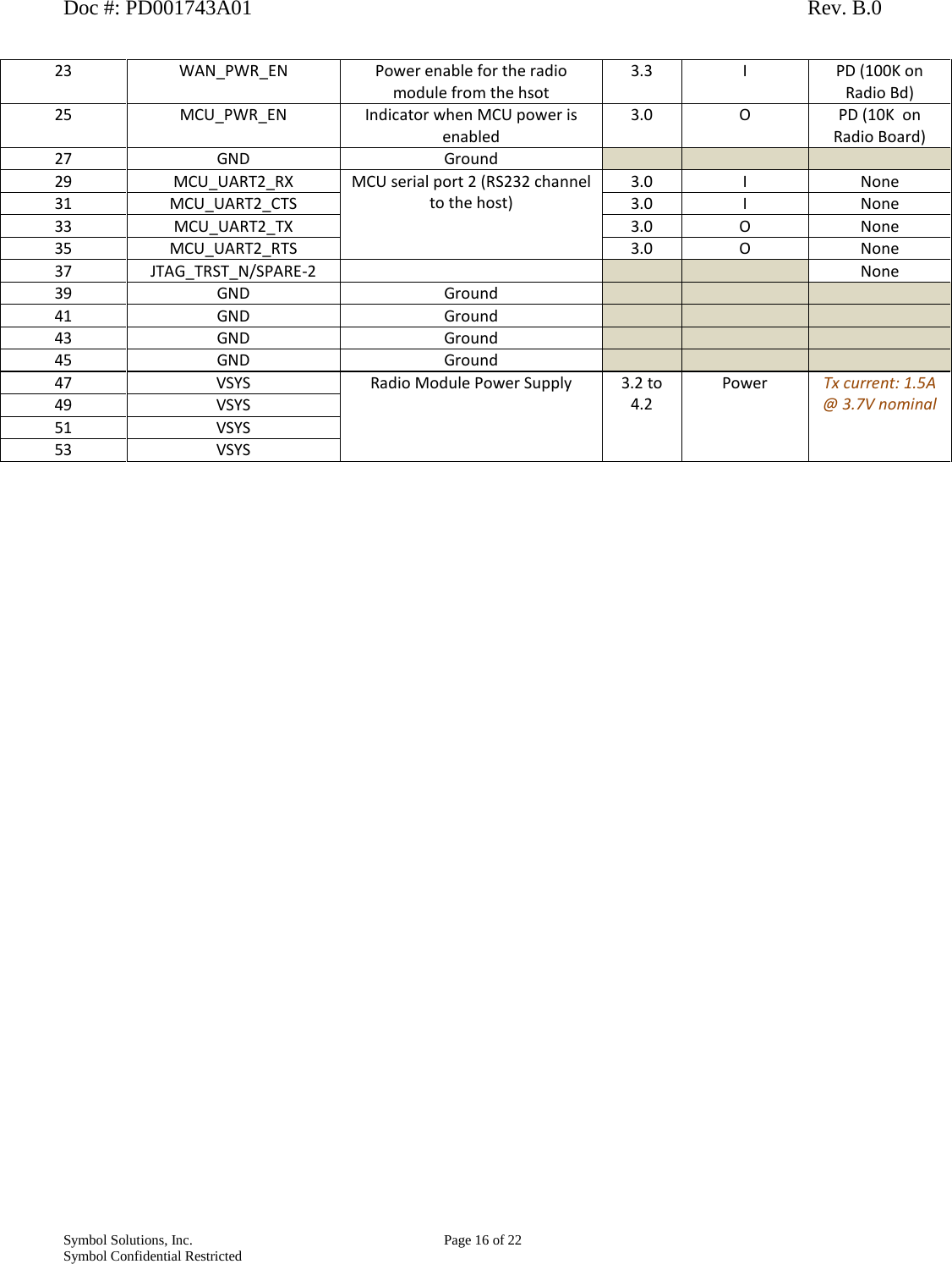
![Doc #: PD001743A01 Rev. B.0 Symbol Solutions, Inc. Page 22 of 22 Symbol Confidential Restricted 14.0 Appendices Radio Performance Specifications 14.1 General Frequency Range: 435-470 MHz [high band – FCC, IC, EU, & other] 403-435 MHz [low band – non-FCC, non-IC] Frequency Control: Synthesized Channel Spacing: 12.5 kHz [FCC & others] 20 kHz [non-FCC] 25 kHz non Part 90 Mode of Operation: Simplex or Half Duplex Regulated Supply Voltage: 3.7VDC +/- 15% Operating Temperature Range: -30C to +80C Maximum Dimensions: 64 (W) x 52.5 (L) x 17.1 (H) mm Weight: 37.1g FCC Compliance: Yes [high band only – 435-470 MHz] No [low band] 14.2 Receiver Bandwidth: 35 MHz [high band] 32 MHz [low band] Frequency Stability: +/- 1ppm [-30C to + 80C] Digital Sensitivity 0.4uV at 1% BER [at 12.5 kHz channel spacing] as per ETSI EN300 113-1 v 1.7.1 RF Input Impedance 50 ohms Selectivity -61 dB [12.5 kHz channel spacing] Spurious Rejection 88 dB Intermodulation -70dB Conducted Spurious 85 dB Receive Current Drain 200 mA Receive Attach Time < 3.5 msec 14.3 Transmitter Bandwidth: 35 MHz [high band] 32 MHz [low band] Frequency Stability: +/- 1ppm [-30C to + 80C] TCXO coupling AC RF Output Power 1W nominal 0.5W [available for non-FCC variant] RF Output Impedance 50 ohms Modulation Distortion < 3% Maximum Duty Cycle 30%, 60 seconds maximum continuous transmit time Transmitter Attack Time < 3.5 msec Spurious & Harmonic FM -79 dB Transmit Current Drain 1.5A at 3.7 VDC nominal 14.4 Host Interface Data Input Impedance 100 Kohms](https://usermanual.wiki/Symbol-Technologies/RA1202.User-Manual/User-Guide-2401246-Page-22.png)