Symbol Technologies RA1202 UHF Narrowband Radio Module User Manual
Symbol Technologies Inc UHF Narrowband Radio Module
Contents
User Manual

RA1202 User Manual
Narrow Band UHF Radio
Symbol Technologies Inc.
RA1202 User Manual
DOC. NO: PD001743A01
SHEET 1 OF 44 REVISION : B.0
Doc #: PD001743A01 Rev. B.0
Symbol Solutions, Inc. Page 2 of 22
Symbol Confidential Restricted
Table of Contents
1.0 Revision History .................................................................................................................. 5
2.0 Introduction .......................................................................................................................... 6
3.0 General Description ............................................................................................................. 6
4.0 References ............................................................................................................................ 7
4.1 Applicable Documents and Drawings – Symbol Technologies ....................................... 7
4.2 Abbreviations and Acronyms ........................................................................................... 7
5.0 Product Level Specifications ............................................................................................... 8
5.1 Host Support ..................................................................................................................... 8
5.2 UART Interface ................................................................................................................ 8
5.3 Radio Protocols and Features ........................................................................................... 8
5.4 Support and Test Software ............................................................................................... 9
5.5 Network Access................................................................................................................ 9
5.6 RF protocol ....................................................................................................................... 9
5.7 RF Connectivity ............................................................................................................. 10
5.8 Unsupported Features ..................................................................................................... 10
6.0 Applicable Approvals ........................................................................................................ 10
7.0 Approvals and Safety Summary ........................................................................................ 11
7.1 FCC Information to Users .............................................................................................. 12
7.2 Warning to Users ............................................................................................................ 12
7.3 FCC & IC RF Exposure Warning .................................................................................. 12
7.4 Labeling Requirement for Radio Module ...................................................................... 12
7.5 Labeling Requirement for Host ...................................................................................... 13
7.6 Testing requirements for portable Host .......................................................................... 13
7.7 Testing requirements for Mobile Host ........................................................................... 13
Doc #: PD001743A01 Rev. B.0
Symbol Solutions, Inc. Page 3 of 22
Symbol Confidential Restricted
7.8 Colocated Transmitters .................................................................................................. 13
8.0 General ............................................................................................................................... 14
8.1 Description ..................................................................................................................... 14
8.2 Block Diagram – Radio Module .................................................................................... 14
9.0 Interfaces ............................................................................................................................ 14
9.1 Interface and Connection Scheme .................................................................................. 15
9.2 Antenna Connection ....................................................................................................... 17
10.0 Electrical Characteristics ................................................................................................... 18
10.1 Power Supply Requirements ...................................................................................... 18
10.2 Modes of Operation .................................................................................................... 18
11.0 Software Features and Functions ....................................................................................... 18
11.1 Radio Module Firmware ............................................................................................. 18
11.2 Radio module serial number storage .......................................................................... 18
11.3 Radio Type storage and security ................................................................................ 18
11.4 Radio Protocol ............................................................................................................ 19
11.5 Radio Calibration data ................................................................................................ 19
12.0 Host Software..................................................................................................................... 19
12.1 Radio Tests ................................................................................................................. 19
12.2 Configuration and Tuning .......................................................................................... 19
12.3 Site Survey (terminals only) ....................................................................................... 20
12.4 Software Update feature ............................................................................................. 20
13.0 Mechanical & Ergonomic Specifications .......................................................................... 20
13.1 General ........................................................................................................................ 20
13.2 Drop Rating ................................................................................................................ 20
13.3 Environmental Conditions .......................................................................................... 21
Doc #: PD001743A01 Rev. B.0
Symbol Solutions, Inc. Page 4 of 22
Symbol Confidential Restricted
13.4 Labeling Requirements ............................................................................................... 21
14.0 Appendices ......................................................................................................................... 22
14.1 General ........................................................................................................................ 22
14.2 Receiver ...................................................................................................................... 22
14.3 Transmitter.................................................................................................................. 22
14.4 Host Interface ............................................................................................................. 22

Doc #: PD001743A01 Rev. B.0
Symbol Solutions, Inc. Page 5 of 22
Symbol Confidential Restricted
1.0 Revision History
REV
DESCRIPTION
DATE
Author
A.0
Initial Release
Sep. 12, 2014
Armia Nazeer
B.0
- Added regulatory comments as per
Ultratech’s request.
- Removed confidential information. Ex.
Block diagram
Sep. 18, 2014
Sada, Irfan,
Armia
Doc #: PD001743A01 Rev. B.0
Symbol Solutions, Inc. Page 6 of 22
Symbol Confidential Restricted
2.0 Introduction
This document is the user manual for the RA1202 Narrow Band Radio module. It describes its
function and specifications as well as general architectural details.
All references to Symbol in this document refer to Symbol Technologies Inc.
3.0 General Description
RA1202 is a Narrow Band UHF radio module for data only (no audio) communications. The
radio is primarily to be integrated into Symbol’s handheld XT15 and vehicle mount VH10 as
well as other potential future undetermined hosts.
There are 2 hardware variants of the radio module: 403-435 MHz and 435-470 MHz. The 2
hardware variants are configured during manufacturing into 12 radio types to meet different
countries’ approved frequency band, channel spacing, power level, baud rate and sub-band
restrictions. RA1202 supports the following Symbol’s modulations: 2 level 4800, 2 level 9600, 4
level 9600, 4 level 19200 baud FSK modulations at 12.5, 20, 25 KHz channel spacing with
factory configured output power of either 1W (+30dBm) or 0.45W (+26.5dBm)(non-FCC).
Communication between the radio and host is through a serial interface. Radio firmware resides
on a microcontroller inside the radio modules onboard flash memory. The antenna port of the
radio module is of u.Fl type and is meant for connection to an external antenna that is part of the
host device
RA1202 is designed to be integrated into a client host device only. It is not suitable for use as a
base station radio. RA1202 is backward compatible with the following legacy Symbol radios:
RA1001A; RA1001; TRX7370; TRX7345 (4 level modulations only);

Doc #: PD001743A01 Rev. B.0
Symbol Solutions, Inc. Page 7 of 22
Symbol Confidential Restricted
4.0 References
4.1 Applicable Documents and Drawings – Symbol Technologies
Doc./Dwg No.
Description
PD001744A01
Radio module manufacturing test procedure
PD001746A01
Radio module manufacturing control plan
PD001745A01
Radio module manufacturing tester specification
PD001747A01
RA1202 product requirements document (export from Cradle tool)
Includes:
System requirements
Hardware requirements
Software requirements
PD001748A01
Hardware Block Diagram
PD001749A01
Software architecture
4.2 Abbreviations and Acronyms
API
Application Programmer’s Interface
BIST
Built-in Self Test
BER
Bit Error Rate
EMC
Electro Magnetic Compatibility
EMI
Electro Magnetic Interference
ESD
Electro Static Discharge
FCS
First Customer Ship
MCU
Micro-Controller Unit
MER
Message Error Rate
MTBF
Mean Time Between Failure
MTTR
Mean Time To Repair
POST
Power ON Self Test
SAR
Specific Absorption Ratio
SINAD
Signal to Noise and Distortion ration
WLAN
Wireless Local Area Network
UI
User Interface
FSK
Frequency Shift Keying
Doc #: PD001743A01 Rev. B.0
Symbol Solutions, Inc. Page 8 of 22
Symbol Confidential Restricted
5.0 Product Level Specifications
The RA1202 provides narrowband data communications using legacy Symbol proprietary
narrowband protocol and FM modulation schemes. These include:
2 level FSK running at 4800 and 9600 bps
4 level FSK running at 9600 and 19,200 bps
The RA1202 is functionally backward compatible for all modulations with currently existing
Symbol narrowband radios including RA1001A; RA1001; TRX7370, TRX7355 (4 level
modulations only).
The implementation of the RA1202 is modular and is meant for integration in Symbol’s XT15
handheld and VH10 vehicle mount terminals as well a future potential host device. For a usable
radio system an external antenna system, antenna feed cable and data and power interface board
will be necessary for integration with any target host as required, the design of which shall not be
covered under this specification.
An interface board is necessary to provide conversion of host power from host voltage to
required radio voltage as well as for providing appropriate mechanical connection between the
host device and the radio, and for data interconnect.
5.1 Host Support
RA1202 is initially intended to be integrated into the following hosts:
XT15 handheld terminal with WinCE 6.0 operating system
VH10 vehicle mount terminal with WinCE 6.0 operating system
The open architecture of RA1202 is designed to allow ease of integration with any potential
future host devices by limiting the connection to single power supply and communications bus
(RS232 UART serial interface). In addition to electro-mechanical integration a driver will be
required for using the radio module in alternate operating systems such as but not limited to
Windows CE 7 and Windows 7.
5.2 UART Interface
A UART interface is required for communication between the host and the radio.
5.3 Radio Protocols and Features
The following protocols are supported by the RA1202:
Doc #: PD001743A01 Rev. B.0
Symbol Solutions, Inc. Page 9 of 22
Symbol Confidential Restricted
Polling protocol and cellular protocol is supported.
New polling protocol and non-Cellular is not supported.
TESS and ANSI DATA stream as payload is supported via Open TekTerm
application for terminals.
5.4 Support and Test Software
The following software is available for use with the RA102 radio module:
RTest command line utility which can used by manufacturing to configure the radio
parameters or alternatively to operate radio test only modes. Functions include:
Program frequency
Select channel spacing
Select data Rate
Select TX power (Between 1W and 0.45Watt)
Select continuous receive mode
Select continuous transmit mode (60 seconds time out timer)
BER test for real time BER (Bit Error Rate) testing.
Radio firmware update utility
NBDebug an application suitable for use for software integration and for product
support to test polling protocol and cellular client. The debug is time stamped and has
multiple debug levels to allow for efficient debug of any issues during software
integration.
SAR application – Intended for testing SAR for host device. Allows for continuous
NB transmit mode at a certain duty cycle simultaneously with any if present host
WiFi and Bluetooth radios.
Site survey software tools for configuration into customer site
5.5 Network Access
The RA1202 is compatible when appropriately configured for network access to the following
base stations:
Symbol’s 9150, 9160, 9160 G2 Access Point & Base Station for all modulations.
9140 base station when combined with Symbol’s 93xx/94xx/95xx Series of Network
Controllers for 4 level modulations only.
5.6 RF protocol
The RA1202 supports Symbol’s NB Polling Protocol (Cellular mode only) and is compatible
with all current 32-bit 4800/9600/19,200 symbol systems. Roaming is transparent via 9140 (4
level modulations only), 9150, 9160 and 9160 G2 Access Point cell base mode

Doc #: PD001743A01 Rev. B.0
Symbol Solutions, Inc. Page 10 of 22
Symbol Confidential Restricted
5.7 RF Connectivity
Frequency range:
- 403 - 435 MHz, 435 – 470 MHz
Data rate & modeError! Bookmark not defined.:
2 level FSK 4800 bps, 1
2 level FSK 9600 bps
4 level FSK 9600 bps
4 level FSK 19.2 Kbps
RF Power: Factory set to 0.45 watt (non-US) or 1 watt
Channel Spacing:
12.5 KHz
20 KHz (non-US & Canada)
25 KHz (not for Part 90)
Sensitivity2:
0.5uV nominal @ 1% BER [12.5 kHz] or better
0.7uV nominal @ 1% BER [20/25 kHz] or better
5.8 Unsupported Features
The following features are not supported by the RA1202 radio module:
TelkTalk is not supported.
Intrinsically Safe is not supported
Formal MTBF – Formal calculations to MIL-HDBK-217F will not be provided
Non-cellular protocol is not supported
Not backward compatible to 9130 and 9140 base stations for 2 level modulations
only.
6.0 Applicable Approvals
The RA1202 is pending submission for approval for the following certifications:
i. FCC Compliance and Approval
a. Modular compliance and approval as per CFR47 Part 90, 22, 74, 80 and Part 15.
ii. Industry Canada Compliance and Approval
1 Effective peak data rate
2 Above are radio module only receiver sensitivity outside of a host. Host receiver sensitivity depends on host EMC
characteristics.
Doc #: PD001743A01 Rev. B.0
Symbol Solutions, Inc. Page 11 of 22
Symbol Confidential Restricted
a. Modular compliance and approval as per RSS-119 section (IEC-003)
unintentional emissions.
iii. ETSI EN 300-113 Compliance
iv. ETSI EN 300-220 Compliance
v. FCC, IC, ETSI – coexistence of Radio Approvals
a. When RA1202 radio module is integrated into XT15 and VH10 host devices,
coexistence of NB Radio with WLAN and BT as applicable by:
i. FCC CFR47 Part 90 (Tx harmonics) and Part 15 subpart B class B
ii. Industry Canada RSS-190 (IEC003) Tx harmonics
iii. All SAR (FCC bulletin 65, EN 50392, Australian SAR ‘Radiocomms
(EMR - Human Exposure) Standard 2003 - amended 2007 & EMR SAR
ARPANSA Radiation Protection’)
iv. EMC EN 301 489-1-17-5
v. EMI EN 55022 class B
vi. EU WiFi radio 2.4GHz type EN 300 328 Tx harmonics
vii. EU WiFi radio 5GHz type EN 301 893 Tx harmonics
vi. Australian/New Zealand standard AS/NZS 4768.1:2010.
vii. Malaysian Communications and Multimedia Commission standard to be used in Land
Mobile Services as per SKMM WTS LMR 1.01:2007.
viii. RA1202 when integrated into XT15 and VH10 hosts
a. ETSI EN 301 489-1-17-5. CE Mark Compliance.
ix. Safety
a. EC Low Voltage Directive 73/23/EEC, but no voltage limit applying.
x. Flammability Rating
a. The PCB used for the RA1202 radio module is UL94-V0 (or better) rated.
xi. Symbol Solutions Inc W18 environmental compliance, which is a superset of RoHs,
REACH, China RoHs, Conflict materials and PVC content.
7.0 Approvals and Safety Summary
This equipment complies with Class B Part 15 of the FCC rules. Operation is subject to the
following two conditions:
(1) This device may not cause harmful interference, and
(2) This device must accept any interference received, including interference that may
cause undesired operation.

Doc #: PD001743A01 Rev. B.0
Symbol Solutions, Inc. Page 12 of 22
Symbol Confidential Restricted
7.1 FCC Information to Users
For Class B Unintentional Radiators:
This equipment has been tested and found to comply with the limits for a Class B digital device,
pursuant to Part 15 of the FCC Rules. These limits are designed to provide reasonable protection
against harmful interference in a residential installation. This equipment generates, uses, and can
radiate radio frequency energy and, if not installed and used in accordance with the instruction
manual, may cause harmful interference to radio communications. However, there is no
guarantee that interference will not occur in a particular installation. If this equipment does cause
harmful interference to radio or television reception, which can be determined by turning the
equipment off and on, the user is encouraged to try to correct the interference by one of more of
the following measures:
Reorient or relocate the receiving antenna
Increase the separation between the equipment and receiver
Connect the equipment into an outlet on a circuit different from that to which the
receiver is connected.
Consult the dealer or an experienced radio/TV technician for help.
7.2 Warning to Users
Changes or modifications not expressly approved by Symbol Technologies Inc, the party
responsible for compliance, may void the user's authority to operate the equipment.
7.3 FCC & IC RF Exposure Warning
A separation Distance of at least 22 cm is required to be maintained between the user and the
antenna when the antenna with the gain of less than or equal to 2 dBi is used for Mobile
Application.
A separation distance of at least 70 cm is required to be maintained between the user and the
antenna when the antenna with the gain of less than or equal to 12 dBi is used for Fixed base
application.
VH10 collocation evaluation is based on 0 dBi gain antenna requiring a separation distance of at
least 20 cm.
7.4 Labeling Requirement for Radio Module
A label is affixed to the radio module with the following information:
Symbol Technologies Inc UHF Radio, Model RA1202
FCC ID: H9PRA1202
Doc #: PD001743A01 Rev. B.0
Symbol Solutions, Inc. Page 13 of 22
Symbol Confidential Restricted
IC: 1549L-RA1202”
7.5 Labeling Requirement for Host
After installing the radio module in a host if the label is not visible from outside then a
separate label has to be affixed to the outside of the host with following information:
“Contains Symbol Technologies Inc UHF Radio, Model RA1202
FCC ID: H9PRA1202
IC: 1549L-RA1202”
7.6 Testing requirements for portable Host
Testing of portable 7545MBWN has been addressed pending application, for any other portable
hosts with radio module RA1202 integrated requires Class II permissive change approval.
7.7 Testing requirements for Mobile Host
RA1202 integrated in a mobile host requires testing for DoC or Certification as a Class B device.
7.8 Collocated Transmitters
Collocation with other transmitters for portable 7545MBWN has been addressed pending
application, for any other portable host new certification is required.

Doc #: PD001743A01 Rev. B.0
Symbol Solutions, Inc. Page 14 of 22
Symbol Confidential Restricted
Section B – Detailed Specifications
8.0 General
8.1 Description
The radio module consists of 54-pin interface, microcontroller, modem chipset, transmitter,
receiver, RF front end for transmit and receive, Tx/Rx switch and antenna port as shown below.
Host sends commands and bidirectional data to the microcontroller (MCU) through the UART
interface on the 54-pin interface. MCU sends data and control signals to the modem chipset,
which modulates the data in one of 4 of Symbol’s 4 modulation types: 2L 4800, 2L 9600, 4L
9600, 4L 19200 baud rate.
Modem outputs IQ data to transmitter, which modulates data to RF carrier, amplifies it and
outputs it on antenna port when Tx/Rx switch is set to transmit position.
When Tx/Rx switch is set into Rx positions, received data is filtered, amplified, de-modulated by
receiver and then decoded by modem. Modem sends data to MCU, where it is buffered and
relayed back to the host device.
Radio module also includes mechanical structures for support and shielding: top shield, radio
frame and bottom shield.
8.2 Block Diagram – Radio Module
Refer to confidential block diagram.
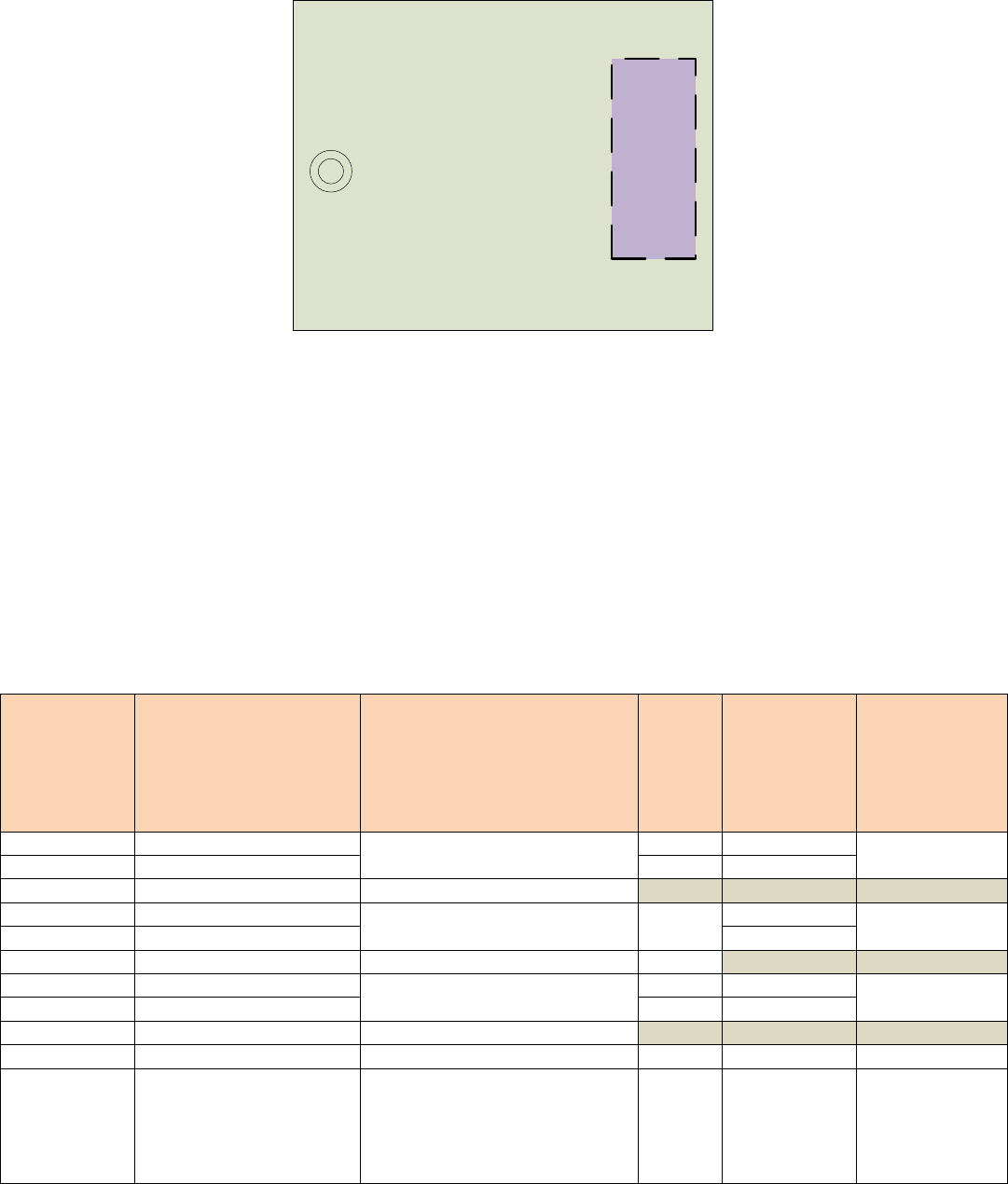
9.0 Interfaces
The figure below describes the connection and interface scheme for RA1202
Doc #: PD001743A01 Rev. B.0
Symbol Solutions, Inc. Page 15 of 22
Symbol Confidential Restricted
Radio Module
54-
pin
I/F
Antenna
U.FL
Connector
9.1 Interface and Connection Scheme
The RA1202 module power and data bus connector is as follows:
Radio module connector: Samtec ASP-176298-02
(8.7mm custom pin lengths of Samtec FTE-125-xx-G-DV-A-P-TR series)
Mating host connector: Samtec CLE-127-01-G-DV-A-K
Pin 1 of the radio board (part of the RA1202 radio module) has a square solder pad
and silkscreen.
Below pin-out is from the radio module’s reference point.
Pin Number
Signal Name
Description
Voltage
(V)
Direction (wrt
Radio
Module)
I - Input
O - Output
A – Analog
Pull Up or Pull
Down
1
RX_I_CAL_P
Receiver differential I signal from
receiver to modem
A
Test Signal – not
connected
3
RX_I_CAL_N
A
5
GND
Ground
7
TX_Q_CAL_P
Transmitter differential Q signal
from modem to transmitter.
1V p-p
A
Test Signal –
100Kohms
9
TX_Q_CAL_N
A
11
GND
Ground
13
TX_I_CAL_P
Transmitter differential I signal
from modem to transmitter.
A
Test Signal –
100Kohms
15
TX_I_CAL_N
A
17
GND
Ground
19
ABOUT_TO_TX
Indicator when about to transmit
3.0
O
None
21
BACKUP_ACTIVE
Set when radio should go into
emergency suspend mode (ex.
Battery removal on handheld
host).
3.3
I
PD (1M on Radio
Bd)
Requires
10kohm series
resistor on host.

Doc #: PD001743A01 Rev. B.0
Symbol Solutions, Inc. Page 16 of 22
Symbol Confidential Restricted
23
WAN_PWR_EN
Power enable for the radio
module from the hsot
3.3
I
PD (100K on
Radio Bd)
25
MCU_PWR_EN
Indicator when MCU power is
enabled
3.0
O
PD (10K on
Radio Board)
27
GND
Ground
29
MCU_UART2_RX
MCU serial port 2 (RS232 channel
to the host)
3.0
I
None
31
MCU_UART2_CTS
3.0
I
None
33
MCU_UART2_TX
3.0
O
None
35
MCU_UART2_RTS
3.0
O
None
37
JTAG_TRST_N/SPARE-2
None
39
GND
Ground
41
GND
Ground
43
GND
Ground
45
GND
Ground
47
VSYS
Radio Module Power Supply
3.2 to
4.2
Power
Tx current: 1.5A
@ 3.7V nominal
49
VSYS
51
VSYS
53
VSYS

Doc #: PD001743A01 Rev. B.0
Symbol Solutions, Inc. Page 17 of 22
Symbol Confidential Restricted
Pin Number
Signal Name
Description
Voltage
(V)
Direction (wrt
Radio
Module)
I - Input
O - Output
A – Analog
Pull Up or Pull
Down
2
RX_Q_CAL_N
Receiver differential Q signal
from receiver to modem
A
Test Signal – not
connected
4
RX_Q_CAL_P
O
6
GND
Ground
8
UPS_MODE
Indicator from Host to MCU -
radio to go into lower power
mode.
3.0
I
PD (100k on
Radio Board)
Future feature to
be implemented
10
NOT USED
12
NOT USED
14
GND
Ground
16
TX_ON (RF_PA_GATE_EN)
TX trigger signal from modem for
test equipment.
O
18
GND
Ground
20
SYMBOL_CLK
Symbol clock from modem
chipset
3.0
O
Test Signal – not
connected
22
GND
Ground
24
MCU_UART3_TX
MCU serial port 3 (MCU program
and debug)
3.0
O
26
MCU_UART3_RX
3.0
I
28
GND
Ground
30
MCU_BOOT1 **
MCU boot configuration
3.0
I
PD (100K on
Radio Board)
32
MCU_BOOT0 **
34
MCU_RST_N
MCU reset control signal
PD (100K on
Radio Board)
36
GND
38
DO NOT USE
40
JTAG_TCK
JTAG clock to the MCU.
3.0
I
PD (INT)
42
JTAG_TDI/SPI3_NCC
JTAG shared as SPI CS
3.0
O
None
44
JTAG_TDO/MCU_HRTBEAT
JTAG shared as debug signal
3.0
O
None
46
DO NOT USED
48
GND
Ground
50
JTAG_TMS/SPARE-1
JTAG shared as Spare GPIO
3.0
Undefined
None
52
MCU_SPARE_3
Spare GPIO
3.0
Undefined
None
** MCU_BOOT[1:0] = x0 MCU boot from MCU flash memory
MCU_BOOT[1:0] = 01 MCU boot from system memory
MCU_BOOT[1:0] = 11 MCU boot from Embedded SRAM
9.2 Antenna Connection
Connector: Hirose U.FL-R-SMT(10)
Antenna: 50 Ohm nominal impedance; external only, via interconnecting RF cable. Recommend
having a ferrite choke on RF antenna cable.

Doc #: PD001743A01 Rev. B.0
Symbol Solutions, Inc. Page 18 of 22
Symbol Confidential Restricted
10.0 Electrical Characteristics
10.1 Power Supply Requirements
Input Voltage Range
3.2 to 4.2 Vdc
Nominal Input Voltage
3.7Vdc
Current consumption at nominal input voltage
OFF
TBD mA
Idle
TBD mA
Receive
<200mA
Transmit
1.5A nominal at 1Watt output
10.2 Modes of Operation
RA1202 radio module shall support the following modes of operation:
OFF (Radio powered down, Power can remain present on Radio module interface)
Idle (Radio module MCU powered, but modem, transmitter, receiver and RF front
end off)
Receive
Transmit
11.0 Software Features and Functions
11.1 Radio Module Firmware
Radio module firmware running on the Radio module microcontroller (MCU) communicates
with the host, controls all aspects of the radio chipsets, RF front end and Tx/Rx switch.
11.2 Radio module serial number storage
During manufacturing, radio module serial number and part number are stored into the radio
module MCU write-once non-volatile flash memory. This allows host to query radio module part
number and serial number and therefore allow correlation of each radio module with the factory
test report.
11.3 Radio Type storage and security
RA1202 radio module has 2 hardware types. These 2 hardware types are configured during
manufacturing into 12 different radio types to meet country region approval requirements. Radio
type is factory set and stored in the radio MCU non-volatile memory.
Radio type is locked outside of manufacturing of the radio module. There are 3 levels of security
to ensure end users cannot modify the radio type outside of factory or authorized service depots:

Doc #: PD001743A01 Rev. B.0
Symbol Solutions, Inc. Page 19 of 22
Symbol Confidential Restricted
Locked and signed software does not allow access to commands to modify radio type.
Control panel in windows can only read the radio type.
Password protection. This is added security beyond the locked and signed software.
Specialized commands to change radio types, which are only available in
manufacturing and authorized service depots.
11.4 Radio Protocol
Drivers are available supporting the following features:
Compatible with Symbol’s NarrowBand Polling Protocol Cellular only. Non-cellular
modes not be supported.
Transparent roaming and power saving modes (terminals only). 9130/9140 2L
modulation base stations not be supported
RMAN API interface supported by the TekTerm application (terminals only)
Radio protocol diagnostic information (viewable via TekTerm for terminals)
11.5 Radio Calibration data
All calibration parameters are calibrated and tested during manufacturing then locked out from
end customers.
12.0 Host Software
12.1 Radio Tests
RTest command line utility allow developers and approval testers to perform the following radio
tests:
Channel (frequency) selection
Transmit long
Transmit test
Receive Test (BER)
12.2 Configuration and Tuning
RTest allows developer, manufacturing and approval tester to configure all necessary radio
settings such as data rate, modulation type and operating frequency.
End user shall not be able to modify any approval related parameters of the radio module.
This is done by 3 layers of protection described in section 11.3 of this document.
Doc #: PD001743A01 Rev. B.0
Symbol Solutions, Inc. Page 20 of 22
Symbol Confidential Restricted
12.3 Site Survey (terminals only)
A site survey application shall be developed for RA1202 that will perform in a similar manner to
the site survey application available on 7530 G2 and 8525/8530 G2 terminals. This is used by
system installers to determine the best location of base stations for new NarrowBand sites. It also
indicates the coverage level.
12.4 Software Update feature
Software is available to upgrade RA1202 firmware through UART host connection, for in-
system upgrade and depot upgrade.
As a backup in case of flash corruption and serial interface no longer operational it is possible to
update firmware through JTAG programming interface.
Only firmware which Regulatory Agency approved can be loaded on the radio module.
13.0 Mechanical & Ergonomic Specifications
13.1 General
Interface to Host: 54-pin Samtec ASP-176298-02
(8.7mm custom pin lengths of Samtec FTE-125-xx-G-DV-A-P-TR series)
Antenna Cable Interface: Hirose U.FL-R-SMT(10)
Weight: 37.1g
Dimensions: 64 (W) x 52.5 (L) x 17.1 (H) mm
13.2 Drop Rating
This is highly dependent upon host mounting system. For RA1202 Radio module integrated into
MSI XT15 handheld terminal the following drop specifications are met:
26 drops from 1.7m at room temperature to polished concrete
6 drops from 2.0 m at room temperature to polished concrete
6 drops from 1.7 m at -20C to polished concrete
6 drops from 1.7m at +50C to polished concrete
Doc #: PD001743A01 Rev. B.0
Symbol Solutions, Inc. Page 21 of 22
Symbol Confidential Restricted
13.3 Environmental Conditions
Storage temperature:
-35C to +85C
Operating temperature:
-30C to +80C
Humidity*:
5% to 95% (non-condensing)
Temperature shock*:
-30C to +50C (85% R.H.) as per MIL-STD-
810G; Method 503.5 Procedure I-C (Multi-
cycle shocks)
* There will be NO environmental protection on the RA1202 radio module, as it is designed to be
fully enclosed within a host unit.
13.4 Labeling Requirements
3 different labels must be in the following 3 locations:
External to RA1202 radio module
External to host unit
External to host unit shipping box
They must include all applicable notices as per regulatory requirements of section 5.0 adhering
to the minimum text and label sizes defined therein.
Identify Symbol Technologies Inc RA1202 radio module and part number specific to the radio
configuration.
Doc #: PD001743A01 Rev. B.0
Symbol Solutions, Inc. Page 22 of 22
Symbol Confidential Restricted
14.0 Appendices
Radio Performance Specifications
14.1 General
Frequency Range:
435-470 MHz [high band – FCC, IC, EU, & other]
403-435 MHz [low band – non-FCC, non-IC]
Frequency Control:
Synthesized
Channel Spacing:
12.5 kHz [FCC & others]
20 kHz [non-FCC]
25 kHz non Part 90
Mode of Operation:
Simplex or Half Duplex
Regulated Supply Voltage:
3.7VDC +/- 15%
Operating Temperature
Range:
-30C to +80C
Maximum Dimensions:
64 (W) x 52.5 (L) x 17.1 (H) mm
Weight:
37.1g
FCC Compliance:
Yes [high band only – 435-470 MHz]
No [low band]
14.2 Receiver
Bandwidth:
35 MHz [high band]
32 MHz [low band]
Frequency Stability:
+/- 1ppm [-30C to + 80C]
Digital Sensitivity
0.4uV at 1% BER [at 12.5 kHz channel spacing]
as per ETSI
EN300 113-1 v 1.7.1
RF Input Impedance
50 ohms
Selectivity
-61 dB [12.5 kHz channel spacing]
Spurious Rejection
88 dB
Intermodulation
-70dB
Conducted Spurious
85 dB
Receive Current Drain
200 mA
Receive Attach Time
< 3.5 msec
14.3 Transmitter
Bandwidth:
35 MHz [high band]
32 MHz [low band]
Frequency Stability:
+/- 1ppm [-30C to + 80C]
TCXO coupling
AC
RF Output Power
1W nominal
0.5W [available for non-FCC variant]
RF Output Impedance
50 ohms
Modulation Distortion
< 3%
Maximum Duty Cycle
30%, 60 seconds maximum continuous transmit time
Transmitter Attack Time
< 3.5 msec
Spurious & Harmonic FM
-79 dB
Transmit Current Drain
1.5A at 3.7 VDC nominal
14.4 Host Interface
Data Input Impedance
100 Kohms