Symbol Technologies RDRMP001 Frequency Hopping Spread Spectrum Transmitter User Manual Stationary Reader User s Manual
Symbol Technologies, Inc Frequency Hopping Spread Spectrum Transmitter Stationary Reader User s Manual
UserManual.wiki
>
Symbol Technologies
>
RDRMP001 User Manual
USers Manual
Navigation menu
Upload a User Manual
Namespaces
Wiki Guide
HTML
PDF
Info
Views
User Manual
Discussion / Help
Navigation
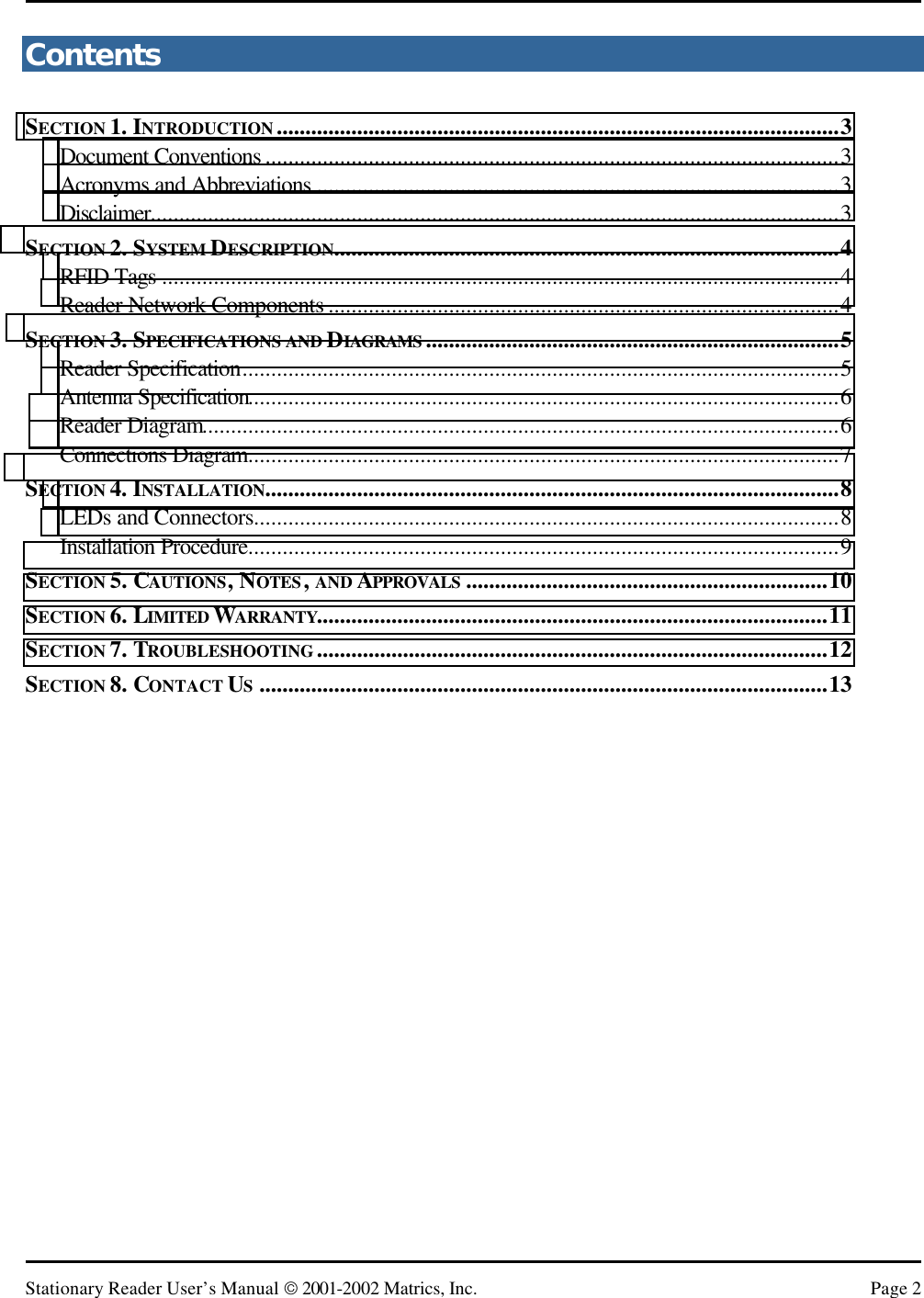
![Stationary Reader User’s Manual 2001-2002 Matrics, Inc. Page 4 Section 2. System Description Matrics develops and markets Radio Frequency Identification (RFID) that is effective and affordable by offering a combination of low cost, long read range, and a very high read rate unmatched by other RFID systems. A typical Matrics RFID system consists of three components: • Silicon-based RFID tags, • Reader network components (readers, antennas, cables, power supplies, CAT3 cable termination blocks, etc.), and • Your choice of Host/PC controller with system management software. RFID Tags Tags can be purchased as thin, flexible smart label inlays that can be incorporated into standard laminated paper or plastic to create inexpensive stick-on or embedded labels. Matrics smart labels can uniquely identify items up and down the supply chain, such as products in-process, pallets, boxes, trays, and totes. With an innovative approach that removes the circuit complexity from the integrated circuit (IC), Matrics UHF tags are simple and inexpensive to produce. The ultra lean chip design requires low power and consequently produces powerful read ranges. Each chip is extremely secure and tamper-proof, because the unique ID is programmed very early in the manufacturing process and cannot be altered. Reader Network Components The Matrics RFID Reader provides all of the RF and control functions required to power and communicate with Matrics passive RFID tags. It sends digital data to the tag (through one antenna at any given time) on a pulse width modulated On Off Keyed (OOK) transmitter signal, demodulates the identification signal received from the tag, and then sends the data to a host control device. The Matrics Reader system is structured to allow for flexibility in system configurations and in the arrangement of read points to optimize coverage at a low overall cost. In its maximum configuration, a single Reader can support a total of thirty-two (32) lower performance antennas [with eight (8) lower performance antennas attached to each of up to four (4) multiplexers attached to a Reader], or four (4) high performance antennas attached directly to a Reader. Any combination (up to the maximum) of high performance antennas (directly attached to the Reader) and lower performance antennas (attached to the Reader via multiplexers) can be implemented. The system also employs a unique, patented reader-driven interrogation protocol that allows up to one thousand (1,000) tags to be read each second. This powerful read rate supplies the muscle to overcome interference in noisy environments, and to guarantee acceptable read rates at each read point when large numbers of antennas are multiplexed together. Readers can be powered either locally or through the network cable in the event there is not a local power source near by, and to minimize overall network infrastructure costs.](https://usermanual.wiki/Symbol-Technologies/RDRMP001/User-Guide-227129-Page-4.png)
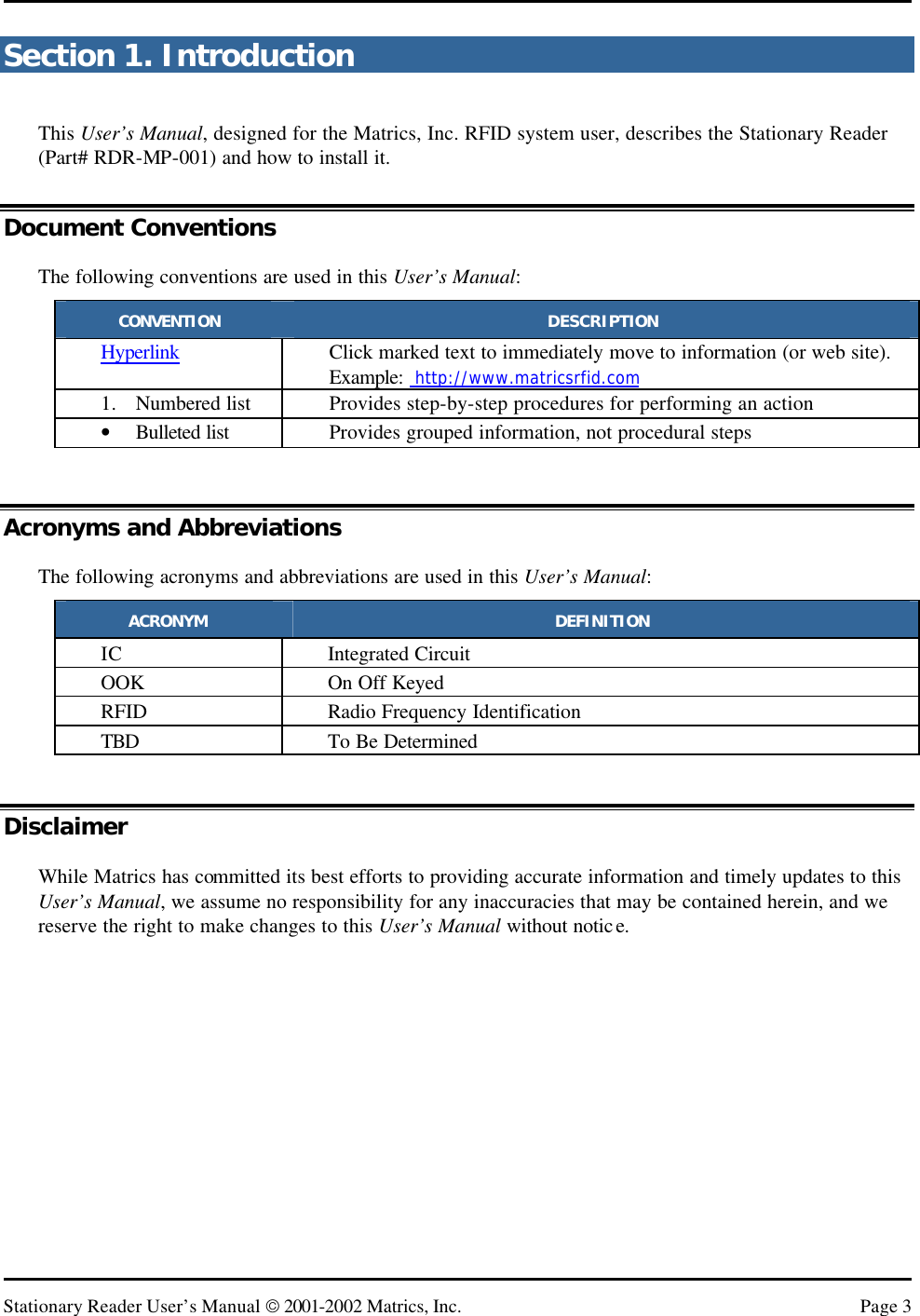
![Stationary Reader User’s Manual 2001-2002 Matrics, Inc. Page 7 Connections Diagram unspec.485convertorHost/PCStationary ReaderRDR-MP-001GeneralPurposeAntennaGeneralPurposeAntennaGeneralPurposeAntennaGeneralPurposeAntennaRG-142B(25' max.)123 4LocalPower(optional)WiringBlock5' PatchWiringBlockBelden #88757or equivalent(22 ga. CAT3)RJ45RJ45 CAT5std patch5' max.miniUHFWiringBlockBus PowerWiringBlockWiringBlock Reader 20 (max. for bus power)Reader 32 (max. for local power)WiringBlockStd 485 BusTerminatorRx ± ] 120ΩTx ± ] 120Ω250'max.buspowered-or-500'max.locallypoweredFunctional System ConnectionsMatrics, Inc. 11/26/01Reader 1Std 485 BusTerminatorRx ± ] 120ΩTx ± ] 120Ω](https://usermanual.wiki/Symbol-Technologies/RDRMP001/User-Guide-227129-Page-7.png)