Symbol Technologies RDRMP001 Frequency Hopping Spread Spectrum Transmitter User Manual Stationary Reader User s Manual
Symbol Technologies, Inc Frequency Hopping Spread Spectrum Transmitter Stationary Reader User s Manual
USers Manual

Stationary Reader
(Part# RDR-MP-001)
User’s Manual
Published: January 30, 2002
Document Control Number: MNI01H001
Matrics, Inc.
8850 Stanford Boulevard
Suite 3000
Columbia, MD 21045
Tel: 410.872.0300
Fax: 410.872.0700
http://www.matricsrfid.com

Stationary Reader User’s Manual 2001-2002 Matrics, Inc. Page 2
Contents
SECTION 1. INTRODUCTION ..................................................................................................3
Document Conventions ....................................................................................................3
Acronyms and Abbreviations ...........................................................................................3
Disclaimer........................................................................................................................3
SECTION 2. SYSTEM DESCRIPTION........................................................................................4
RFID Tags ......................................................................................................................4
Reader Network Components .........................................................................................4
SECTION 3. SPECIFICATIONS AND DIAGRAMS ........................................................................5
Reader Specification........................................................................................................5
Antenna Specification.......................................................................................................6
Reader Diagram...............................................................................................................6
Connections Diagram.......................................................................................................7
SECTION 4. INSTALLATION....................................................................................................8
LEDs and Connectors......................................................................................................8
Installation Procedure.......................................................................................................9
SECTION 5. CAUTIONS, NOTES , AND APPROVALS ...............................................................10
SECTION 6. LIMITED WARRANTY.........................................................................................11
SECTION 7. TROUBLESHOOTING .........................................................................................12
SECTION 8. CONTACT US...................................................................................................13
Stationary Reader User’s Manual 2001-2002 Matrics, Inc. Page 3
Section 1. Introduction
This User’s Manual, designed for the Matrics, Inc. RFID system user, describes the Stationary Reader
(Part# RDR-MP-001) and how to install it.
Document Conventions
The following conventions are used in this User’s Manual:
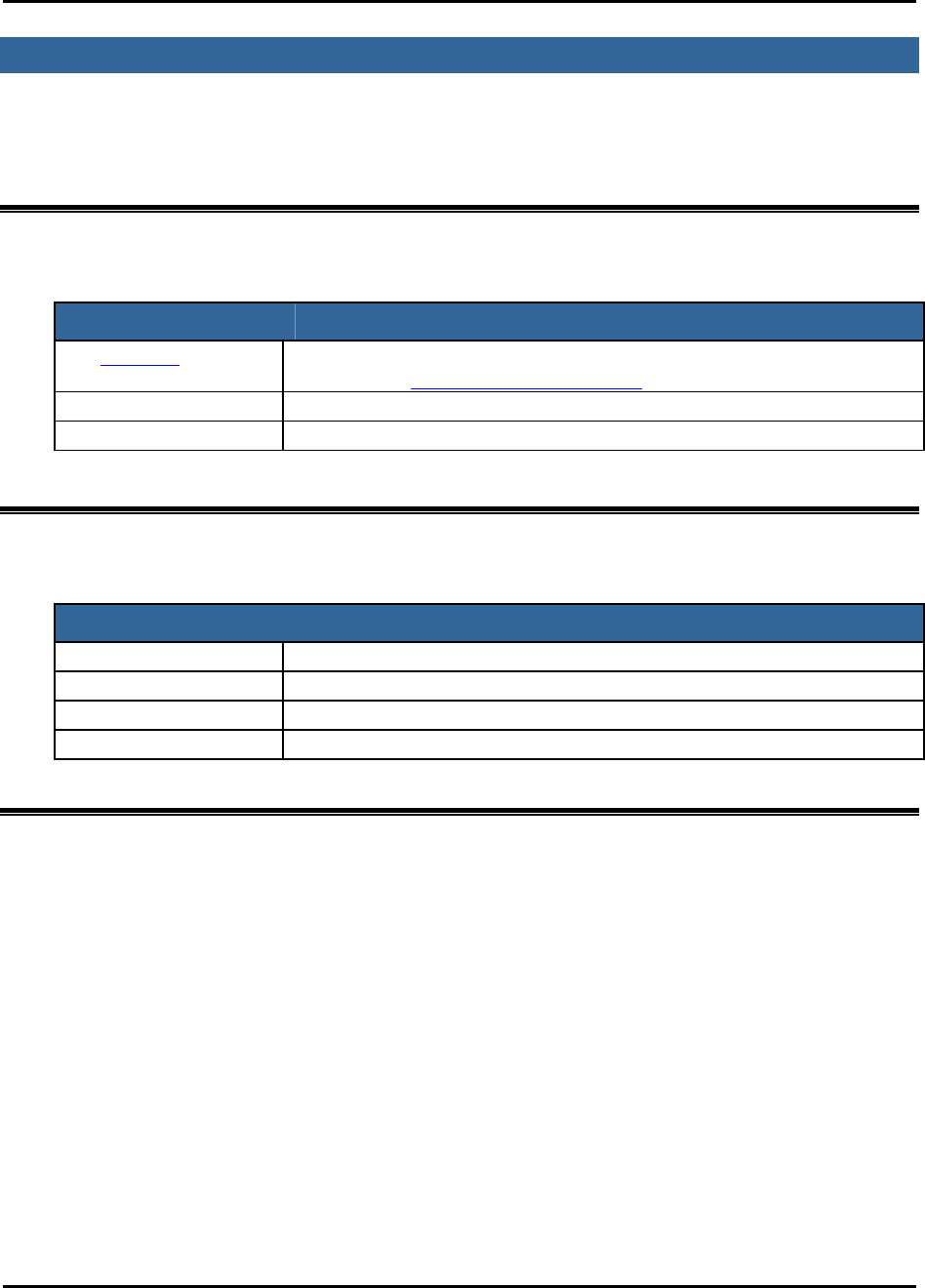
CONVENTION DESCRIPTION
Hyperlink Click marked text to immediately move to information (or web site).
Example: http://www.matricsrfid.com
1. Numbered list Provides step-by-step procedures for performing an action
• Bulleted list Provides grouped information, not procedural steps
Acronyms and Abbreviations
The following acronyms and abbreviations are used in this User’s Manual:
ACRONYM DEFINITION
IC Integrated Circuit
OOK On Off Keyed
RFID Radio Frequency Identification
TBD To Be Determined
Disclaimer
While Matrics has committed its best efforts to providing accurate information and timely updates to this
User’s Manual, we assume no responsibility for any inaccuracies that may be contained herein, and we
reserve the right to make changes to this User’s Manual without notice.

Stationary Reader User’s Manual 2001-2002 Matrics, Inc. Page 4
Section 2. System Description
Matrics develops and markets Radio Frequency Identification (RFID) that is effective and affordable by
offering a combination of low cost, long read range, and a very high read rate unmatched by other RFID
systems. A typical Matrics RFID system consists of three components:
• Silicon-based RFID tags,
• Reader network components (readers, antennas, cables, power supplies, CAT3 cable termination
blocks, etc.), and
• Your choice of Host/PC controller with system management software.
RFID Tags
Tags can be purchased as thin, flexible smart label inlays that can be incorporated into standard laminated
paper or plastic to create inexpensive stick-on or embedded labels. Matrics smart labels can uniquely
identify items up and down the supply chain, such as products in-process, pallets, boxes, trays, and
totes.
With an innovative approach that removes the circuit complexity from the integrated circuit (IC), Matrics
UHF tags are simple and inexpensive to produce. The ultra lean chip design requires low power and
consequently produces powerful read ranges. Each chip is extremely secure and tamper-proof, because
the unique ID is programmed very early in the manufacturing process and cannot be altered.
Reader Network Components
The Matrics RFID Reader provides all of the RF and control functions required to power and
communicate with Matrics passive RFID tags. It sends digital data to the tag (through one antenna at any
given time) on a pulse width modulated On Off Keyed (OOK) transmitter signal, demodulates the
identification signal received from the tag, and then sends the data to a host control device.
The Matrics Reader system is structured to allow for flexibility in system configurations and in the
arrangement of read points to optimize coverage at a low overall cost. In its maximum configuration, a
single Reader can support a total of thirty-two (32) lower performance antennas [with eight (8) lower
performance antennas attached to each of up to four (4) multiplexers attached to a Reader], or four (4)
high performance antennas attached directly to a Reader. Any combination (up to the maximum) of high
performance antennas (directly attached to the Reader) and lower performance antennas (attached to the
Reader via multiplexers) can be implemented.
The system also employs a unique, patented reader-driven interrogation protocol that allows up to one
thousand (1,000) tags to be read each second. This powerful read rate supplies the muscle to overcome
interference in noisy environments, and to guarantee acceptable read rates at each read point when large
numbers of antennas are multiplexed together.
Readers can be powered either locally or through the network cable in the event there is not a local power
source near by, and to minimize overall network infrastructure costs.

Stationary Reader User’s Manual 2001-2002 Matrics, Inc. Page 5
Section 3. Specifications and Diagrams
Reader Specification
The following table provides the specifications for the Reader:
CHARACTERISTIC DESCRIPTION
Name/Part Number Stationary Reader, RDR-MP-001
Operating Frequency UHF band, 902-928 MHz, frequency hopping
System Architecture Point-to-multipoint reader network
Dimensions 12.5” wide (includes mounting plate) x 8.75” high
(includes connectors) x 1.5” deep
Simultaneous Reading Capability Up to 1000 tags per second
Operating Temperature Operational: 0° to +50° C
Storage: -20° to +70° C
Communications Interface RS485, 232400 bps, no flow control, no parity, 8
data bits, 1 stop bit
Inputs/Outputs 4 dual coax antenna mini-UHF connectors, 1 RJ45
host comm., 1 2.5 mm power, 1 RJ14 multiplexer
Power Supply +24 VDC, 1.2A (unregulated)
Power Consumption 30 watts operational, 1 watt standby
RJ45 Pin Assignments
(host communications)
Pin 1: Tx+ Data
Pin 2: Tx- Data
Pin 3: Power Return and Ground
Pin 4: +24VDC
Pin 5: +24VDC
Pin 6: Power Return and Ground
Pin 7: Rx- Data
Pin 8: Rx+ Data
Multiplexer connection
Pin 1: Clock+
Pin 2: Clock-
Pin 3: +12V
Pin 4: +12V
Pin 5: Tx- Data
Pin 6: Tx+ Data
Stationary Reader User’s Manual 2001-2002 Matrics, Inc. Page 6
Antenna Specification
The following table provides the specifications for the antenna:
CHARACTERISTIC AT 915 MHZ
Name/Part Number General Purpose Antenna, RAN-GP-001
Input Standing Wave Ratio (VSWR) 1.25
Isolation -db -37
3db Beam Width 60°
Gain in dbd/linear 6
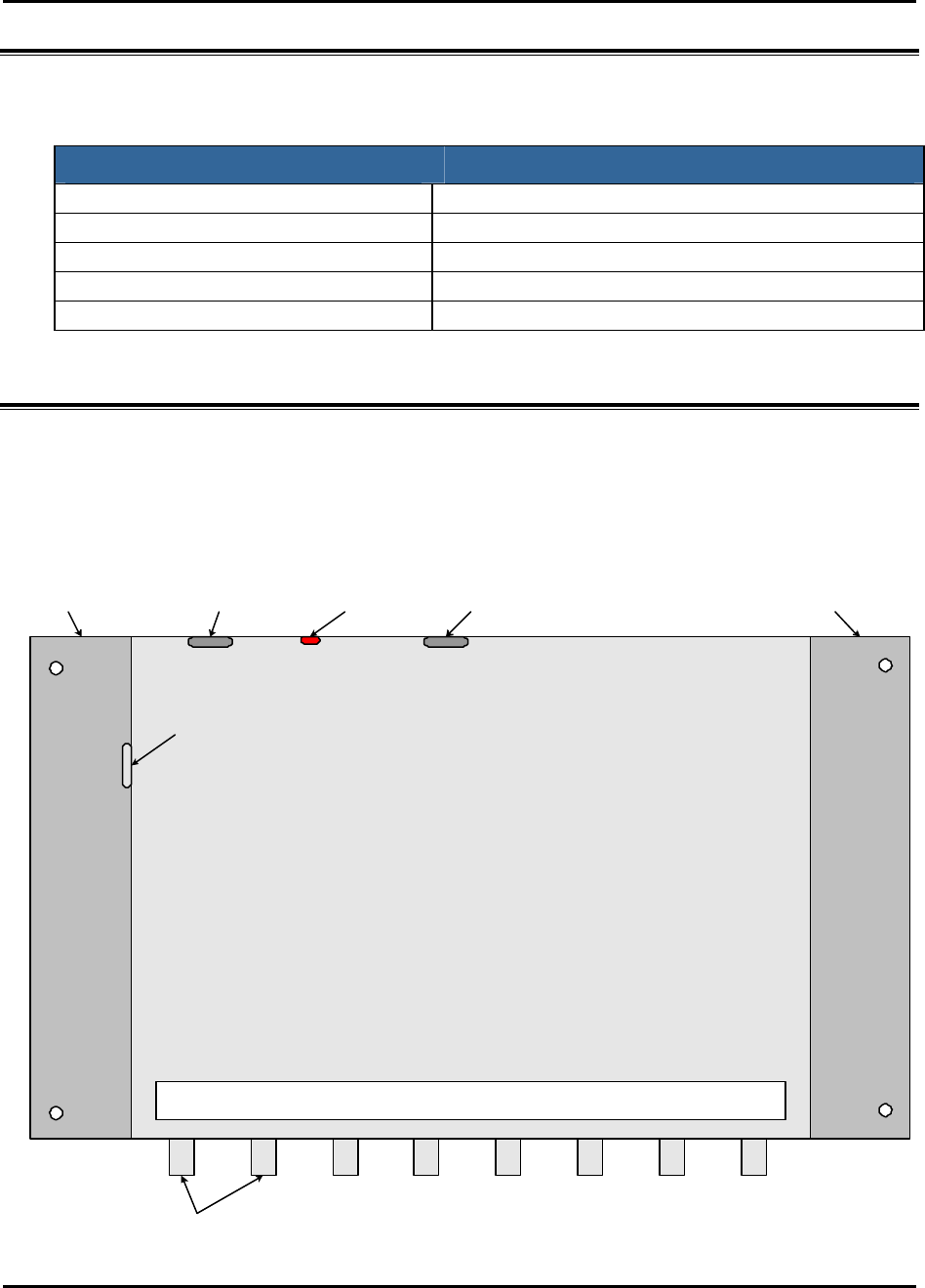
Reader Diagram
Stationary Reader
RDR-MP-001
Multiplexer
Connector
Stationary Reader
RDR-MP-001
Matrics, Inc. 11/26/01
Tx 4Tx3Tx2Tx1Rx4Rx3Rx2Rx1
485 / Bus Power
Connector Power/Activity
LED
+24VDC
1.2A Connector
(Unit Power)
Mounting
Plate
Mounting
Plate
12.5" wide (includes mounting plate)
x 8.75" high (includes connectors)
Antenna Connectors
Stationary Reader User’s Manual 2001-2002 Matrics, Inc. Page 7
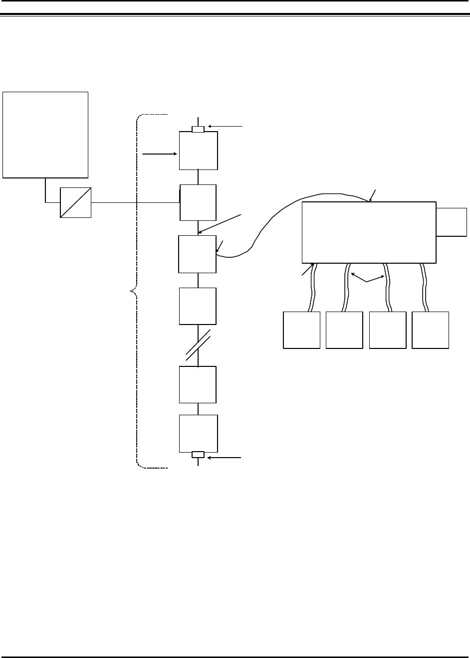
Connections Diagram
unspec.
485
convertor
Host/PC
Stationary Reader
RDR-MP-001
General
Purpose
Antenna
General
Purpose
Antenna
General
Purpose
Antenna
General
Purpose
Antenna
RG-142B
(25' max.)
123 4
Local
Power
(optional)
Wiring
Block
5' Patch
Wiring
Block
Belden #88757
or equivalent
(22 ga. CAT3)
RJ45
RJ45 CAT5
std patch
5' max.
mini
UHF
Wiring
Block
Bus Power
Wiring
Block
Wiring
Block Reader 20 (max. for bus power)
Reader 32 (max. for local power)
Wiring
Block
Std 485 Bus
Terminator
Rx ± ] 120Ω
Tx ± ] 120Ω
250'
max.
bus
powered
-or-
500'
max.
locally
powered
Functional System Connections
Matrics, Inc. 11/26/01
Reader 1
Std 485 Bus
Terminator
Rx ± ] 120Ω
Tx ± ] 120Ω

Stationary Reader User’s Manual 2001-2002 Matrics, Inc. Page 8
Section 4. Installation
Check that you have everything you need before you proceed with the installation. In addition to this
User’s Manual, you should have received the following items in your package:
• One Matrics Stationary Reader (Part# RDR-MP-001)
• Wall mount Power Supply (optional)
• Mounting equipment
• CAT5 jumper cable
• CAT3 cable termination block (“wiring block”)
• Utility software.
Contact Matrics (refer to the “Contact Us” section in this User’s Manual for more information) if any of
the above-listed items arrived damaged or are missing from your package.
LEDs and Connectors
The following table describes the Reader’s hardware. It lists the front and back panel’s connectors, etc.,
and specifies the electrical inputs and outputs:
ITEM DESCRIPTION
Power/Activity LED LED is red when the Reader is powered On and receiving power. The
light blinks when commands are correctly received from the Host/PC.
RS485 / Bus Power
Connector Connect to Host/PC and bus power.
RJ14 Connector For future use.
+24VDC 1.2A
Connector (Unit
Power)
The power supply should be plugged into a wall outlet and into the DC
power connector.
Mini-UHF Antenna
Connectors Connect to external antennas.

Stationary Reader User’s Manual 2001-2002 Matrics, Inc. Page 9
Installation Procedure
The Reader installation consists of the following steps:
1. Mount your antenna(s) in a location chosen for optimum operation. Make sure that you follow the
FCC guidelines for antenna placement. The antenna should be at least two (2) meters from any
unsuspecting personnel.
2. Mount the Reader on a wall near your antenna(s) locations.
CAUTION: The Reader must reside indoors, in operating range, and out of
direct sunlight, high moisture, or extreme temperatures.
3. Cable to connect the external antenna(s). Maximum cable length is 25’.
4. Cable to connect the Reader to the Host/PC.
5. Power On the Reader.
6. Configure the Reader using the Utility software provided in your package. Follow the prompts to
change your Readers’ factory-assigned xFF address to a unique address for communicating with
your Host/PC.

Stationary Reader User’s Manual 2001-2002 Matrics, Inc. Page 10
Section 5. Cautions, Notes, and Approvals
Matrics products are approved (or approval pending) by the appropriate regulatory agencies:
• Federal Communications Commission (FCC), Part 15
• Underwriter Laboratory, UL 294
Note: This equipment has been tested and found to comply with the limits for a Class A digital device,
pursuant to Part 15 of the FCC Rules. These limits are designed to provide reasonable protection against
harmful interference when the equipment is operated in a commercial environment. This equipment
generates, uses, and can radiate radio frequency energy and, if not installed and used in accordance with
the User’s Manual, may cause harmful interference to radio communications. Operation of this
equipment in a residential area is likely to cause harmful interference in which case the user will be
required to correct the interference at his or her own expense.
CAUTION: Changes or modifications not expressly approved by the party
responsible for compliance could void the user’s authority to operate the
equipment.
Information to the User: This device complies with Part 15 of the FCC Rules. Operation is subject to
the following two conditions: (1) This device may not cause harmful interference, and (2) This device
must accept any interference received, including interference that may cause undesired operation.
WARNING: This device must be installed in a location that is not
accessible to the general public. Install the device so that the antenna is at
least two (2) meters from unsuspecting personnel. Failure to install this
device as described will result in a failure to comply with FCC rules for RF
exposure and is discouraged.
Disclaimer: Operation of any radio transmitting equipment, including this product, may interfere with the
functionality of inadequately protected medical devices. Consult a physician or the manufacturer of the
medical device if you have any questions. Other electronic equipment may also be subject to interference.

Stationary Reader User’s Manual 2001-2002 Matrics, Inc. Page 11
Section 6. Limited Warranty
Matrics warrants its products to the original purchaser to be free of defects in workmanship and material
for a period of ninety (90) days from date of receipt. Matrics’ sole and complete responsibility under this
warranty is expressly limited to repair or replacement of the defective product.
Replacement products may be new or reconditioned. All products that are replaced shall become the
property of Matrics The warranty for replacement products is the same as the equivalent newly
purchased product.
Any tampering or modification to the product, or subjecting of product to abnormal electrical,
mechanical, or environmental abuse will void this product warranty.

Stationary Reader User’s Manual 2001-2002 Matrics, Inc. Page 12
Section 7. Troubleshooting
In the event you encounter a problem with your Reader, refer to the following table for possible solutions:
PROBLEM POSSIBLE CAUSE SOLUTION
The Power/Activity
LED doesn’t light.
The AC outlet may not
be working or may be
controlled by a wall
switch.
Plug a different electrical appliance into
the outlet and turn it on. If the
appliance doesn’t work, plug the
Reader into a different outlet.
The Power/Activity
LED is on but
doesn’t blink.
The Reader isn’t
communicating with
the Host/PC,
-or-
The Host/PC isn’t
communicating with
the Reader.
Check that your Host/PC’s port
settings are configured properly.
Make sure that you used the Utility
software to change the Reader’s
factory-assigned xFF address to a
unique address for communicating with
your Host/PC.
Check to ensure proper network
cabling (including terminators at both
ends.)
Verify communications at a fixed
230,400 rate.

Stationary Reader User’s Manual 2001-2002 Matrics, Inc. Page 13
Section 8. Contact Us
For general and technical assistance, contact Matrics at:
Tel: 410.872.0300
Monday-Friday 8:30 a.m. – 5:00 p.m. EST
Fax: 410.872.0700
http://www.matricsrfid.com/
Matrics, Inc.
8850 Stanford Boulevard
Suite 3000
Columbia, MD 21045
USA