Symbol Technologies Spectrum24 Ap 4131 Users Manual Tril_AP_3 0_
AP-4131 to the manual 53b7ae35-3e56-4661-96ba-3fbdd6c87e8e
2015-02-02
: Symbol-Technologies Symbol-Technologies-Spectrum24-Ap-4131-Users-Manual-449024 symbol-technologies-spectrum24-ap-4131-users-manual-449024 symbol-technologies pdf
Open the PDF directly: View PDF ![]() .
.
Page Count: 250 [warning: Documents this large are best viewed by clicking the View PDF Link!]
- Spectrum24 AP-4131 Access Point
- Chapter 1 Introduction
- 1.1 Access Point (AP)
- 1.2 Radio Basics
- 1.3 Access Point Functional Theory
- 1.3.1 MAC Layer Bridging
- 1.3.2 Auto Fallback to Wireless Mode
- 1.3.3 DHCP Support
- 1.3.4 Media Types
- 1.3.5 Direct-Sequence Spread Spectrum
- 1.3.6 MU Association Process
- 1.3.7 Mobile IP
- 1.3.8 Supporting CAM and PSP Stations
- 1.3.9 Data Encryption
- 1.3.10 Kerberos Authentication
- 1.3.11 KSS Open Enrollment
- 1.3.12 KSS Databases
- 1.3.13 Roaming and Authentication
- 1.3.14 Mixed Mode Security
- 1.3.15 Web Management Support
- 1.3.16 Management Options
- Chapter 2 Configuring the AP
- 2.1 Gaining Access to the UI
- 2.2 Navigating the UI
- 2.3 Access Point Installation
- 2.4 Configuring System Parameters
- 2.5 Configuring Radio Parameters
- 2.6 Encryption Configuration and Key Maintenance
- 2.7 Configuring the SNMP Agent
- 2.8 ACL and Address Filtering
- 2.9 Configuring Address Filtering
- 2.10 Configuring Type Filtering
- 2.11 Clearing MUs from the AP
- 2.12 Manually Updating the AP Configuration
- 2.13 Setting Logging Options
- 2.14 Updating AP Firmware
- 2.15 Auto Upgrade all APs Through Messaging
- 2.16 Performing Pings
- 2.17 Mobile IP Using MD5 Authentication
- 2.18 Saving the Configuration
- 2.19 Resetting the AP
- 2.20 Restoring the Factory Configuration
- 2.21 Configuring Network Time
- Chapter 3 Monitoring Statistics
- Chapter 4 Hardware Installation
- Appendix A Specifications
- Appendix B Supported Modems
- Appendix C Customer Support
- Appendix D Country Identification Codes
- Appendix E Installing and Configuring Kerberos Setup Service
- Index

www.symbol.com
Spectrum24
AP-4131 Access Point
Product Reference Guide
72E-56316-01
Revision A
February 2002

ii AP-4131 Access Point Product Reference Guide
Copyright
Copyright © 2002 by Symbol Technologies, Inc. All rights reserved.
No part of this publication may be modified or adapted in any way, for any purposes without permission in writing from Symbol. The material in this manual
is subject to change without notice.
Symbol reserves the right to make changes to any product to improve reliability, function, or design.
No license is granted, either expressly or by implication, estoppel, or otherwise under any Symbol Technologies, Inc., intellectual property rights. An implied
license only exists for equipment, circuits, and subsystems contained in Symbol products.
Symbol, the Symbol logo and Spectrum24 are registered trademarks of Symbol Technologies, Inc.
Other product names mentioned in this manual may be trademarks or registered trademarks of their respective companies and are hereby acknowledged.
IBM is a registered trademark of International Business Machine Corporation.
Microsoft, Windows, and Windows NT are registered trademarks of Microsoft Corporation.
Novell and LAN Workplace are registered trademarks of Novell Inc.
Toshiba is a trademark of Toshiba Corporation.
Patents
This product is covered by one or more of the following U.S. and foreign Patents:
4,496,831; 4,593,186; 4,603,262; 4,607,156; 4,652,750; 4,673,805; 4,736,095; 4,758,717; 4,760,248; 4,806,742; 4,816,660; 4,845,350;
4,896,026; 4,897,532; 4,923,281; 4,933,538; 4,992,717; 5,015,833; 5,017,765; 5,021,641; 5,029,183; 5,047,617; 5,103,461; 5,113,445;
5,130,520; 5,140,144; 5,142,550; 5,149,950; 5,157,687; 5,168,148; 5,168,149; 5,180,904; 5,216,232; 5,229,591; 5,230,088; 5,235,167;
5,243,655; 5,247,162; 5,250,791; 5,250,792; 5,260,553; 5,262,627; 5,262,628; 5,266,787; 5,278,398; 5,280,162; 5,280,163; 5,280,164;
5,280,498; 5,304,786; 5,304,788; 5,306,900; 5,321,246; 5,324,924; 5,337,361; 5,367,151; 5,373,148; 5,378,882; 5,396,053; 5,396,055;
5,399,846; 5,408,081; 5,410,139; 5,410,140; 5,412,198; 5,418,812; 5,420,411; 5,436,440; 5,444,231; 5,449,891; 5,449,893; 5,468,949;
5,471,042; 5,478,998; 5,479,000; 5,479,002; 5,479,441; 5,504,322; 5,519,577; 5,528,621; 5,532,469; 5,543,610; 5,545,889; 5,552,592;
5,557,093; 5,578,810; 5,581,070; 5,589,679; 5,589,680; 5,608,202; 5,612,531; 5,619,028; 5,627,359; 5,637,852; 5,664,229; 5,668,803;
5,675,139; 5,693,929; 5,698,835; 5,705,800; 5,714,746; 5,723,851; 5,734,152; 5,734,153; 5,742,043; 5,745,794; 5,754,587; 5,762,516;
5,763,863; 5,767,500; 5,789,728; 5,789,731; 5,808,287; 5,811,785; 5,811,787; 5,815,811; 5,821,519; 5,821,520; 5,823,812; 5,828,050;
5,850,078; 5,861,615; 5,874,720; 5,875,415; 5,900,617; 5,902,989; 5,907,146; 5,912,450; 5,914,478; 5,917,173; 5,920,059; 5,923,025;
5,929,420; 5,945,658; 5,945,659; 5,946,194; 5,959,285; 6,002,918; 6,021,947; 6,036,098; 6,047,892; 6,050,491; 6,053,413; 6,056,200;
6,065,678; 6,067,297; 6,068,190; 6,082,621; 6,084,528; 6,088,482; 6,092,725; 6,101,483; 6,102,293; 6,104,620; 6,114,712; 6,115,678;
6,119,944; 6,123,265; 6,131,814; 6,138,180; 6,142,379; 6,172,478; 6,176,428; 6,178,426; 6,186,400; 6,188,681; 6,209,788; 6,216,951;
6,220,514; 6,243,447; 6,244,513; 6,247,647; 6,250,551; D305,885; D341,584; D344,501; D359,483; D362,453; D363,700; D363,918;
D370,478; D383,124; D391,250; D405,077; D406,581; D414,171; D414,172; D418,500; D419,548; D423,468; D424,035; D430,158;
D430,159; D431,562; D436,104.
Invention No. 55,358; 62,539; 69,060; 69,187 (Taiwan); No. 1,601,796; 1,907,875; 1,955,269 (Japan); European Patent 367,299; 414,281;
367,300; 367,298; UK 2,072,832; France 81/03938; Italy 1,138,713
Symbol Technologies, Inc.
One Symbol Plaza
Holtsville, N.Y. 11742-1300
Telephone:(800)SCAN234, (516)738-2400, TLX:6711519
www.symbol.com

AP-4131 Access Point Product Reference Guide iii
About This Document
Reference Documents
This reference guide refers to the following documents:
Conventions
Keystrokes are indicated as follows:
Typeface conventions used include.
Part Number Document Title
72E-51753-01 Wireless LAN Adapter 4100 Series PC Card & PCI Adapter Product
Reference Guide
72E-51754-01 Spectrum24 DS Plus Pack Users Guide
72E-51755-01 Spectrum24 Site Survey System Administrators Guide
ENTER identifies a key.
FUNC, CTRL, C identifies a key sequence. Press and release each key in turn.
Press A+B press the indicated keys simultaneously.
Hold A+B press and hold the indicated keys while performing or waiting for another
function. Used in combination with another keystroke.
<angles> indicates mandatory parameters in syntax.
[brackets] for command line, indicates available parameters; in configuration files,
brackets act as separators for options.
GUI Screen text indicates the name of a control in a GUI-based application.
Italics indicates the first use of a term, book title, variable or menu title.
Screen indicates monitor screen dialog. Also indicates user input. A screen is
the hardware device on which data appears. A display is data arranged
on a screen.
Terminal indicates text shown on a radio terminal screen.
URL indicates Uniform Resource Locator.

iv AP-4131 Access Point Product Reference Guide
This document uses the following for certain conditions or information:
Indicates tips or special requirements.
Indicates conditions that can cause equipment damage or data loss.
Indicates a potentially dangerous condition or procedure that only Symbol-
trained personnel should attempt to correct or perform.

Contents
AP-4131 Access Point Product Reference Guide v
Chapter 1 Introduction .......................................................................................1
1.1 Access Point (AP)...........................................................................1
1.2 Radio Basics .................................................................................3
1.2.1 S24 Network Topology........................................................3
1.2.2 Cellular Coverage ..............................................................8
1.2.3 Site Topography ...............................................................11
1.3 Access Point Functional Theory.....................................................12
1.3.1 MAC Layer Bridging..........................................................13
1.3.2 Auto Fallback to Wireless Mode .........................................14
1.3.3 DHCP Support..................................................................15
1.3.4 Media Types.....................................................................16
1.3.5 Direct-Sequence Spread Spectrum......................................18
1.3.6 MU Association Process .....................................................19
1.3.7 Mobile IP .........................................................................21
1.3.8 Supporting CAM and PSP Stations ......................................24
1.3.9 Data Encryption................................................................25
1.3.10 Kerberos Authentication...................................................26
1.3.11 KSS Open Enrollment......................................................31
1.3.12 KSS Databases ...............................................................32
1.3.13 Roaming and Authentication ............................................32
1.3.14 Mixed Mode Security .......................................................33
1.3.15 Web Management Support..............................................33
1.3.16 Management Options .....................................................34
Chapter 2 Configuring the AP.........................................................................37
2.1 Gaining Access to the UI .............................................................37
2.1.1 Using Telnet .....................................................................37
2.1.2 Using a Direct Serial Connection........................................39
2.1.3 Using a Dial-Up Connection..............................................40

vi AP-4131 Access Point Product Reference Guide
2.1.4 Using a Web Browser........................................................41
2.2 Navigating the UI .......................................................................48
2.2.1 Entering Admin Mode .......................................................50
2.2.2 Changing the Access to the UI ...........................................51
2.2.3 Configuring for Dial-Up to the UI.......................................53
2.2.4 Navigating the UI Using a Web Browser .............................54
2.3 Access Point Installation...............................................................54
2.4 Configuring System Parameters....................................................59
2.4.1 Encryption Administration ..................................................66
2.4.2 System Password Administration.........................................69
2.5 Configuring Radio Parameters .....................................................71
2.5.1 Wireless AP Operation Parameters .....................................80
2.5.2 Enhanced Packet Prioritization (EPP)....................................85
2.5.3 Enhanced Interference Avoidance Properties (EIAP) ..............86
2.6 Encryption Configuration and Key Maintenance.............................88
2.6.1 40-Bit WEP Encryption.......................................................90
2.6.2 128-Bit WEP Encryption.....................................................92
2.6.3 Manual Kerberos Authentication Configuration ...................94
2.6.4 Configuring EAP-TLS Support.............................................97
2.6.5 Configuring Mixed Mode Security.....................................100
2.7 Configuring the SNMP Agent .....................................................102
2.7.1 Configuring SNMPv3 Security ..........................................108
2.8 ACL and Address Filtering .........................................................111
2.8.1 Configuring the ACL .......................................................113
2.8.2 Range of MUs ................................................................113
2.8.3 Adding Allowed MUs ......................................................115
2.8.4 Removing Allowed MUs...................................................115
2.8.5 ACL Options ..................................................................116
2.8.6 Removing All Allowed MUs ..............................................116
2.8.7 Load ACL from MU List ...................................................116
2.8.8 Load ACL from File .........................................................117

AP-4131 Access Point Product Reference Guide vii
2.9 Configuring Address Filtering.....................................................118
2.9.1 Adding Disallowed MUs ..................................................119
2.9.2 Removing Disallowed MUs ..............................................119
2.10 Configuring Type Filtering .......................................................120
2.10.1 Adding Filter Types .......................................................120
2.10.2 Removing Filter Types....................................................120
2.10.3 Controlling Type Filters..................................................120
2.11 Clearing MUs from the AP .......................................................121
2.12 Manually Updating the AP Configuration ..................................121
2.12.1 Updating Using TFTP ....................................................129
2.12.2 Updating Using Xmodem ..............................................132
2.13 Setting Logging Options ..........................................................137
2.14 Updating AP Firmware ............................................................139
2.14.1 Update Using TFTP .......................................................139
2.14.2 Updating Using Xmodem ..............................................143
2.15 Auto Upgrade all APs Through Messaging ................................148
2.16 Performing Pings ....................................................................152
2.17 Mobile IP Using MD5 Authentication.........................................155
2.18 Saving the Configuration .........................................................156
2.19 Resetting the AP ......................................................................157
2.20 Restoring the Factory Configuration..........................................157
2.21 Configuring Network Time.......................................................158
Chapter 3 Monitoring Statistics.....................................................................159
3.1 System Summary ......................................................................159
3.2 Interface Statistics......................................................................163
3.3 Forwarding Counts ...................................................................164
3.4 Mobile Units.............................................................................165
3.5 Mobile IP..................................................................................170
3.6 Known APs ...............................................................................171
3.7 Ethernet Statistics ......................................................................174
3.8 Radio Statistics..........................................................................176

viii AP-4131 Access Point Product Reference Guide
3.9 Miscellaneous Statistics..............................................................182
3.9.1 Analyzing Channel Use ...................................................184
3.9.2 Analyzing Retries ............................................................185
3.10 Event History ..........................................................................186
3.11 Clearing Statistics....................................................................187
Chapter 4 Hardware Installation..................................................................189
4.1 Precautions ..............................................................................189
4.2 Package Contents .....................................................................189
4.3 Requirements ...........................................................................190
4.3.1 Network Connection .......................................................190
4.3.2 10/100Base-T UTP .........................................................190
4.3.3 Single Cell .....................................................................191
4.4 Placing the AP ..........................................................................191
4.5 Power Options..........................................................................192
4.6 Mounting the AP .......................................................................193
4.7 Connecting the Power Adapter...................................................193
4.8 BIAS-T Low Power Distribution System.........................................194
4.9 LED Indicators ..........................................................................198
4.9.1 WLAP mode LED display..................................................199
4.10 Troubleshooting......................................................................201
4.10.1 Ensure wired network is operating ..................................201
4.11 Setting Up MUs.......................................................................202
Appendix A Specifications .............................................................................. A-1
A.1 Physical Characteristics ............................................................. A-1
A.2 Radio Characteristics................................................................. A-2
A.3 Network Characteristics............................................................ A-3
Appendix B Supported Modems.................................................................... B-1
Appendix C Customer Support .....................................................................C-1
Appendix D Country Identification Codes...................................................D-1

AP-4131 Access Point Product Reference Guide ix
Appendix E Installing and Configuring Kerberos Setup Service ............. E-1
E.1 Creating a Windows 2000 Environment for the KSS ..................... E-1
E.2 Installing the KSS in a Windows 2000 Environment ...................... E-2
E.3 Preparing the KSS for Access Point Validation .............................. E-5
E.4 Manually Creating an Access Point Setup Account...................... E-12
E.5 Implementing Kerberos without the KSS .................................... E-14
Index............................................................................................................. Index-1

x AP-4131 Access Point Product Reference Guide

AP-4131 Access Point Product Reference Guide 1
Chapter 1 Introduction
Spectrum24 is a spread spectrum cellular network that operates between
2.4 and 2.5 GHz (gigahertz). This technology provides a high-capacity
network using multiple access points within any environment.
The Symbol AP-4131Access Point (AP) is a Spectrum24 direct-sequence (DS)
product. Spectrum24 DS products use direct-sequence technology to provide
a high-capacity, high-data-rate wireless network.
Spectrum24 DS infrastructure products include:
• bridging architecture to provide communication between radio and
wired multiple network segments
• a design based on the IEEE 802.11 standard
• an 11 Mbps data rate for fast operation
• seamless roaming for mobile users with devices such as laptops, wireless
PCs, scanning terminals and other computers with PCMCIA slots.
1.1 Access Point (AP)
The Access Point (AP) provides a bridge between Ethernet wired LANs and
wireless networks. It provides connectivity between Ethernet wired networks
and radio-equipped mobile units (MUs). MUs include the full line of Symbol
Spectrum24 terminals, PC Cards, bar-code scanners and other devices.
This guide provides configuration and setup information for the AP-4131
model access point. Refer to the rear of the access point for product model
information.
The AP provides an 11 Mbps data transfer rate on the radio network.
It monitors Ethernet traffic and forwards appropriate Ethernet messages to
MUs over the Spectrum24 network. It also monitors MU radio traffic and
forwards MU packets to the Ethernet LAN.

Introduction
2 AP-4131 Access Point Product Reference Guide
The AP meets the following:
• the regulatory requirements for Europe and many other areas of
the world
• FCC part 15, class A with no external shielding
• FCC part 15 class B, ETS 300-339 compliance, including CE mark.
The AP has the following features:
• built-in diagnostics including a power-up self-check
• built-in dual antenna assembly with optional diversity
• wireless MAC interface
• field upgradable Firmware
• 10/100Base-T Ethernet port interface with full-speed filtering
• power supply IEC connector and a country-specific AC power cable
• data encryption
• supports multiple MIBs
• SNMP support
• support for roaming across routers
•DHCP support
•BOOTP
•DNS support
• Web browser user interface support
•short RF preamble
• wireless AP mode.
When properly configured, an MU communicating with an AP appears on
the network as a peer to other network devices. The AP receives data from its
wired interfaces and forwards the data to the proper interface.
The AP has connections for the wired network and power supply. The AP
attaches to a wall or ceiling depending on installation-site requirements.

Introduction
AP-4131 Access Point Product Reference Guide 3
1.2 Radio Basics
Spectrum24 devices use electromagnetic waves to transmit and receive
electric signals without wires. Users communicate with the network by
establishing radio links between MUs and APs.
Spectrum24 products use DSSS (direct sequence spread spectrum) to transmit
digital data from one device to another. Using FM, a radio signal begins with
a carrier signal that provides the base or center frequency. The digital data
signal is encoded onto the carriers using a DSSS “chipping algorithm”. The
radio signal propagates into the air as electromagnetic waves. A receiving
antenna in the path of the waves absorbs the waves as electrical signals. The
receiving device demodulates the signal by reapplying the direct sequence
chipping code. This demodulation results in the original digital data.
Spectrum24 uses the environment (the air and certain objects) as the
transmission medium. Spectrum24 radio devices transmit in the
2.4 to 2.5-GHz frequency range, a license-free range throughout most of
the world. The actual range is country-dependent.
Spectrum24 devices, like other Ethernet devices, have unique, hardware-
encoded Media Access Control (MAC) or IEEE addresses. MAC addresses
determine the device sending or receiving data. A MAC address is a 48-bit
number written as six hexadecimal bytes separated by colons.
For example:
00:A0:F8:24:9A:C8
1.2.1 S24 Network Topology
The variations possible in Spectrum24 network topologies depend on the
following factors:
• the AP function in the network
• the data transfer rate
• the wireless AP (WLAP) interface.
Introduction
4 AP-4131 Access Point Product Reference Guide
A WLAP communicates only with its root AP through the wireless interface.
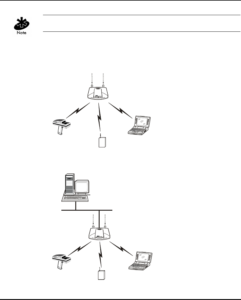
Select from the following topologies:
• A single AP used without the wired network provides a single-cell wireless
network for peer-to-peer MUs.
• A single AP can bridge the Ethernet and radio networks.
Introduction
AP-4131 Access Point Product Reference Guide 5
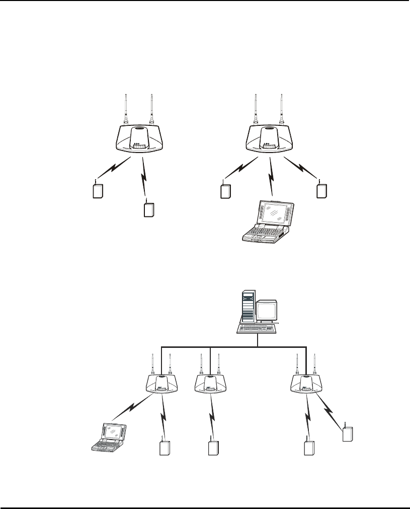
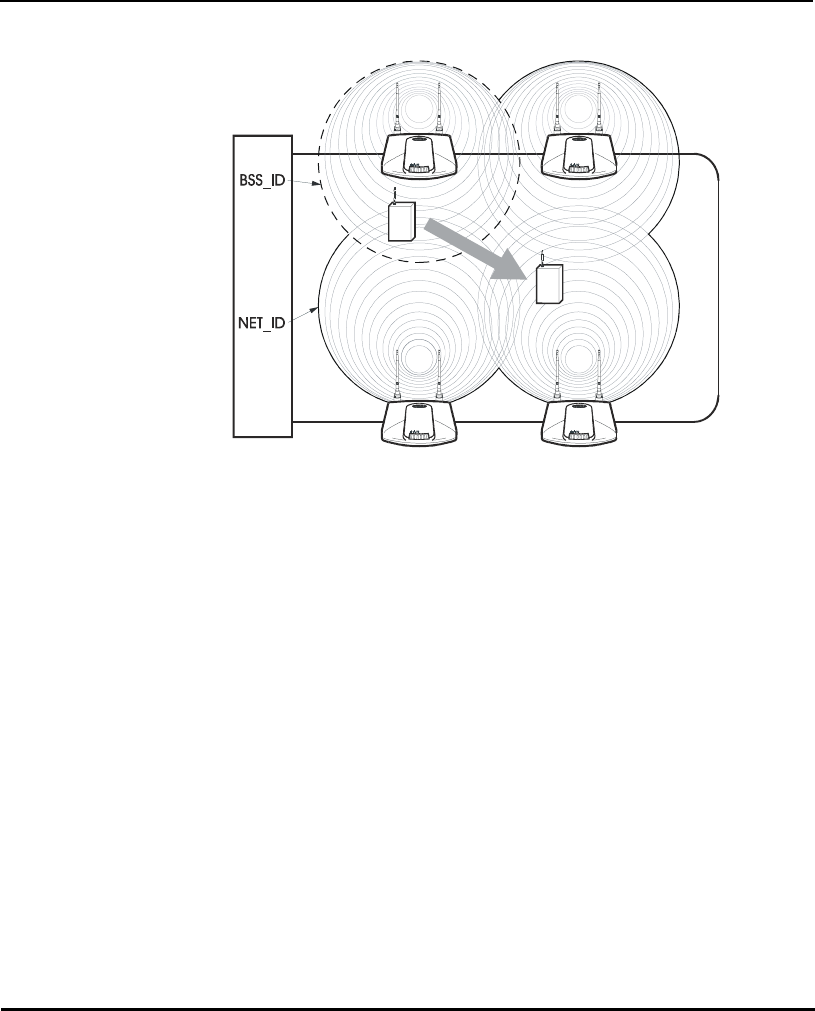
• Multiple APs can coexist as separate, individual networks at the same site
without interference using different Net_IDs. The Net_ID (ESS) can be
thought of as a Wireless LAN Network Identifier. These separate Wireless
LANs may be configured to use different channel assignments to avoid
RF interference.
• Multiple APs wired together provide a network with better coverage area
and performance when using the same Net_IDs.
Introduction
6 AP-4131 Access Point Product Reference Guide
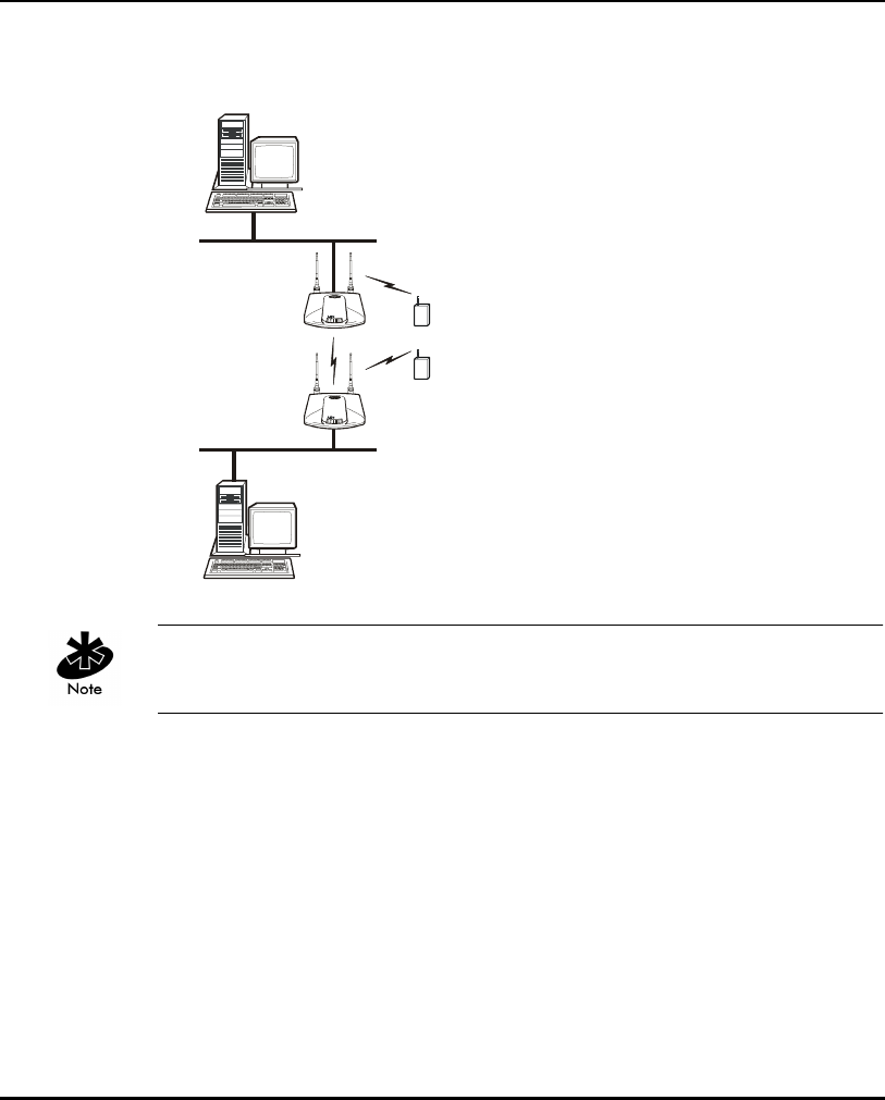
In WLAP mode, a wireless AP-to-AP connection functions:
• as a bridge to connect two Ethernet networks
Kerberos, EAP-TLS and the Mobile IP feature are not available when the
access point is operating in WLAP mode.
Introduction
AP-4131 Access Point Product Reference Guide 7
In WLAP mode, APs and MUs are required to have the same Preamble
settings to interoperate. Additionally, the root AP is required to be running
before the “leaf” or WLAP connection is established.
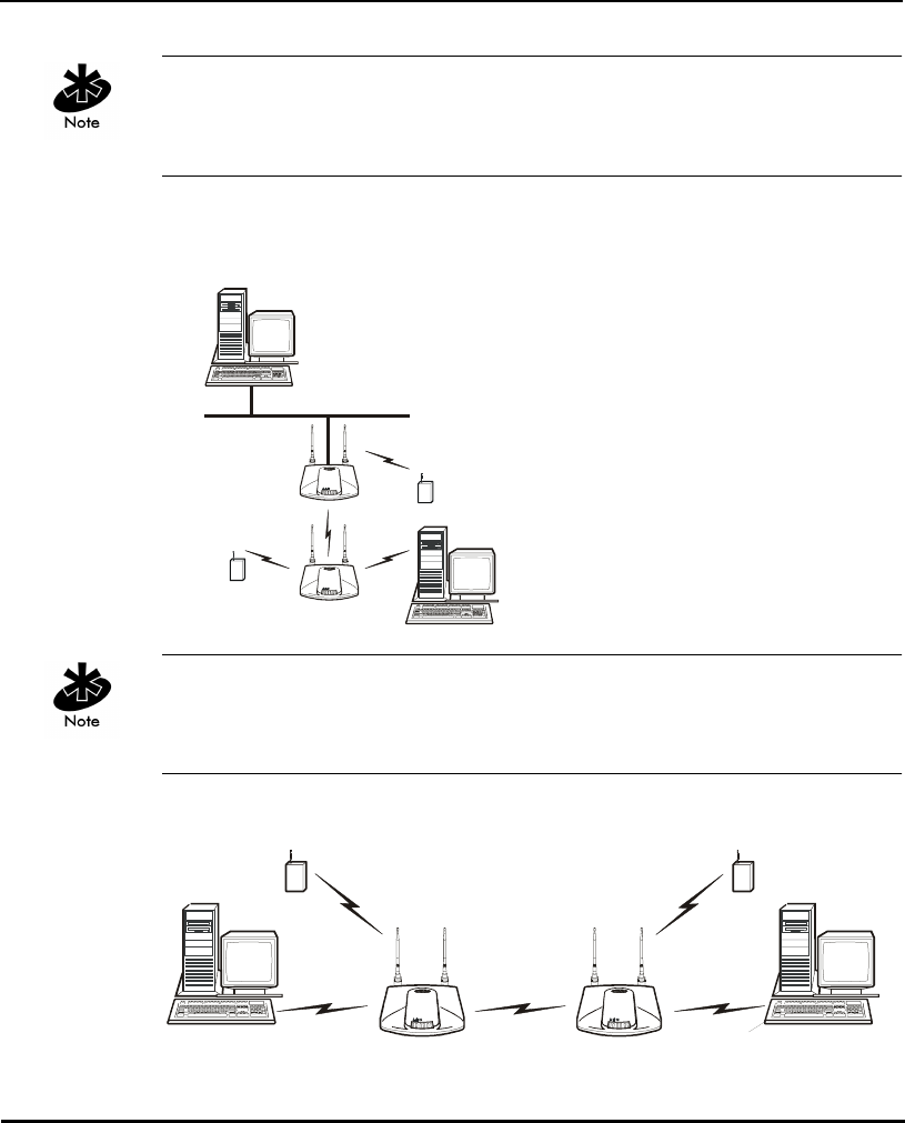
• as a repeater to extend coverage area without additional
network cabling.
When using a wireless AP-to-AP connection, use the optimal antenna
configuration for the site. For example, use a directional antenna when
establishing a dedicated wireless bridge or repeater.
• Each wireless AP can have connections with up to four other wireless APs.

Introduction
8 AP-4131 Access Point Product Reference Guide
Using more than two WLAPs to establish a connection slows network
performance for all topologies. To increase WLAP performance, disable
WNMP Functions and AP-AP State Xchg parameters under the Set System
Configuration screen.
To set up an AP for wireless operation automatically, select the Enabled
option for the WLAP Mode parameter. To set these values, see section 2.5:
”Configuring Radio Parameters” on page 71.
The WLAP initialization process length depends on the time specified in
the WLAP Forward Delay field. See section 2.5: ”Configuring Radio
Parameters” on page 71.
1.2.2 Cellular Coverage
The AP establishes an average communication range with MUs called a
Basic Service Set (BSS) or cell. When in a particular cell the MU associates
and communicates with the AP of that cell. Each cell has a Basic Service Set
Identifier (BSS_ID). In IEEE 802.11, the AP MAC (Media Access Control)
address represents the BSS_ID. The MU recognizes the AP it associates with
using the BSS_ID.
Spectrum24 devices, like other network devices, have unique, hardware-
encoded MAC or IEEE addresses. MAC addresses determine the device
sending or receiving the data. A MAC address is a 48-bit number written as
six hexadecimal bytes separated by colons. For example:
00:A0:F8:24:9A:C8
An MU recognizes the access point it associates with using the BSS_ID.
Adding access points to a single LAN establishes more cells to extend the
range of the network. Configuring the same ESS_ID (Extended Service Set
Identifier) on all access points make them part of the same Wireless LAN.
Introduction
AP-4131 Access Point Product Reference Guide 9
APs with the same Net_ID (ESS) define a coverage area. The MU searches for
APs with a matching Net_ID (ESS) and synchronizes with an AP to establish
communications. This allows MUs within the coverage area to move
about or roam. As the MU roams from cell to cell, it switches APs. The switch
occurs when the MU analyzes the reception quality at a location and decides
which AP to communicate with based on the best signal strength and lowest
MU load distribution.
If the MU does not find an AP with a workable signal, it performs a scan to
find any AP. As MUs switch APs, the AP updates the association table.
The user can configure the Net_ID (ESS). A valid Net_ID (ESS) is an
alphanumeric, case-sensitive identifier up to 32 characters. Ensure all nodes
within one LAN use the same Net_ID (ESS) to communicate on the same
LAN. Multiple wireless LANs can coexist in a single environment by assigning
different Net_IDs (ESS) for APs.
Introduction
10 AP-4131 Access Point Product Reference Guide
The Root AP and Association Process
By default, APs with WLAP Mode enabled and within range of each other
automatically associate and configure wireless operation parameters at
power up. This association process determines the wireless connection
viability and establishes the Root AP and subsequently designated WLAPs.
APs communicating wirelessly with one another require the same: Net_ID
(ESS), Encryption mode, Data Rate and Short RF Preamble settings.
The root AP maintains the wireless connection among WLAPs by sending out
beacons, sending and receiving configuration BPDU (Bridge Protocol Data
Unit) packets between each designated WLAP. The WLAP with the lowest
WLAP ID becomes the Root AP. A concatenation of the WLAP Priority value
and the MAC address becomes the WLAP ID. All WLAPs associated with the a
Root AP use the Root AP channel, DTIM (Delivery Traffic Indication Message)
and TIM (Traffic Indication Map) interval.
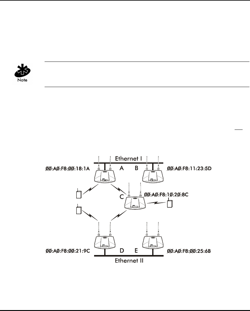
In this configuration, the WLAP Priority value is the default 8000 Hex. On
concatenating this value to the MAC addresses of the APs, AP A on Ethernet I
has the lowest WLAP ID with 800000A0F800181A, making it the Root AP.
AP C uses the AP A channel, DTIM and TIM interval.

Introduction
AP-4131 Access Point Product Reference Guide 11
If AP D on Ethernet II has data for a device on Ethernet I, it requires a bridge
or a repeater. In this configuration, AP C functions as a repeater. To ensure
transmission to devices on Ethernet I, AP D has to use the AP A channel,
DTIM and TIM interval.
The AP with lowest WLAP priority value is the Root AP. To manually designate
AP B as the Root AP, assign it a WLAP Priority value less than 8000 Hex. See
section 2.5: ”Configuring Radio Parameters” on page 71.
IEEE 802.1d Spanning Tree Support
This protocol creates a loop-free topography with exactly ONE path between
every device and LAN. This is the shortest path from the Root AP to each
WLAP and LAN. If the connection between a WLAP and LAN fails, a new
route is calculated and added to the tree. All packet forwarding follows the
spanning tree path determined. APs in a network have to choose one AP as
the Root AP.
1.2.3 Site Topography
For optimal performance, locate MUs and APs away from transformers,
heavy-duty motors, fluorescent lights, microwave ovens, refrigerators and
other industrial equipment.
Signal loss can occur when metal, concrete, walls or floors block
transmission. Locate APs in open areas or add APs as needed to
improve coverage.
Site Surveys
A site survey analyzes the installation environment and provides users with
recommendations for equipment and its placement. The optimum placement
of 11 Mbps access points differs for 1 or 2 Mbps access points, because the
locations and number of access points required are different.

Introduction
12 AP-4131 Access Point Product Reference Guide
Symbol recommends conducting a new site survey and developing a new
coverage area floor plan when switching from 1 or 2 Mbps frequency-
hopping access points to 11 Mbps direct-sequence access points.
1.3 Access Point Functional Theory
To improve AP management and performance, users need to understand
basic AP functionality and configuration options. The AP includes features
for different interface connections and network management.
The AP provides MAC layer bridging between its interfaces. The AP monitors
traffic from its interfaces and, based on frame address, forwards the frames
to the proper destination. The AP tracks the frames sources and destinations
to provide intelligent bridging as MUs roam or network topologies change.
The AP also handles broadcast and multicast messages and responds to MU
association requests.
Introduction
AP-4131 Access Point Product Reference Guide 13
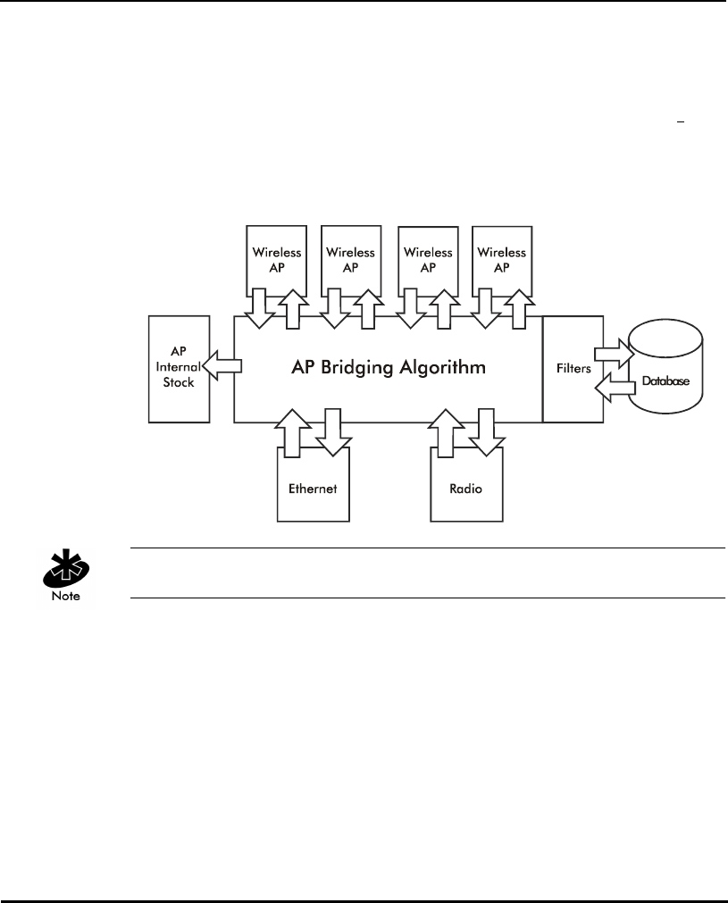
1.3.1 MAC Layer Bridging
The AP listens to all packets on all interfaces and builds an address database
using the unique IEEE 48-bit address (MAC address). An address in the
database includes the interface media that the device uses to associates with
the AP. The AP uses the database to forward packets from one interface to
another. The bridge forwards packets addressed to unknown systems to the
Default Interface (Ethernet).
The AP internal stack interface handles all messages directed to the AP.
Each AP stores information on destinations and their interfaces to facilitate
forwarding. When a user sends an ARP (Address Resolution Protocol) request
packet, the AP forwards it over all enabled interfaces (Ethernet, radio and
WLAP) except over the interface the ARP request packet was received.
On receiving the ARP response packet, the AP database keeps a record
of the destination address along with the receiving interface. With this
information, the AP forwards any directed packet to the correct destination.
The AP forwards packets for unknown destinations to the Ethernet interface.

Introduction
14 AP-4131 Access Point Product Reference Guide
Transmitted ARP request packets echo back to other MUs.
The AP removes from its database the destination or interface information
that is not used for a specified time. The AP refreshes its database when it
transmits or receives data from these destinations and interfaces.
Filtering and Access Control
The AP provides facilities to limit the MUs that associate with it and the data
packets that can forward through it. Filters provide network security and
improve performance by eliminating broadcast/multicast packets from the
radio network.
The ACL (Access Control List) contains MAC addresses for MUs
allowed to associate with the AP. This provides security by preventing
unauthorized access.
The AP uses a disallowed address list of destinations. This feature prevents
the AP from communicating with specified destinations. This can include
network devices that do not require communication with the AP or its MUs.
Depending on the setting, the AP can keep a list of frame types that it
forwards or discards. The Type Filtering option prevents specific frames
(indicated by the 16-bit DIX Ethernet Type field) from being processed by
the AP. These include certain broadcast frames from devices that consume
bandwidth but are unnecessary to the wireless LAN. Filtering out
frames can also improve performance.
1.3.2 Auto Fallback to Wireless Mode
The AP supports an Auto Fallback to wireless mode when the hardware
Ethernet connection fails or becomes broken. The Auto Fallback function
operates only with an AP in WLAP mode and connected to the Ethernet
network. The AP resets itself and during initialization attempts to associate
with any other WLAP in the network.

Introduction
AP-4131 Access Point Product Reference Guide 15
See section 2.4 “Configuring System Parameters” on page 59 and section
2.5.1: ”Wireless AP Operation Parameters” on page 80.
To enable this feature, set the WLAP Mode to Link Required.
1.3.3 DHCP Support
The AP can use Dynamic Host Configuration Protocol (DHCP) to obtain a
leased IP address and configuration information from a remote server. DHCP
is based on BOOTP protocol and can coexist or interoperate with BOOTP.
Configure the AP to send out a DHCP request searching for a DHCP/BOOTP
server to acquire Kerberos security information, HTML, firmware or network
configuration files when a boot (an AP boot) takes place. Because BOOTP
and DHCP interoperate, whichever responds first becomes the server that
allocates information.
The AP can be set to only accept replies from DHCP or BOOTP servers or
both (this is the default setting). Setting DHCP to disabled disables BOOTP
and DHCP (configure network settings manually). If running both DHCP and
BOOTP, do not select BOOTP Only. BOOTP should only be used when the
server is running BOOTP exclusively. See section 2.3 “Access Point
Installation” on page 54.
The DHCP client automatically sends a DHCP request at an interval specified
by the DHCP server to renew the IP address lease as long as the AP is
running (This parameter is programmed at the DHCP server). For example:
Windows NT servers typically are set for 3 days.

Introduction
16 AP-4131 Access Point Product Reference Guide
Program the DHCP or BOOTP server to transfer these files (Kerberos security
information, HTML, firmware or network configuration files) with these DHCP
options for the specific file or information to download:
When the AP receives a network configuration change or is not able to renew
the IP address lease the AP sends out an SNMP trap if SNMP is configured.
1.3.4 Media Types
The AP supports bridging between Ethernet and radio media.
The Ethernet interface fully complies with Ethernet Rev. 2 and IEEE 802.3
specifications. The 4131 AP supports a 10/100Base-T wired connection. The
data transfer rate is 11 Mbps.
The radio interface conforms to IEEE 802.11 specifications. The interface
operates at 11 Mbps using direct-sequence radio technology. The AP
supports multiple-cell operations with fast roaming between cells. With the
direct-sequence system, each cell operates independently. Each cell provides
an 11 Mbps bandwidth. Adding cells to the network provides increased
coverage area and total system capacity. The AP supports MUs operating in
Power Save Polling (PSP) mode or Continuously Aware Mode (CAM) without
user intervention.
DHCP Option Value
Firmware and HTML file 67 (filenames are separated by a space)
ESSID 128
Configuration filename 129
ACL filename 130
Kerberos enable/disable flag 131(set to 0 for disable or 1 for enable on
the DHCP server)
KDC name 132
KSS name 133
KSS port number 134

Introduction
AP-4131 Access Point Product Reference Guide 17
The DB-9, 9-pin, RS-232 serial port provides a UI (User Interface)
connection. The UI provides basic management tools for the AP. The serial
link supports short haul (direct serial) or long haul (telephone-line)
connections. The AP is a DTE (Data Terminal Equipment) device with male
pin connectors for the RS-232 port. Connecting the AP to a PC requires a
null modem cable.
Introduction
18 AP-4131 Access Point Product Reference Guide
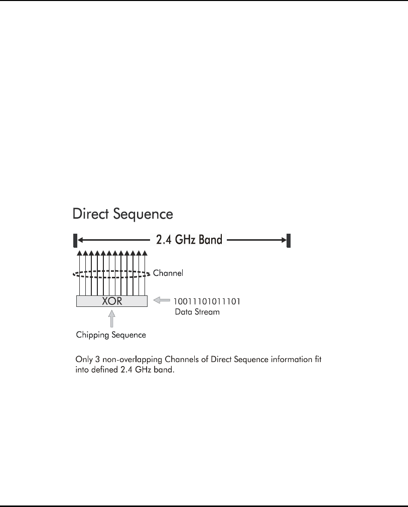
1.3.5 Direct-Sequence Spread Spectrum
Spread spectrum (broadband) uses a narrowband signal to spread the
transmission over a segment of the radio frequency band or spectrum.
Direct-sequence is a spread spectrum technique where the transmitted signal
is spread over a particular frequency range. The Spectrum24 AP-4131access
point uses Direct-Sequence Spread Spectrum (DSSS) for radio
communication.
Direct-sequence systems communicate by continuously transmitting a
redundant pattern of bits called a chipping sequence. Each bit of transmitted
data is mapped into chips by the access point and rearranged into a
pseudorandom spreading code to form the chipping sequence. The chipping
sequence is combined with a transmitted data stream to produce the AP
output signal.

Introduction
AP-4131 Access Point Product Reference Guide 19
Mobile Units receiving a direct-sequence transmission use the spreading
code to map the chips within the chipping sequence back into bits to recreate
the original data transmitted by the access point. Intercepting and decoding
a direct-sequence transmission requires a predefined algorithm to associate
the spreading code used by the transmitting access point to the receiving MU.
This algorithm is established by IEEE 802.11b specifications. The bit
redundancy within the chipping sequence enables the receiving MU to
recreate the original data pattern, even if bits in the chipping sequence are
corrupted by interference.
The ratio of chips per bit is called the spreading ratio. A high spreading ratio
increases the resistance of the signal to interference. A low spreading ratio
increases the bandwidth available to the user. The access point uses a
constant chip rate of 11Mchips/s for all data rates, but uses different
modulation schemes to encode more bits per chip at the higher data rates.
The access point is capable of an 11 Mbps data transmission rate, but the
coverage area is less than a 1 or 2 Mbps access point since coverage area
decreases as bandwidth increases.
1.3.6 MU Association Process
APs recognize MUs as they associate with the AP. The AP keeps a list of the
MUs it services. MUs associate with an AP based on the following conditions:
• the signal strength between the AP and MU
• MUs currently associated with the AP
• the MUs encryption and authentication capabilities and the type enabled
• the MUs supported data rates (1 Mbps, 2 Mbps, 5.5 Mbps or 11 Mbps).
MUs perform preemptive roaming by intermittently scanning for APs and
associating with the best available AP. Before roaming and associating with
APs, MUs perform full or partial scans to collect AP statistics and determine
the direct-sequence channel used by the AP.

Introduction
20 AP-4131 Access Point Product Reference Guide
Scanning is a periodic process where the MU sends out probe messages on
all channels defined by the country code. The statistics enable an MU to
reassociate by synchronizing its channel to the AP. The MU continues
communicating with that AP until it needs to switch cells or roam.
MUs perform full scans at start-up. In a full scan, an MU uses a sequential
set of channels as the scan range. For each channel in range, the MU tests
for CCA (Clear Channel Assessment). When a transmission-free channel
becomes available, the MU broadcasts a probe with the Net_ID (ESS) and
the broadcast BSS_ID. An AP-directed probe response generates an
MU ACK (Mobile Unit Acknowledgment) and the addition of the AP to the AP
table with a proximity classification. An unsuccessful AP packet transmission
generates another MU probe on the same channel. If the MU fails to receive
a response within the time limit, it repeats the probe on the next channel in
the sequence. This process continues through all channels in the range.
MUs perform partial scans at programmed intervals, when missing expected
beacons or after excessive transmission retries. In a partial scan, the MU
scans APs classified as proximate on the AP table. For each channel,
the MU tests for CCA. The MU broadcasts a probe with the Net_ID (ESS)
and broadcast BSS_ID when the channel is transmission-free. It sends an
ACK to a directed probe response from the AP and updates the AP table.
An unsuccessful AP packet transmission causes the MU to broadcast another
probe on the same channel. The MU classifies an AP as out-of-range in the
AP table if it fails to receive a probe response within the time limits. This
process continues through all APs classified as proximate on the AP table.

Introduction
AP-4131 Access Point Product Reference Guide 21
An MU can roam within a coverage area by switching APs. Roaming
occurs when:
• an unassociated MU attempts to associate or reassociate with an
available AP
• the supported rate changes or the MU finds a better transmit rate with
another AP
•the RSSI (received signal strength indicator) of a potential AP exceeds the
current AP
• the ratio of good-transmitted packets to attempted-transmitted packets
falls below a threshold.
An MU selects the best available AP and adjusts itself to the AP direct-
sequence channel to begin association. Once associated, the AP begins
forwarding any frames it receives addressed to the MU. Each frame contains
fields for the current direct-sequence channel. The MU uses these fields to
resynchronize to the AP.
The scanning and association process continues for active MUs. This process
allows the MUs to find new APs and discard out-of-range or deactivated APs.
By testing the airwaves, the MUs can choose the best network connection
available.
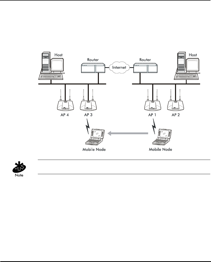
1.3.7 Mobile IP
The Internet Protocol identifies the MU point of attachment to a network
through its IP address. The AP routes packets according to the location
information contained in the IP header. If the MU roams across routers to
another subnet, the following situations occur:
• The MU changes its point of attachment without changing its IP address,
causing forthcoming packets to become undeliverable.
• The MU changes its IP address when it moves to a new network, causing
it to lose connection.
Mobile IP enables an MU to communicate with other hosts using
only its home IP address after changing its point-of-attachment to the
internet/intranet.

Introduction
22 AP-4131 Access Point Product Reference Guide
Mobile IP is like giving an individual a local post office forwarding address
when leaving home for an extended period. When mail arrives for the
individual home address, it is forwarded by the local post office to the
current care-of-address. Using this method, only the local post office
requires notification of the individual current address. While this example
represents the general concept of Mobile IP operation and functionality,
it does not represent the implementation of Mobile IP used.
A tunnel is the path taken by the original packet encapsulated within the
payload portion of a second packet to some destination on the network.
A Home Agent is an AP acting as a router on the MU home network.
The home agent intercepts packets sent to the MU home address and
tunnels the message to the MU at its current location. This happens as
long as the MU keeps its home agent informed of its current location on
some foreign link.
A Foreign Agent is an AP acting as a router at the MU location on a foreign
link. The foreign agent serves as the default router for packets sent out
by the MU connected on the same foreign link.
A care-of-address is the IP address used by the MU visiting a foreign link.
This address changes each time the MU moves to another foreign link.
It can also be viewed as an exit point of a tunnel between the MU home
agent and the MU itself.
The S24 Mobile IP (roaming across routers) feature enables an MU
on the Internet to move from one subnet to another while keeping its
IP address unchanged.
To configure this feature, see section 2.4: ”Configuring System Parameters”
on page 59. The Mobile IP feature is not available if either Kerberos or
EAP-TLS have been enabled as access point security measures.
Introduction
AP-4131 Access Point Product Reference Guide 23
The scanning and association process continues for active MUs.
This allows the MUs to find new APs and discard out-of-range or
deactivated APs. By testing the airwaves, the MUs can choose the best
network connection available.
The following diagram illustrates Mobile IP (roaming across routers):
Set the MU for Mobile IP as specified in the MU user documentation.
Security has become a concern to mobile users. Enabling the Mobile-Home
MD5 key option in the System Configuration menu generates a 16-byte
checksum authenticator using an MD5 algorithm. The MU and AP share the
checksum, called a key, to authenticate transmitted messages between them.
The AP and MU share the key while the MU is visiting a foreign subnet.
The MU and AP have to use the same key. If not, the AP refuses to become
the Home Agent for the MU. The maximum key length is 13 characters.
The AP allows all printable characters.

Introduction
24 AP-4131 Access Point Product Reference Guide
1.3.8 Supporting CAM and PSP Stations
CAM (Continuously Aware Mode) stations leave their radios on continuously
to hear every beacon and message transmitted. These systems operate
without any adjustments by the AP. A beacon is a uniframe system packet
broadcast by the AP to keep the network synchronized. A beacon includes
the Net_ID (ESS), the AP address, the Broadcast destination addresses,
a time stamp, a DTIM (Delivery Traffic Indication Message) and the TIM
(Traffic Indication Map).
PSP (Power Save Polling) stations power off their radios for short periods.
When a Spectrum24 MU in PSP mode associates with an AP, it notifies the AP
of its activity status. The access point responds by buffering packets received
for the MU. The Spectrum24 adapters use a PSP performance index from 1
to 5, where 1 provides the quickest response time and 5 provides the most
efficient power consumption.
The performance index determines how long the adapter stays in CAM after
transmit or receive activity. Regardless of the performance index used,
adapters switch to CAM for data reception/transmission. The awake interval
in PSP performance index 1 is long enough to allow for round-trip packet
response times. The packet response time in PSP performance index 5 is only
25 msec, the adapter goes back to sleep and requires another wake up
period to receive data.
When the MU wakes up and sees its bit set in the TIM, it issues a short frame
to the AP for the packets stored. The AP sends them to the MU and the MU
issues another short frame when the data has been received and is ready to
go back to PSP. A DTIM field, also called a countdown field, informs MUs of
the next window for listening to broadcast and multicast messages. When the
AP has buffered broadcast or multicast messages for associated MUs, it
sends the next DTIM with a DTIM Interval value. To prevent a PSP-mode MU
from sleeping through a DTIM notification, select a PSP mode value less than
or equal to the DTIM value. PSP-mode MUs hear the beacons and awaken to
receive the broadcast and multicast messages.

Introduction
AP-4131 Access Point Product Reference Guide 25
A TIM is a compressed virtual bitmap identifying the AP associated MUs in
PSP mode that have buffered directed messages. MUs issue a poll request
when APs issue a TIM. A beacon with the broadcast-indicator bit set causes
the MU to note DTIM Count field value. The value informs the MU of the
beacons remaining before next DTIM. This ensures the MU turns on the
receiver for the DTIM and the following BC/MC packet transmissions.
1.3.9 Data Encryption
Any wireless LAN device (including Spectrum24 devices operating on a
wireless network) faces possible information theft. Theft occurs when an
unauthorized user eavesdrops to obtain information illegally. The absence of
a physical connection makes wireless links particularly vulnerable to this form
of theft.
Encryption becomes the most efficient method in preventing information
theft and improving data security. Encryption entails scrambling and coding
information, typically with mathematical formulas called algorithms, before
the information is transmitted. An algorithm is a set of instructions or formula
for scrambling the data. A key is the specific code used by the algorithm to
encrypt or decrypt the data. Decryption is the decoding and unscrambling of
received encrypted data.
The same device, host computer or front-end processor, usually performs
both encryption and decryption. The data transmit or receive direction
determines whether the encryption or decryption function is performed.
The device takes plain text, encrypts or scrambles the text typically by
mathematically combining the key with the plain text as instructed by the
algorithm, then transmits the data over the network. At the receiving end
another device takes the encrypted text and decrypts, or unscrambles, the
text revealing the original message. An unauthorized user can know the
algorithm, but cannot interpret the encrypted data without the appropriate
key. Only the sender and receiver of the transmitted data know the key.
Symbol uses the Wired Equivalent Privacy (WEP) algorithm, specified in
IEEE 802.11 section 8, for encryption and decryption. WEP uses the same
key for both encrypting and decrypting text. Typically an external key service
distributes the key. Users should change the key often for added security.

Introduction
26 AP-4131 Access Point Product Reference Guide
IEEE 802.11 defines two types of authentication, Open System and Shared
Key. Open system authentication is a null authentication algorithm. Shared
key authentication is an algorithm where both the AP and the MU share an
authentication key to perform a checksum on the original message. Both
40-bit and 128-bit shared key encryption algorithms are supported in the
Symbol Spectrum24 Access Point. Devices are required to use the same
encryption algorithm to interoperate. APs and MUs cannot transmit and
receive if the AP is using 128-bit encryption and the MU is using a 40-bit
encryption algorithm.
By default, IEEE 802.11 devices operate in an open system network where
any wireless device can associate with an AP without authorization.
A wireless device with a valid shared key is allowed to associate with the AP.
Authentication management messages (packets) are unicast, meaning
authentication messages transmit from one AP to one MU only, not
broadcast or multicast.
1.3.10 Kerberos Authentication
Kerberos can be installed on devices supporting Windows 2000, NT 4.0 and
95/98. However, the optional KSS resides on a Windows 2000 server. The
Spectrum24 Plus Pack is required on all devices supporting Kerberos.
Authentication is critical for the security of any wireless LAN device, including
a Spectrum24 device operating on a wireless network. Traditional
authentication methods are not suitable for use in wireless networks where
an unauthorized user can monitor network traffic and intercept passwords.
The use of strong authentication methods that do not disclose passwords is
necessary. Symbol uses the Kerberos authentication service protocol
(specified in RFC 1510), to authenticate users/clients in a wireless network
environment and to securely distribute the encryption keys used for both
encrypting and decrypting plain text.

Introduction
AP-4131 Access Point Product Reference Guide 27
For a detailed description of the Kerberos authentication service protocol
refer to RFC 1510: Kerberos Network Authentication Service (V5).
A basic understanding of RFC 1510 Kerberos Network Authentication Service
(V5) is helpful in understanding how Kerberos functions. Kerberos requires
the installation of the KSS on a Windows 2000 server. By default,
Spectrum24 devices operate in an open system network where any wireless
device can associate with an AP without authorization. Kerberos requires
Spectrum24 device authentication before access to the wired network is
permitted. Kerberos cannot operate when the AP is in wireless (WLAP) mode.
If DHCP is disabled or a DHCP server is not available, use the Kerberos
Authentication screen to manually configure Kerberos.
Kerberos can be enabled automatically in an AP physically attached to an
Ethernet network from a DHCP server on the same network. Program the
DHCP server with the Kerberos and KSS options found in section 1.3.3:
”DHCP Support” on page 15. When the AP boots up, it automatically
requests the KSS for Kerberos parameters. If a DHCP server is not present
manually enable Kerberos in the AP. A Key Distribution Center (KDC)
contains a database of authorized users and passwords within its realm (a
realm is the Kerberos equivalent of a Windows domain). The KDC is
responsible for user authentication, the distribution of session/service keys
(tickets).
The KSS requires restarting whenever the KDC is rebooted.
The KDC contains two components:

Introduction
28 AP-4131 Access Point Product Reference Guide
• Authentication Service (AS)
– Provides the authentication ticket containing information about the
client and the session key used with the KDC.
• Ticket Granting Ticket Service (TGS)
– Permits devices to communicate with a service (this could be any
application or service such as the AP RF services).
The default expiration time of a ticket is 12 hours (for the AP) and is not user
configurable. If the lifetime of a ticket in the KDC's security policy is different
than what is requested, the KDC selects the shortest expiration time between
the two. Each time a ticket is generated a new session and WEP encryption
key is generated.
The KDC resides on the Kerberos server (the Kerberos server can also be the
DNS server). In addition to the KDC, a Kerberos Setup Service (KSS) is
installed on the Kerberos server. The KSS runs as a client on the KDC server
when initially launched. The KSS can be used to administer Spectrum24
devices authorized on the network. For example, an AP on the Access Control
List (ACL) is lost or stolen. The KSS marks the AP (using the MAC address of
the AP) as not authorized and notifies the administrator if the missing AP
appears elsewhere on the network attempting authentication. All clients
(MUs), KDC and services (APs) participating in the Kerberos authentication
system must have their internal clocks synchronized within a specified
maximum amount of time (known as clock skew). The KSS uses Network
Time Protocol (NTP) or the system clock on the Kerberos server to provide
clock synchronization (timestamp) between the KDC and APs as part of the
authentication process. Clock synchronization is essential since the expiration
time is associated with each ticket. If the clock skew is exceeded between any
of the participating hosts, requests are rejected.
Additionally, the KSS provides a list of authorized APs and other security setup
information that the KDC uses to authenticate clients. When setting up KSS,
assign APs an ESSID as the User ID to authenticate with the KDC.

Introduction
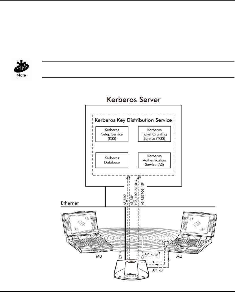
AP-4131 Access Point Product Reference Guide 29
When the AP boots up it contacts the KSS to obtain KDC information. The AP
sends an Authentication Service Request (AS_REQ) to the KDC. The KDC
looks up the username (ESSID in the case of APs), the associated password,
and other authentication information including the current time stamp. If the
AP has provided the correct information the KDC responds with an
Authentication Service Response (AS_REP). These initial Kerberos messages
are used to obtain the client credentials and session key known as the Ticket
Granting Ticket. The AP verifies the information and is authenticated with the
KDC. After the AP validates the message, it turns on its RF services but does
not bridge data packets until the MU has been authenticated.
An MU is required to authenticate with the KDC before the AP allows any RF
bridging. The MU appears to associate but because it has not been
authenticated, the AP does not bridge any non-Kerberos authentication type
packets to the network. The AP acts as a conduit (the AP will proxy the MU
requests/replies to and from the KDC) passing AS_REQ, AS_REP, Ticket
Granting Service Request (TGS_REQ) and Ticket Granting Service Reply
(TGS_REP) between the clients and the KDC until authentication is successful.
Once a ticket is issued and the authentication process is completed, the AP
continues to bridge data with the MU even if the KDC/KSS are unavailable.
Once the ticket expires, the AP/MU stop passing Kerberos data if the
KDC/KSS are still unavailable to issue tickets.
The authentication process for an MU is similar to an AP authentication. The
difference being that the MU/client sends all requests through the AP with
one additional step. The additional step is sending the KDC a TGS_REQ for
RF services. The TGS_REQ message is encrypted with the encryption key that
the MU received during the first part of the authentication process. The ticket
the MU received in the AS_REP includes: the ESSID of the AP whose RF
services it wishes to access. The AP proxies (forwards) the MU request to the
KDC. The KDC verifies the request and responds with a TGS_REP sent to the
MU through the AP which proxies the reply to the MU. The AP proxy does not
read the MU TGS_REQ but replaces the header information with an IP
header (the AP IP address). Conversely, the AP replaces the TGS_REP header
Introduction
30 AP-4131 Access Point Product Reference Guide
with a WNMP header and forwards the response to the MU. Once the MU
has verified the message it prepares an Application Request (AP_REQ) for the
AP. This AP_REQ contains the ticket the KDC has sent to the MU. The AP
decrypts the ticket. If the ticket is valid the AP responds with an AP_REP (the
AP generates and includes128 bit WEP encryption key in the reply) and
permits the MU to bridge data.
The KDC cannot authenticate an MU with administrator as the username.

Introduction
AP-4131 Access Point Product Reference Guide 31
Enabling Kerberos disables Telnet, SNMP and Web services. Configure the
AP through a direct serial connection if needed. Configure SNMP to be "Read
Only" or "Read/Write" from the KSS. Disabling Kerberos returns (Kerberos
disabled is the default setting) Telnet, SNMP and Web services to their
previous setting. If an AP cannot be accessed through a serial connection
and SNMP is not configured for read/write, use of DHCP option 131 is
another way to disable Kerberos.
The KSS in a Spectrum24 environment runs only on a Windows 2000 server
with Active Directory enabled. Future supported platforms include Linux,
Solaris, SCO Unixware and HP-UX.
1.3.11 KSS Open Enrollment
When the KSS startup and KDC authentication completes successfully, the
KSS opens a listening TCP/IP connection port and waits for any AP (several
APs can connect to the KSS concurrently) that requests KSS AP setup services.
Each AP requires an AP Setup Account entry. Open Enrollment mode allows
the system administrator to enter information for APs with the same ESSID
and therefore the same Kerberos Principal. The system administrator creates
an AP Setup Account entry (enter all the Open Enrollment properties
including a Kerberos Principal) in Open Enrollment mode. Complete the
Kerberos account with this Principal in the Kerberos Account database. When
the KSS Listening mode and Open Enrollment is enabled (by selecting a
check box in the Kerberos Setup Service Property page), KSS provides the
default AP Setup Account and the corresponding Kerberos Account to the AP.
A new AP Setup Account record is created for the AP using the default Open
Enrollment properties. The KSS continues to do this until Open Enrollment is
disabled. Access points with a "Disabled" status or expired range entries in
the KSS are not allowed to accept Open Enrollment information. This
provides a tool to block APs that are known to have been stolen or missing.

Introduction
32 AP-4131 Access Point Product Reference Guide
1.3.12 KSS Databases
The KSS has two databases. One database stores valid access points (AP
setup account). The other database stores Kerberos account information
(Kerberos entry account). The AP setup account database stores validation
information for an AP. This database uses the AP MAC address as a Primary
Key. The entry includes the range of time the AP is allowed access and status
information. A Foreign Key entry for a record in the AP setup account is the
Kerberos Principal for this AP. This Foreign Key is used as an index to the
Kerberos Entry account database to retrieve other Kerberos information for
the AP. The Kerberos Entry account database stores specific Kerberos
information for APs. It uses the Kerberos Principal (AP’s ESSID) as its Primary
Key, and it includes other Kerberos network information that an AP needs to
authenticate with the KDC.
When an AP requests information from the KSS, the KSS queries the AP Setup
database to validate the AP. If the AP is valid the KSS will query its Kerberos
Entry account database for the AP’s Kerberos information. The KSS packages
the information and sends it to the AP.
APs with the same ESSID will share common Kerberos Entry account
information since the ESSID is used as an AP Kerberos Principal.
1.3.13 Roaming and Authentication
When an MU authenticates through the KDC it specifies that it wants access
to the AP that it has associated with. When the MU completes the full AS-
REQ/AS-REP, TGT-REQ/TGT-REP, and AP-REQ/AP-REP hand-shake sequence,
it possesses a ticket and a session key (WEP encryption key) for use in
communicating with that AP. However, since the password and the username
are the same for all APs, that ticket decrypts and validates with any AP.
When a MU roams, after it has associated with the new AP it sends to that AP
the same AP-REQ that it sent to the AP that it first authenticated with. The new
AP decrypts the ticket and validates the authenticator in the AP-REQ message.
It then sends back an AP-REP with a new session key to the MU and normal
communication through the new AP can continue.

Introduction
AP-4131 Access Point Product Reference Guide 33
1.3.14 Mixed Mode Security
Mixed mode security allows a single access point to transmit and receive with
mobile units operating with different encryption algorithms (WEP, Kerberos,
EAP-TLS). Using mixed mode, additional access points are not needed to
support mobile units simply because they are using different encryption
schemes.
1.3.15 Web Management Support
A Symbol Spectrum24 Access Point includes an HTTP Web server to allow the
user to access and manage the AP with a standard Java-compatible browser.
This capability provides the user with a Web-based interface for
configuration and firmware download.
Using either NetScape Navigator 4.5 or greater or Microsoft Internet
Explorer 4.0 or greater, point the browser at either the IP address of the AP
or, if the AP is defined in DNS, at the DNS name of the AP. A window opens
that allows the user to access configuration, setup and performance
information for the AP as well as additional diagnostic information.
Disable Kerberos Encryption to use a Web server to configure access
point settings.

Introduction
34 AP-4131 Access Point Product Reference Guide
1.3.16 Management Options
Managing Spectrum24 includes viewing network statistics and setting
configuration options. Statistics track the network activity of associated
MUs and data transfers on the AP interfaces.
The AP requires one of the following to perform a custom installation or
maintain the Spectrum24 network:
• SNMP (Simple Network Management Protocol)
• wired LAN workstation with a Telnet client
• terminal or PC with RS-232 connection and ANSI emulation
Make configuration changes to APs individually. Each AP requires an
individual IP address.
Programmable SNMP Trap Support
The SNMP protocol defines the method for obtaining information about
networks operating characteristics and changing router and gateway
parameters. The SNMP protocol consists of three elements:
• management stations
• management information (MIB)
• a management protocol (SNMP).
Nodes can perform as hosts, routers, bridges or other devices that can
communicate status information. An SNMP Manager is a node that runs the
SNMP management process to systematically monitor and manage the
network. The management station performs network management by
running application management software.
An SNMP trap is an alert to all configured management stations of some
significant event that occurred on the network. The management station
queries all stations for details of each specific event, including what, when
and where the event took place and the current status of the node or
network. The format or structure is defined in the SNMP protocol. The MIB
defines what and who monitors the variables.

Introduction
AP-4131 Access Point Product Reference Guide 35
Using SNMP
The AP includes SNMP agent versions accessible through an SNMP manager
application such as, HP Open View or Cabletron Spectrum MIB browser.
The SNMP agent supports SNMP versions 1 and a subset of version 2, MIB II,
the 802.11 MIB and one Symbol proprietary MIB (Management Information
Base). The SNMP agent supports read-write, read-only or disabled modes.
The AP supports traps that return to the SNMP manager when certain events
occur. The Symbol MIB is available on the Spectrum24 High Rate 11 Mbps
Wireless LAN Software CDROM or from http://www.symbol.com/services/
downloads/download_spec24.html.
Disable Kerberos Encryption to use SNMP to configure access point settings.
Increased MIB Support
The MIB (Management Information Base) has ten categories defining
what the management station needs to understand and which objects the
station manages.

Introduction
36 AP-4131 Access Point Product Reference Guide
Using the UI
The UI (User Interface) is a maintenance tool integrated into the AP.
It provides statistical displays, AP configuration options and firmware
upgrades. Access to the UI requires one of the following:
Telnet Client Access to the AP built-in Telnet server from any interface
including remote Ethernet connections.
See section 2.1.1: ”Using Telnet” on page 37.
Direct Serial
Connection
The AP acts as a DTE device to connect directly to
another DTE device with a null-modem serial cable.
The direct serial access method requires a
communication program with ANSI emulation.
See section 2.1.2: ”Using a Direct Serial Connection” on
page 39.
Dial Up Access The dial-up access method requires a communication
program with ANSI emulation on the remote terminal
or PC. The terminal or PC dials to an AP with a modem
connection. The AP supports connection to a
Hayes-compatible 28,800-baud or faster modem.
See section 2.1.3: ”Using a Dial-Up Connection” on page
40.
SNMP Using a
MIB Browser
Access to the AP SNMP function using a MIB Browser.
Typically a Network Manager uses this feature, however,
Symbol does not recommend accessing the AP using this
interface method.
Web Browser Access to the AP built-in Web server from any AP
interface including Ethernet connections.
See section 2.1.4: ”Using a Web Browser” on page 41.

AP-4131 Access Point Product Reference Guide 37
Chapter 2 Configuring the AP
AP configuration requires setting up a connection to the AP and gaining
access to the UI (User Interface). The methods of accessing the UI are Serial,
Telnet, Web, and SNMP. DHCP is enabled on the AP by default. Initial
network configuration can be obtained from a DHCP server. All except Serial
require the configuration of an IP address.
To access the AP through the serial port and terminal emulation program,
connect to the DB9 serial port using a null modem cable. Set the terminal
emulation program for 19,200 bps, 8 bits, No parity, 1 Stop Bit and No flow
control. Select the AP Installation screen and enter the appropriate IP
configuration parameters for the network.
The dot in front of certain parameters, functions or options (.Antenna
Selection Primary Only) indicates these items update to all APs with the
same Net_ID (ESS) when choosing the Save ALL APs-[F2] option. Users can
perform this option only among the same hardware platforms and same
firmware versions.
2.1 Gaining Access to the UI
The method for establishing access to the UI depends on the connection
used. Select the setup that best fits the network environment.
2.1.1 Using Telnet
Using a Telnet session to gain access to the UI requires that a remote station
have a TCP/IP stack. The remote station can be on the wired or wireless LAN.
To access the AP from the workstation:
1. From the DOS prompt, Telnet to the AP using its IP address:
Telnet xxx.xxx.xxx.xxx

Configuring the AP
38 AP-4131 Access Point Product Reference Guide
2. At the prompt type the password:
Symbol
The password is case-sensitive.
3. Press the ESC key. The AP displays the Main Menu:
Symbol Access Point
MAIN MENU
Show System Summary AP Installation
Show Interface Statistics Special Functions
Show Forwarding Counts Set System Configuration
Show Mobile Units Set RF Configuration
Show Known APs Set Access Control List
Show Ethernet Statistics Set Address Filtering
Show RF Statistics Set Type Filtering
Show Misc. Statistics Set SNMP Configuration
Show Event History Set Event Logging Configuration
Enter Admin Mode
– If the session is idle (no input) for the configured time, the session
terminates.
– Press CTRL+D to manually terminate the session.
4. Proceed to section 2.14.1: ”Update Using TFTP” on page 139 to update
the AP firmware or HTML file or to section 2.2: ”Navigating the UI” on
page 48.

Configuring the AP
AP-4131 Access Point Product Reference Guide 39
2.1.2 Using a Direct Serial Connection
The factory-configured AP accepts a dial-up connection between the AP and
a modem. A UI connection requires a straight-through cable between the
modem and the AP. See section 2.2.3: ”Configuring for Dial-Up to the UI” on
page 53. The AP serial port is a DB-9, 9-pin male connector. The serial port
allows a UI connection to a configuration PC. Connecting the AP directly to a
PC with a 9-pin serial port requires a null modem cable with the following
configuration:
Assuming the UI and serial port are enabled on the AP:
1. Apply Power to the AP.
2. Attach a null modem serial cable from the AP to the terminal or PC
serial port.
3. From the terminal, start the communication program, such as
HyperTerminal for windows.
4. Select the correct COM port along with the following parameters.
There is no password requirement.
emulation ANSI
baud rate 19200 bps
data bits 8
stop bits 1
parity none
flow control none

Configuring the AP
40 AP-4131 Access Point Product Reference Guide
5. Press ESC to refresh the display. The AP displays the Main Menu.
Symbol Access Point
MAIN MENU
Show System Summary AP Installation
Show Interface Statistics Special Functions
Show Forwarding Counts Set System Configuration
Show Mobile Units Set RF Configuration
Show Known APs Set Access Control List
Show Ethernet Statistics Set Address Filtering
Show RF Statistics Set Type Filtering
Show Misc. Statistics Set SNMP Configuration
Show Event History Set Event Logging Configuration
Enter Admin Mode
6. Refer to section 2.12.2: ”Updating Using Xmodem” on page 132 to
update the AP firmware or HTML file or to section 2.2: ”Navigating the
UI” on page 48.
7. Exit the communication program to terminate the session.
2.1.3 Using a Dial-Up Connection
A dial-up connection requires a straight-through cable between the modem
and the AP. The remote PC requires a modem and a communication
program (Microsoft Windows Terminal program).
See Appendix B for information on the modems supported by the AP.
1. Set Modem Connected to Yes in the System Configuration screen.
2. Attach a straight-through serial cable from the AP to the modem.
3. Verify the modem connects to the telephone line and has power.
Refer to the modem documentation for information on verifying
device power.
4. From the remote terminal, start the communication program.

Configuring the AP
AP-4131 Access Point Product Reference Guide 41
5. Select the correct serial port along with the following parameters.
6. Dial out to the AP with the correct telephone number.
No password is required.
7. Press ESC to refresh the display. The AP displays the Main Menu.
Symbol Access Point
MAIN MENU
Show System Summary AP Installation
Show Interface Statistics Special Functions
Show Forwarding Counts Set System Configuration
Show Mobile Units Set RF Configuration
Show Known APs Set Access Control List
Show Ethernet Statistics Set Address Filtering
Show RF Statistics Set Type Filtering
Show Misc. Statistics Set SNMP Configuration
Show Event History Set Event Logging Configuration
Enter Admin Mode
2.1.4 Using a Web Browser
A Web browser is a program used to view Web documents or pages. The
browser retrieves the requested page, interprets its text and displays the page
on a computer screen.
Using a Web browser to gain access to the UI requires the workstation to
have a TCP/IP stack and a Web browser. The remote station can be on the
wired or wireless LAN.
emulation ANSI
baud rate 19200 bps
data bits 8
stop bits 1
parity none
flow control none

Configuring the AP
42 AP-4131 Access Point Product Reference Guide
The Web browser (Internet Explorer 4.0 or greater or Netscape) requires
JavaScript to gain access to the UI.
Setup Network Web Server Help File Access
A network Web server is required to access the Help file from the Access Point
Configuration Management System Web pages. This procedure applies to the
Microsoft Internet Information Server. The network Web server can be
different, if so, some of the procedures differ.
Only Network or System Administration personnel should configure the
network Web server.
To create the Help file on a network Web server:
1. Create a directory on the network Web server for the AP Web Site Help
Files to reside.
Often this subdirectory is C:\InetPub\wwwRoot.
2. Copy the *.gif and *.htm files to this directory/folder.
The files are found in the x:\firmware\AP\AP Web Site\Help File
directory.
Where x is the letter assigned to the computer CDROM drive.
This installation example is for Windows NT 4.0.
3. From the windows Task Bar select Start.
4. From the drop down menu select Programs.
5. From this menu select Microsoft Internet Server(common).

Configuring the AP
AP-4131 Access Point Product Reference Guide 43
6. From this menu select Internet Service Manager to launch the
Internet Information Server Service Manager.
7. Click on the Web service.
Ensure the server WWW service is running.
8. Select Properties.
9. Select Service Properties to display the WWW service properties
for the server.
The WWW Service Properties window opens.
10. Select Directories.
11. Select Add button to open the Directories window.
12. Type the Directory/Folder path of the directory created in step one.
13. Select Virtual Directory.
14. Type a folder alias such as WebHelp and select OK.
15. Check Enable Default Document option.
16. Type S24apHelp.htm as the default document and select Apply.
17. Select OK to exit the window.
18. Test the accessibility to the Help file using a Web browser with a
URL similar to: http://xxx.xxx.xxx.xxx/WebHelp
Where xxx.xxx.xxx.xxx is IP address of the server.
Accessing Web Browser UI
Using a Web browser to gain access to the UI requires the workstation to
have a TCP/IP stack and access to a Web browser. The remote station can
be on the wired or wireless LAN.

Configuring the AP
44 AP-4131 Access Point Product Reference Guide
To ensure the Web Server option is enabled for the AP:
1. Access the UI using a Serial or Telnet connection.
2. From the Main Menu select System Configuration.
3. Verify the Web Server option on the System Configuration screen
is enabled.
4. Select Save-[F1] to save the configuration.
To reset the AP for changes to take effect.
1. Select the Special Functions screen.
2. Select Reset AP.
3. Select Yes at the confirmation prompt.
To enable Help file access, change the Help URL parameter:
1. Select the Special Functions screen
2. Press F3 to view the Firmware Functions Update Menu.
3. Use the TAB or UP/DOWN ARROW key to select the Alter Filename(s)/HELP
URL/TFTP Server.
4. Press ENTER.
5. Use the TAB or DOWN ARROW key to select the .HELP URL field.
6. Type the IP address/URL (Universal Request Locator) of the Web server
and the directory/folder of the Web server for the Help file location.
http://xxx.xxx.xxx.xxx/WebHelp
Where xxx.xxx.xxx.xxx is the IP address of the server.
7. Save the new setting by selecting Save-[F1] option.
8. Select Yes at the confirmation prompt.

Configuring the AP
AP-4131 Access Point Product Reference Guide 45
To access the AP UI using a Web browser from a workstation:
1. From the NCPA properties window set the IP address of the workstation
and the subnet mask. The system tells the user to reboot for property
changes to take effect.
The workstation, in this case, is the workstation or laptop computer running
the Web browser.
2. To verify the connection, ping the AP. At the default DOS prompt, type:
Ping -t xxx.xxx.xxx.xxx
– If the ping receives no response, verify that the hardware
connections, IP address, gateway address and subnet mask are
correct. If correct, contact the site System Administrator for
network assistance.
3. Start a Web browser such as Internet Explorer 4.0 or greater, or
Netscape 3.0 or greater.
Type the IP Address for the associated AP to access the AP using a
Web browser:
http://xxx.xxx.xxx.xxx
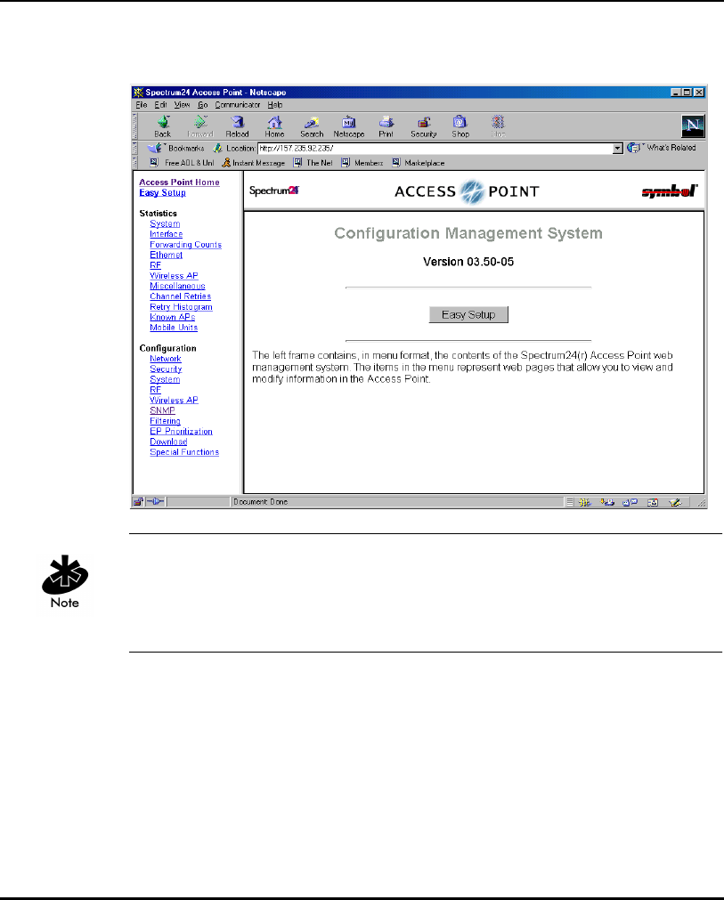
Configuring the AP
46 AP-4131 Access Point Product Reference Guide
4. The Spectrum24 Access Point Configuration Management System main
page displays:
The Web pages look different than the Telnet, Direct Serial or Dial-Up
Connections, but the contents are the same. Access the different pages using
the links located in the left frame. Refer to the online help file for Web page
navigation, page contents and parameter use.
• To view configuration, function or option changes on the Web page(s)
turn off the caching function for the browser being used.
– For Netscape, from the menu bar select Edit, Properties, Advanced
and Cache.
– Select Document in cache is compared to document on network:
Every time.
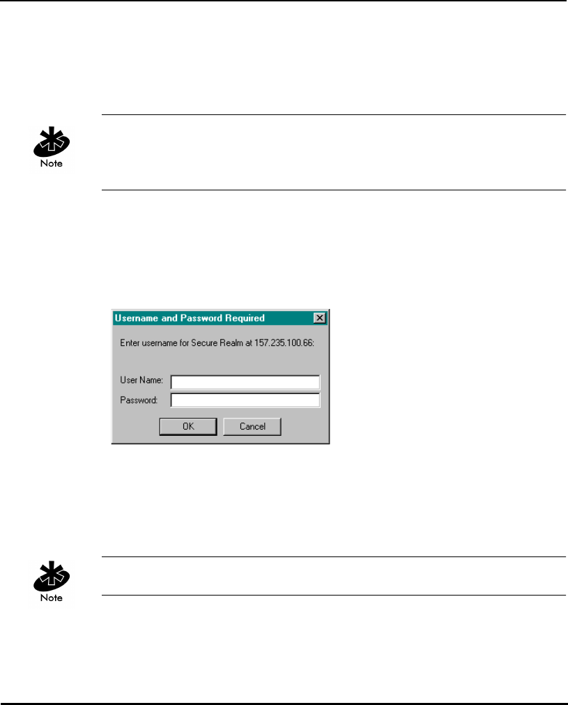
Configuring the AP
AP-4131 Access Point Product Reference Guide 47
– For Internet Explorer, from the menu bar select View, Internet
Options, Temporary Internet files and Settings.
– Select Check for newer versions of stored pages: Every visit to
the page.
If this property/option is not turned off, the browser returns the previous view
of the page without the changes. To ensure the latest version of a Web page
is viewed, set this option in the browser.
• To access help from any Spectrum24 Access Point Configuration
Management System web page, select the Help button located in the top
right-hand corner of each page.
• For access to the Easy Setup and Configuration pages this pop-up
dialogue box appears:
1. Type the AP name.
Symbol Access Point
2. Type the password:
Symbol
The password is case-sensitive.
• Exit the browser to manually terminate the session.

Configuring the AP
48 AP-4131 Access Point Product Reference Guide
2.2 Navigating the UI
The AP displays a Main Menu when gaining access to the UI:
Symbol Access Point
MAIN MENU
Show System Summary AP Installation
Show Interface Statistics Special Functions
Show Forwarding Counts Set System Configuration
Show Mobile Units Set RF Configuration
Show Known APs Set Access Control List
Show Ethernet Statistics Set Address Filtering
Show RF Statistics Set Type Filtering
Show Misc. Statistics Set SNMP Configuration
Show Event History Set Event Logging Configuration
Enter Admin Mode
The top line displays the System Name for the AP (default is Symbol Access
Point) and the name of the configuration screen.
The UI uses the following keystrokes to navigate through the menus
and screens depending on the terminal emulation. For terminal
emulation programs that do not support arrow or function keys, use the
control-character equivalents:
UP ARROW CTRL + O
DOWN ARROW CTRL + I
LEFT ARROW CTRL + U
RIGHT ARROW CTRL + P
F1 CTRL + Q
F2 CTRL + W
F3 CTRL + E
F4 CTRL + R

Configuring the AP
AP-4131 Access Point Product Reference Guide 49
The following conventions also apply when navigating screens
and menus:
• To select menu items, press the key corresponding to the bold letter for
the item (case-sensitive hot key). Press ENTER to select the item.
• Press TAB to scroll through menu items.
• To change menu items, note the bottom line on the screen for
configuration options. For multiple choice options, press the bold letter to
select. To change values, type in the value and press ENTER. If the value
is invalid, the AP beeps and restores the original value. Press TAB to
scroll to next menu item.
• The bottom line on the menu enables menu/screen changes to take
effect. Press TAB to scroll to the item and press ENTER to select.
• When changing values such as System Name or System Passwords,
accept values by scrolling to the next field or pressing ENTER.
• Some screens use function keys to initiate commands. For example,
statistic screens include refresh-[F1] and Timed-[F2] commands to
update the display.
• Some options listed at the bottom of screens indicate possible
commands for a selected item. For example, in the Known APs screen,
highlighting an AP on the list and pressing the [F1] key brings up the
Ping function to Ping that AP.
• Press ESC to exit from submenus.

Configuring the AP
50 AP-4131 Access Point Product Reference Guide
Administration screens include options for saving or clearing data that
appear on the bottom line of the screen. Confirmation prompts include
the following:
2.2.1 Entering Admin Mode
The UI defaults to User when in Serial mode allowing read-only access to the
APs functions (e.g., view statistics). Entering Admin mode provides access to
configuration menus and allows the user to configure the AP.
Entering Admin mode requires the administration password.
1. Select Enter Admin Mode from the Main Menu. The AP prompts for the
administration password:
Enter System Password:
2. Type the default password:
Symbol
The password is case-sensitive.
OK Registers settings but does not save them in NVM
(nonvolatile memory). A reset command returns to
previously saved settings.
Save Saves all settings (including ones not on that screen) to
NVM. This is the same as Save Configuration in the Special
Functions screen.
Save ALL APs Saves the AP installation configuration information to all APs
with the same Net_ID (ESS). This option saves the
configuration changes for the current AP on the Known APs
table to update their configuration and reset after the
configuration has been modified. Users can perform this
option only among the same hardware platforms and same
firmware versions.
Cancel Does not register settings changed in a screen.

Configuring the AP
AP-4131 Access Point Product Reference Guide 51
– If the password is correct, the AP displays the Main Menu with the
Enter Admin Mode menu item changed to Exit Admin Mode.
– If the password is incorrect, the AP continues to display the Main
Menu with the Enter Admin Mode menu item.
Set the System passwords in the Set System Configuration screen.
2.2.2 Changing the Access to the UI
To prevent unauthorized Telnet access, change the configuration access to
the UI. This includes enabling or disabling the Telne t Logins or changing the
System Passwords.
To change Telnet access to the AP:
1. Select Set System Configuration from the Main Menu.
2. Select Telnet Logins.
3. Press the SPACE BAR or LEFT/RIGHT-ARROW keys to toggle between
Enabled and Disabled.
4. Use the TAB key to highlight the SAVE function and press ENTER or press
[F1] to save.
5. The system prompts “Are you sure (Y/N)?” Type Y.
To change the system passwords:
1. Select Set System Configuration from the Main Menu.
2. Press TAB to select System Password Admin or press [F4].

Configuring the AP
52 AP-4131 Access Point Product Reference Guide
3. The Change System Passwords screen displays:
Symbol Access Point
Change System Passwords
User Password *******
Admin Password *******
Save-[F1] Cancel-[ESC]
Password for user access(Monitor only)
4. Change the passwords using the following parameters:
5. Select OK or Save to register settings by writing changes to NVM.
Selecting Save displays a confirmation prompt.
6. The system prompts “Are you sure (Y/N)?” Type Y.
7. Select Cancel or press [ESC] to disregard any changes made to this
screen and return to the previous menu.
User
Password
Allows the user to only monitor or view the screens.
Select any alphanumeric, case-sensitive entry up to
13 characters, the characters selected are displayed
as asterisks. The default password is Symbol.
Admin
Password
Allows the user to view and change the parameters
on each screen. Select any alphanumeric, case-
sensitive entry up to 13 characters, the characters
selected are displayed as asterisks. The default
password is Symbol.

Configuring the AP
AP-4131 Access Point Product Reference Guide 53
2.2.3 Configuring for Dial-Up to the UI
A dial-up connection requires a straight-through cable between the modem
and the AP. The remote PC requires a modem and a communication
program (e.g. Microsoft Windows Terminal program).
Refer to Appendix B for information on the modems supported by the AP.
1. Set Modem Connected to Yes in the System Configuration screen.
2. Attach a straight-through serial cable from the AP to the modem.
3. Verify the modem connects to the telephone line and has power.
Refer to the modem documentation for information on verifying
device power.
4. From the remote terminal, start the communication program.
5. Select the correct serial port along with the following parameters.
6. Dial out to the AP with the correct telephone number.
No password is required.
emulation ANSI
baud rate 19200 bps
data bits 8
stop bits 1
parity none
flow control none

Configuring the AP
54 AP-4131 Access Point Product Reference Guide
7. Press ESC to refresh the display. The AP displays the Main Menu.
Symbol Access Point
MAIN MENU
Show System Summary AP Installation
Show Interface Statistics Special Functions
Show Forwarding Counts Set System Configuration
Show Mobile Units Set RF Configuration
Show Known APs Set Access Control List
Show Ethernet Statistics Set Address Filtering
Show RF Statistics Set Type Filtering
Show Misc. Statistics Set SNMP Configuration
Show Event History Set Event Logging Configuration
Enter Admin Mode
2.2.4 Navigating the UI Using a Web Browser
Refer to the online help file for information on Web Browser navigation and
basic functionality. For file download instructions and the associated file(s)
refer to the Web page:
(http://www.symbol.com/services/downloads/download_spec24.html) and
select Spectrum24® – 11 Mbps DS Firmware, Software, Drivers, Tools
and....
2.3 Access Point Installation
The AP UI includes an AP Installation screen to set basic parameters for a
Spectrum24 network. These parameters include designating a gateway
address that provides the ability to forward messages across routers on the
wired Ethernet.
To install an AP:
1. From the Main Menu select Enter Admin Mode. The system displays
Enter System Password:
2. Enter the default password (unless the password has been changed):
Symbol

Configuring the AP
AP-4131 Access Point Product Reference Guide 55
3. Select AP Installation from the Main Menu:
Symbol Access Point
MAIN MENU
Show System Summary AP Installation
Show Interface Statistics Special Functions
Show Forwarding Counts Set System Configuration
Show Mobile Units Set RF Configuration
Show Known APs Set Access Control List
Show Ethernet Statistics Set Address Filtering
Show RF Statistics Set Type Filtering
Show Misc. Statistics Set SNMP Configuration
Show Event History Set Event Logging Configuration
Enter Admin Mode
4. Verify the AP parameters reflect the network environment. Change them
as needed.
5. Press TAB to scroll to the item and press ENTER to select.
Symbol Access Point
Access Point Installation
.Country Config-[CR] United States
Unit Name Symbol Access Point
IP Address 157.235.95.174
.Additional Gateways
.Gateway IP Address 0.0.0.0 0.0.0.0 0.0.0.0
0.0.0.0 0.0.0.0
.Subnet Mask 255.255.0.0 0.0.0.0 0.0.0.0
111.111.12.1
.DNS IP Address 0.0.0.0
.Net_ID (ESS) 101
.Additional DNS
.Antenna Selection Full Diversity 157.235.95.229 0.0.0.0
.DHCP/BOOTP Enabled
OK-[CR] Save-[F1] Save All APs-[F2] Cancel-[ESC]
(Most parameters take effect only after being saved and AP is reset)

Configuring the AP
56 AP-4131 Access Point Product Reference Guide
If this is the first time the AP has been installed or has been moved to a new
country, verify that the proper country specific code is entered for the AP.
Refer to Appendix D for a list of supported country codes.
Verify that the proper country specific code is entered for the AP to conform to
the set of rules defined in national or international regulations.
Where:
Country Config Configure the AP for the user’s country. This
item displays a list of country names. Use the
TAB key to highlight the appropriate country
and press ENTER. The AP displays Are You
Sure? Enter Y for yes. The display refreshes and
displays the new country. Prior to setting the
Country Config code, certain AP features are
not available. See Appendix D for AP country
code information.
Unit Name The AP name.
IP Address The network-assigned Internet Protocol address
of the AP.
Gateway IP Address IP address of a router the AP uses on the
Ethernet as its default gateway.
Additional
Gateways
The IP address of the additional gateways used.
Access up to seven gateways.

Configuring the AP
AP-4131 Access Point Product Reference Guide 57
Subnet Mask The first two sets of numbers specify the network
domain, the next set specifies the subset of
hosts within a larger network and the final set
specifies an individual computer. These values
help divide a network into subnetworks and
simplify routing and data transmission. The
subnet mask defines the size of the subnet.
DNS IP Address Primary Domain Name Server IP address.
Additional DNS The IP address of the additional DNS servers
available. A maximum of two additional DNS
servers are available.
Net_ID (ESS) The unique 32-character, alphanumeric, case-
sensitive wireless network identifier of the AP.
Antenna Selection Enables selection of antenna diversity. Options
are:
•Full Diversity
– the radio receives on the primary or
secondary antenna (which ever has the
best signal strength) and transmits on
the last antenna it received on.
•Primary only
– the radio transmits and receives on the
primary antenna only.
•Secondary only
–the radio transmits and receives on the
secondary antenna only
•Rx Diversity
– the radio receives on the primary or
secondary antenna (whichever has the
best signal strength) and transmits on
the primary only.

Configuring the AP
58 AP-4131 Access Point Product Reference Guide
5. In the Antenna Selection field, use the SPACE BAR or LEFT/RIGHT-
ARROW keys to toggle between Full Diversity, Primary Only, Secondary
Only
, or Rx Diversity.
6. Select OK or Save to register settings by writing changes to NVM.
Selecting Save displays a confirmation prompt.
7. Select Save ALL APs or press [F2] to save the AP installation
configuration information to all APs with the same Net_ID (ESS).
This option saves the configuration changes for the current AP on the
Known APs table to update their configuration and reset after the
configuration has been modified. Users can perform this option only
among the same hardware platforms and firmware version.
Additional
Gateways
The IP address of the additional gateways used.
Access up to seven gateways.
DHCP/BOOTP Enables or Disables selection of DHCP/BOOTP.
The options are:
•Enabled
– DHCP and BOOTP interoperate,
whichever response the AP selects first
becomes the server allocating the
information.
•DHCP Only
– Only DHCP responses will be accepted
by the AP.
•BOOTP Only
– Only BOOTP responses will be accepted
by the AP. If both DHCP and BOOTP
services are required, do not selected
BOOTP Only.
•Disabled
– Disables BOOTP and DHCP; network
configuration is manually entered.

Configuring the AP
AP-4131 Access Point Product Reference Guide 59
8. The system prompts Warning Update, save, and reset all APs in the Known AP Menu?
yes no Typ e Y.
9. Select Cancel-[ESC] to disregard any changes made to this screen and
return to the previous menu.
2.4 Configuring System Parameters
The AP provides configuration options for how the unit operates,
including security access and interface control. Some parameters do not
require modification.
1. Select Set System Configuration from the Main Menu to display:
Symbol Access Point
System Configuration
Channel 9 .Access Control Disabled
Auto Channel Select Disabled .Type Filtering Disabled
.Ethernet Timeout 0
WNMP Functions Enabled
.Telnet Logins Enabled .AP-AP State Xchg Enabled
.Encryption Admin Any Ethernet Interface On
RF Interface On
.Agent Ad Interval 0 Default Interface Ethernet
.S24 Mobile IP Disabled
.Mobile-Home MD5 key ******* Max Associated MUs 127
.MU-MU Disallowed Off
.Web Server Enabled
Modem Connected No
Inactivity Timeout 5
System Password Admin-[F4]
OK-[CR] Save-[F1] Save All APs-[F2] Cancel-[ESC]
Save, then reset AP for new value to take effect.

Configuring the AP
60 AP-4131 Access Point Product Reference Guide
Once the country has been configured (Country Config) on the AP
Installation screen the channel can be set manually or automatically.
2. Configure the AP system settings as required:
Channel Specifies the channel that is requested by all
associated MUs when associating with this
particular access point.
Auto Channel
Select
Normally run once during initial installation.
1. Power up the AP and select Auto Channel
Select (ACS). Press <spacebar> or
<-/-> to enable or disable. To save
configuration, select F1.
2. On the next power up, the AP scans all
channels and selects a non-overlapping
channel with the fewest APs. The AP saves
the channel in FLASH (the power LED
flashes during this process) and turns off
ACS. The AP flashes its LEDs as if powering
up and returns to a STATUS-flashing state
when complete.
Non-overlapping channels have 25Mhz
separation beginning at the first allowed channel
for the country (for the US and most of Europe,
channels 1, 6 & 11 are used). The channel
selection process groups all APs heard over RF
into non-overlapping bands. Then compares the
quantities of APs with received signal strengths
above the average signal strength. Ties are
broken based on the AP's MAC address.

Configuring the AP
AP-4131 Access Point Product Reference Guide 61
Ethernet
Timeout
Disables radio interface if no activity is detected
on the Ethernet line after the seconds indicated
(30-255). The AP disassociates MUs and prevents
further associations until it detects Ethernet activity.
The default value 0 disables this feature. The 1
value detects if the 10/100Base-T line goes down.
If the value is set to 2 and the WLAP has
connected to the Root AP, the WLAP sends a WLAP
Alive BPDU on the Ethernet line every WLAP Hello
Time seconds to allow WLAPs on the Ethernet line
to detect its existence.
If the value is set to 3, the WLAP tracks the WLAP
Alive BPDU. If the BPDU is missing for WLAP Hello
Time seconds, the WLAP state changes to WLAP
Lost on Ethernet. Once the WLAP Alive BPDU is
detected, the WLAP resets and starts over.
When the Ethernet connection is broken the AP
clears the MU table and disables the RF interface
until the Ethernet connection comes up.
Teln et Login s Specifies if the AP accepts or rejects Telnet Logins.
The default value is Enabled.

Configuring the AP
62 AP-4131 Access Point Product Reference Guide
Encryption
Admin
Indicates which interface can change the
encryption keys and the encryption key index.
Without admin privileges users cannot access the
encryption maintenance page to change the
encryption keys.
Any allows users with admin privileges to change
encryption keys through any interface.
Serial allows users with admin privileges to
change this parameter and encryption keys only
through the Serial port.
See section 2.4.1 “Encryption Administration” on
page 66 for all AP encryption administration
parameters for all interfaces (Serial, Telnet, HTML
Web browser and SNMP).
Agent Ad
Interval
Specifies the interval in seconds between the
mobility agent advertisement transmission.
S24 Mobile IP If enabled, this feature allows MUs to roam
across routers. The Mobile IP feature is not
available for the access point if either Kerberos or
EAP-TLS have been enabled as access point
security measures.
Mobile-Home
MD5 key
Secret key used for Mobile-Home registration
and authentication.
Web Server Enables the use of a Web based browser to access
the UI instead of HyperTerminal or Telnet
applications.
An AP Reset is required for this feature to take
effect.

Configuring the AP
AP-4131 Access Point Product Reference Guide 63
Access
Control
Allows the user to set one of three Access Control
modes: Disabled, Allowed, or Disallowed.
• When Disabled (default) is selected, no filtering
is performed.
• When Allowed is selected, only MAC addresses
specified in the Access Control List are allowed
to associate with the AP.
• When Disallowed is selected, only MAC
addresses not specified in the Disallowed
Addresses List (Address Filtering) are allowed
to associate with the AP.
Type Filtering Specifies filter type for packets received either
Forward/Discard or Disabled.
The default value is Disabled.
WNMP
Functions
Specifies if the AP can perform WNMP functions.
The default value is Enabled.
AP-AP State
Xchg
Specifies AP-to-AP communication exchanged.
Max
Associated
MUs
Specifies the maximum number of MUs (127) that
are allowed to associate with the access point.
MU-MU
Disallowed
If enabled, mobile units associated with the same
AP are not allowed to communicate with each
other.
Modem
Connected
The default setting is No. Set to Yes when using a
dial-up configuration.
Inactivity
Timeout
The inactivity time on the UI that causes the AP to
terminate the connection while using a modem.
The default is 5 minutes from a 0 to 100-minute
range.
The 0 value indicates no time-out.

Configuring the AP
64 AP-4131 Access Point Product Reference Guide
System
Password
Admin
Allows the user to change the passwords for the
AP. This screen can be accessed only when the AP
is in Telnet mode.
Serial mode provides read-only privileges and
does not allow the user to view this screen.

Configuring the AP
AP-4131 Access Point Product Reference Guide 65
3. To enable or disable interfaces on the AP, modify the following
parameters:
4. Verify the values set reflect the network environment.
Change as needed.
5. Select OK or Save to register settings by writing changes to NVM.
Selecting Save displays a confirmation prompt.
6. Select Save ALL APs or press [F2] to save the System Configuration
information to all APs with the same Net_ID (ESS).
This option saves the configuration changes for the current AP, sends two
WNMP messages to all other APs on the Known APs table to update their
configuration and resets after the configuration has been modified.
Users can perform this option only among the same hardware platforms
and firmware version.
7. The system prompts Warning Update, save, and reset all APs in the Known AP Menu?
yes no Typ e Y.
8. Select Cancel-[ESC] to disregard any changes made to this screen and
return to the previous menu.
Ethernet
Interface
Enables or disables wired Ethernet.
The default value is On.
RF Interface Enables or disables radio. The default value is On.
Default Interface Specifies the default interface (Ethernet, WLAP or
Reserved) that the AP forwards a frame to if the AP
cannot find the address in its forwarding database.
The default interface is Ethernet. The AP defaults to
Ethernet when Reserved is selected.

Configuring the AP
66 AP-4131 Access Point Product Reference Guide
2.4.1 Encryption Administration
The ability to change, view or restrict access to encryption administration
settings depends on the Encryption Admin configuration parameter. The
options for this parameter are Serial and Any. These options are
configurable via the Serial UI located in the System Configuration screen.
The Encryption Admin parameter effects all interfaces supported by the AP
(Serial, Telnet, HTML Web browser and SNMP). The tables in this section are
useful for determining the access level (to encryption parameters) available
to the user through each type of interface. For example, if the Encryption
Admin configuration parameter is selected (in the System Configuration
screen) the user (with admin privileges) sets the option to Serial. The user
can View/Modify (through the Serial UI) and can View Only through the
Teln et U I .
A Telnet client can change the setting from Any to Serial. Once set to Serial,
Telnet has no access to this parameter. When the Encryption Admin
configuration parameter is set to Any, WEP Encryption configuration is
allowed on all interfaces.

Configuring the AP
AP-4131 Access Point Product Reference Guide 67
Encryption Parameter Access to Telnet and Serial Interfaces
Encryption Parameter Access to Web Interface
Parameter Access Method Interface Serial
Encryption Admin System Configuration
Screen
Telnet/Serial
View/Modify
Serial UI - View/Modify
Telnet UI - View Only
Shared Key Special Functions
Screen/Configure
WEP Encryption
Telnet/Serial
View/Modify
Serial UI - View/Modify
Telnet UI - View Only
Key Width Special Functions
Screen/Configure
WEP Encryption
Telnet/Serial
View/Modify
Serial UI - View/Modify
Telnet UI - View Only
Encryption Key ID Special Functions
Screen/Configure
WEP Encryption
Telnet/Serial
View/Modify
Serial UI - View/Modify
Telnet UI - View Only
Encryption Keys Special Functions
Screen/Configure
WEP Encryption
Telnet/Serial
Modify
Serial UI - Modify
Telnet UI - No Access
Parameter Access Method Interface Serial
Encryption
Administration
Configuration - Security Setup View/ Only View Only
Shared Key Configuration - Security Setup View/Modify View Only
Key Width Configuration - Security Setup View/Modify View Only
Encryption Key Configuration - Security Setup
- Encryption Key Setup
View Only View Only
Encryption Keys Configuration - Security Setup
- Encryption Key Setup
Modify Only No Access

Configuring the AP
68 AP-4131 Access Point Product Reference Guide
Encryption Parameter Access for SNMP Interface
Parameter Access Method Interface Serial
apEncryptAdmin s24dsap.mib -
apConfigMgmt -
apSystemConfig group
View Only View Only
apWEPAlgorithm s24dsap.mib -
apConfigMgmt -
apRFConfig group
View/Modify View Only
ap128WEPKeyValue
(1..4)
s24dsap.mib -
apConfigMgmt -
ap128WEPKeyTable
Modify Only No Access
dot11PrivacyInvoked 802dot11.mib -
dot11smt -
dot11PrivacyTable
View/Modify View Only
dot11Authentication
Algorithm
802dot11.mib -
dot11smt -
dot11Authen..Algorit..
Tabl e
View Only View Only
dot11Authentication
AlgorithmEnable
802dot11.mib -
dot11smt -
dot11Authen..Algorit..
Tabl e
View Only View Only
dot11WEPDefaultKey
Value
802dot11.mib -
dot11smt -
dot11WEPDefualtKey
Tabl e
Modify Only No Access

Configuring the AP
AP-4131 Access Point Product Reference Guide 69
2.4.2 System Password Administration
This screen allows the network administrator to configure the passwords for
the AP. The user password allows the user to Telnet into the AP or use the
serial port and have read-only privileges. Accessing the UI in an Admin
mode session through the serial port the session does not time-out.
Entering the Admin mode with Telnet and Serial Port interfaces enabled
allows the Admin mode on both interfaces. This can cause a security breach
if a user, without admin privileges, Telnets into the AP while the admin
security level is enabled.
1. To access and change the System Passwords, select System Password
Admin-[F4] from the System Configuration Menu. The Change System
Passwords screen displays:
Symbol Access Point
Change System Passwords
User Password *******
Admin Password *******
Save-[F1] Cancel-[ESC]
Password for user access(Monitor only)

Configuring the AP
70 AP-4131 Access Point Product Reference Guide
2. Change the passwords using the following parameters:
3. Select Save to register settings by writing changes to NVM.
Selecting Save displays a confirmation prompt.
4. Select Cancel-[ESC] to disregard any changes made to this screen and
return to the previous menu.
User Password Allows the user to monitor or view the screens. Select
any alphanumeric, case-sensitive entry up to 13
characters, the characters selected are displayed as
asterisks. The default password is Symbol.
Admin
Password
Allows the user to view and change the parameters
on each screen. Select any alphanumeric, case-
sensitive entry up to 13 characters, the characters
selected are displayed as asterisks. The default
password is Symbol.

Configuring the AP
AP-4131 Access Point Product Reference Guide 71
2.5 Configuring Radio Parameters
The AP automatically configures most radio parameters. Only advanced
users, Symbol trained users or Symbol representatives should adjust the
radio parameters for the AP or the options in the RF Configuration screen.
1. Select Set RF Configuration from the Main Menu to display:
Symbol Access Point
RF Configuration
.DTIM Interval 10 WLAP Mode Disabled
.BC/MC Q Max 10
.Max Retries (d) 15 WLAP Priority 8000 hex
.Max Retries (v) 5 WLAP Manual BSS ID 00:00:00:00:00:00
.Multicast Mask (d) 09000E00 hex
.Multicast Mask (v) 01005E00 hex WLAP Hello Time 20
.Beacon Interval 100 K-us WLAP Max Age 100
.Accept Broadcast ESSID Enabled WLAP Forward Delay 5
.MU Inactivity Timeout 60 min. WLAP MU Table Aging Time 240 min.
.Rate Control
11 Mb/s Optional
5.5 Mb/s Optional
2 Mb/s Required
1 Mb/s Required
.RTS Threshold 2347 bytes
.Short RF Preamble Disabled
.Extended Range 0 mi. Tx Power Control Full
EPP Setup - [F3]
EIAP Setup - [F4]
OK-[CR] Save-[F1] Save All APs-[F2] Cancel-[ESC]
The frequency of DTIM packets as a multiple of TIM packets. Range(1..255)
The dot in front of certain parameters, functions or options (for example .Rate
Control) indicates these items update to all APs with the same Net_ID (ESS)
when choosing the Save ALL APs-[F2] option. Users can perform this option
only among the same hardware platforms and same firmware versions.

Configuring the AP
72 AP-4131 Access Point Product Reference Guide
2. Configure the settings as required:
DTIM Interval Configure DTIM packet frequency as a multiple of
beacon packets. The DTIM Interval indicates how
many beacons equal one cycle. Users should not
modify this setting or risk damaging the
configuration.
BC/MC Q Max Determines the memory allocated for the queue
used in the AP to temporarily hold broadcast/
multicast messages. Unit measure is in packets and
corresponds to maximum-sized Ethernet packets.
The default is 10.
Max Retries (d) The maximum allowed retries before aborting a
single data packet transmission. The default is 15.
Users should not modify this setting or risk
damaging the configuration.
Max Retries (v) The maximum allowed retries before aborting a
single voice packet transmission. The default is 5.
Users should not modify this setting or risk
damaging the configuration.
Multicast Mask
(d)
Supports broadcast download protocols for any MU,
typically Point-of-Sale terminals, requiring
the expedited download of a new operating
image over the network instead of using a local
nonvolatile drive.
All multicast downstream data packets that match
the top 32 bits of the multicast mask are forwarded
immediately instead of being queued for
transmission at the next DTIM interval.
Multicast Mask
(v)
Supports broadcast, or party-line, voice
communications. All multicast downstream data
packets that match the top 32 bits of the multicast
mask are forwarded immediately instead of being
queued for transmission at the next DTIM interval.

Configuring the AP
AP-4131 Access Point Product Reference Guide 73
Beacon Interval The time between beacons in Kilo-microseconds.
The default is 100. Avoid changing this parameter as
it can adversely affect performance.
Accept
Broadcast ESSID
Allows the AP to respond to any station sending
probe packets with the industry-standard broadcast
ESS. If Enabled, this feature allows industry-standard
devices interoperability. The AP probe response
includes the ESS and information about the network.
By default, this feature is Enabled and the AP
responds only to stations that know the ESSID. This
helps preserve network security. MUs require using
Broadcast ESS to use this function.
MU inactivity
Timeout
Allows industry-standard device interoperability by
specifying the time the AP allows for MU inactivity.
A Spectrum24 AP recognizes MU activity through
data packet transmission and reception, and
through scanning. Spectrum24 MUs conduct active
scanning. Other industry-standard MUs might
conduct passive scans and a Spectrum24 AP can
classify them as inactive.

Configuring the AP
74 AP-4131 Access Point Product Reference Guide
Rate Control Defines the data transmission rate,
the defaults are:
• 11 Mbps - Optional
• 5.5 Mbps - Optional
• 2 Mbps - Required
• 1 Mbps - Required.
The defaults allow the AP to automatically select the
the best transmit rate allowed by the conditions.
These settings allow a mixture of
1 Mbps, 2 Mbps, 5.5 Mbps and 11 Mbps radios in
the same network.
Any combination of the data rates can be
selected as Optional, Required or Not Used,
but it is essential to set the lowest selected rate
to Required.
All IEEE 802.11 broadcast and management frames
are sent out on the lowest required data rate.
RTS Threshold Request to send threshold (256 – 2347). Allows the
AP to use RTS (Request To Send) on frames longer
than the specified length.
The default is 2347 Bytes.
Extended Range Enables APs to bridge over long distances using high
gain antennas. The Extended Range setting adds 11
microseconds per mile to the ACK timeout value.
Should be used for coverage areas greater than one
mile. RF propagation through the air is about 5.5
microseconds per mile (one way). Use 11
microseconds as a round-trip value per mile.

Configuring the AP
AP-4131 Access Point Product Reference Guide 75
WLAP Mode Specifies the APs wireless-AP operation status.
Enabled
• the AP sets up automatically for wireless
operation. The AP can operate in any of these
configurations: Wireless, Repeater or Ethernet
Bridge.
Disabled
• no wireless operation possible. Default setting.
Link Required. At power up:
• If the WLAP is the Root AP, an Ethernet connection
is required.
• If the WLAP is a designated WLAP, association to
the Root AP is required.
During normal operation:
• If the Ethernet connection is lost, the Root
AP resets.
• If the WLAP association is lost, the designated
WLAP resets.
WLAP Priority Allows a user to determine the Root and the
designated WLAP in wireless operation. Concatenate
the priority value as the most significant portion of
the MAC address. An AP with a lower numerical
value for priority is more likely to become the root AP.
The default is 8000 hex from the 0 - 0xFFFF range.

Configuring the AP
76 AP-4131 Access Point Product Reference Guide
WLAP Manual
BSS ID
Specifies the BSS_ID of a particular WLAP
and forces the current AP to associate only with that
WLAP.
If setting the WLAP Manual BSS_ID to the current
BSS_ID, the current AP jumps into Functional State
immediately and waits for an Association Request
from the other WLAP. See section 3.8: ”Radio
Statistics” on page 176. This feature speeds up the
association process and minimizes confusion when
more than two WLAPs try to associate with each
other.
WLAP Hello Time Sets the time lapse, in seconds, between Config
BPDU packets sent to the Root AP by a designated
WLAP. The default is 20 seconds.
If the Root AP fails to hear from the designated WLAP
within the WLAP Max Age time, it removes the
designated WLAP from its interface table.
The WLAP Hello Time of the Root AP overwrites the
WLAP Hello Time of designated WLAPs. The WLAP
Hello Time does not refer to the time lapse between
beacons sent by the Root AP. If a designated WLAP
fails to receive a beacon, it knows that its Root AP
has lost the Root status.
WLAP Max Age Defines the time interval, in seconds, before
discarding aged configuration messages. This
causes a disconnection between the two WLAPs. The
recommended value is a multiple of the WLAP Hello
Time. The default is 100 seconds.
The WLAP Max Age of the Root AP overwrites the
WLAP Max Age of designated WLAPs.

Configuring the AP
AP-4131 Access Point Product Reference Guide 77
WLAP Forward
Delay
Specifies the time, in seconds, to prevent an AP from
forwarding data packets to and from an interface
during initialization. The WLAPs involved and the
wireless operation state, see section 3.8: ”Radio
Statistics” on page 176, affect the WLAP Forward
Delay time. This delay ensures that all WLAP nodes
are heard. The default is 5 seconds per wireless
operation state.
The WLAP Forward Delay of the Root AP overwrites
the WLAP Forward Delay of designated WLAPs.
WLAP MU Table
Aging Time
Allowable WLAP Mobile Unit aging timeout in
minutes. The time out limit is from 1 to 86400
minutes. Default is 240 minutes.
Short RF
Preamble
Determines whether the AP uses a short or long
preamble. The preamble is approximately 8 bytes of
the packet header generated by the AP and attached
to the packet prior to transmission.
The preamble length is transmission data rate
dependant. The short preamble is 50% shorter than
the long preamble.
This feature is only available on high rate DSSS
hardware. Non-high rate DSSS hardware (e.g. the
BAY Stack 660) can not enable the short preamble
function and can not see, receive or acknowledge
messages from short preamble enabled version 2.0
hardware. Disable this feature in a mixed hardware
network and use the long preamble. MUs and APs
are required to have the same Short RF Preamble
settings for interoperability. The default is Disabled.
Tx Power Control Allows the system administrator to reduce the
coverage area to facilitate greater AP density
resulting in greater wireless network capacity.
Available settings are: Full (default), 30mW, 15mW, 5mW
and 1mW. These values are approximate.

Configuring the AP
78 AP-4131 Access Point Product Reference Guide
EPP Setup - [F3] Enhanced Packet Prioritization (EPP) allows system
administrators the ability to prioritize packet
transmissions from an AP to MUs. Media content
(streaming video, phones etc.) can be prioritized
over a heavily loaded access point. EPP allows
prioritization of the media for smooth delivery, at the
cost of reduced bandwidth. Mission critical
transmissions can be prioritized allowing the
customization of access point bandwidth. If EPP
services are not needed, they should be turned off to
maximize raw AP throughput. Default is Enabled.
EIAP - [F4] Enhanced Interference Avoidance Properties (EIAP)
allows system administrators the ability to reserve a
portion of the access points transmission bandwidth
for BlueTooth terminal network traffic. EIAP also
enables an access point to reduce MU transmission
interference by optimizing MU transmit rates.
Default is Enabled.

Configuring the AP
AP-4131 Access Point Product Reference Guide 79
3. Verify the values set to reflect the network environment.
Change them as needed.
4. Select OK or Save to register settings by writing changes to NVM.
Selecting Save displays a confirmation prompt.
5. Select Save ALL APs or press [F2] to save the RF Configuration
information to all APs with the same Net_ID (ESS).
This option saves the configuration changes for the current AP, sends two
WNMP messages to all other APs on the Known APs table to update their
configuration and resets after the configuration has been modified.
Users can perform this option only among the same hardware platforms
and firmware version.
6. The system prompts Warning Update, save, and reset all APs in the Known AP Menu?
yes no Typ e Y.
7. Select Cancel-[ESC] to disregard any changes made to this screen and
return to the previous menu.
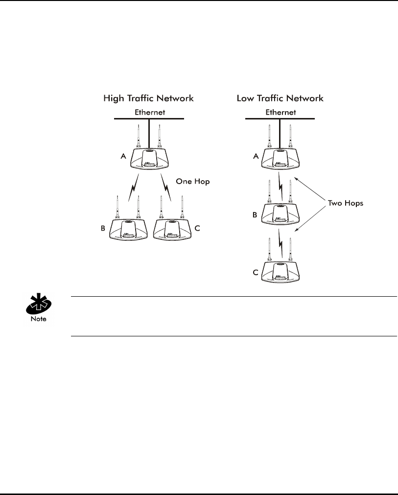
Configuring the AP
80 AP-4131 Access Point Product Reference Guide
2.5.1 Wireless AP Operation Parameters
The AP supports up to four WLAP interfaces. Symbol recommends using one
WLAP as an interface on high traffic networks and no more than two WLAPs
for low traffic networks. Excessive channel contention causes the WLAP to
miss beacons from the Root APs shown in the example.
Kerberos, EAP-TLS and the Mobile IP feature are not available when the
access point is operating in WLAP mode.
See section 4.9: ”LED Indicators” on page 198 for indication of AP status. If
more than two WLAPs operate in a repeater configuration, Symbol
recommends the WLAPs with the lowest WLAP IDs be placed on the wired
network.
To avoid forming a loop, per the IEEE 802.1d Spanning Tree Protocol, the
Wireless WLAP associates with only one wired WLAP.
1. Set the default interface for AP A to Ethernet.
2. Set the default interface for AP B to Ethernet.
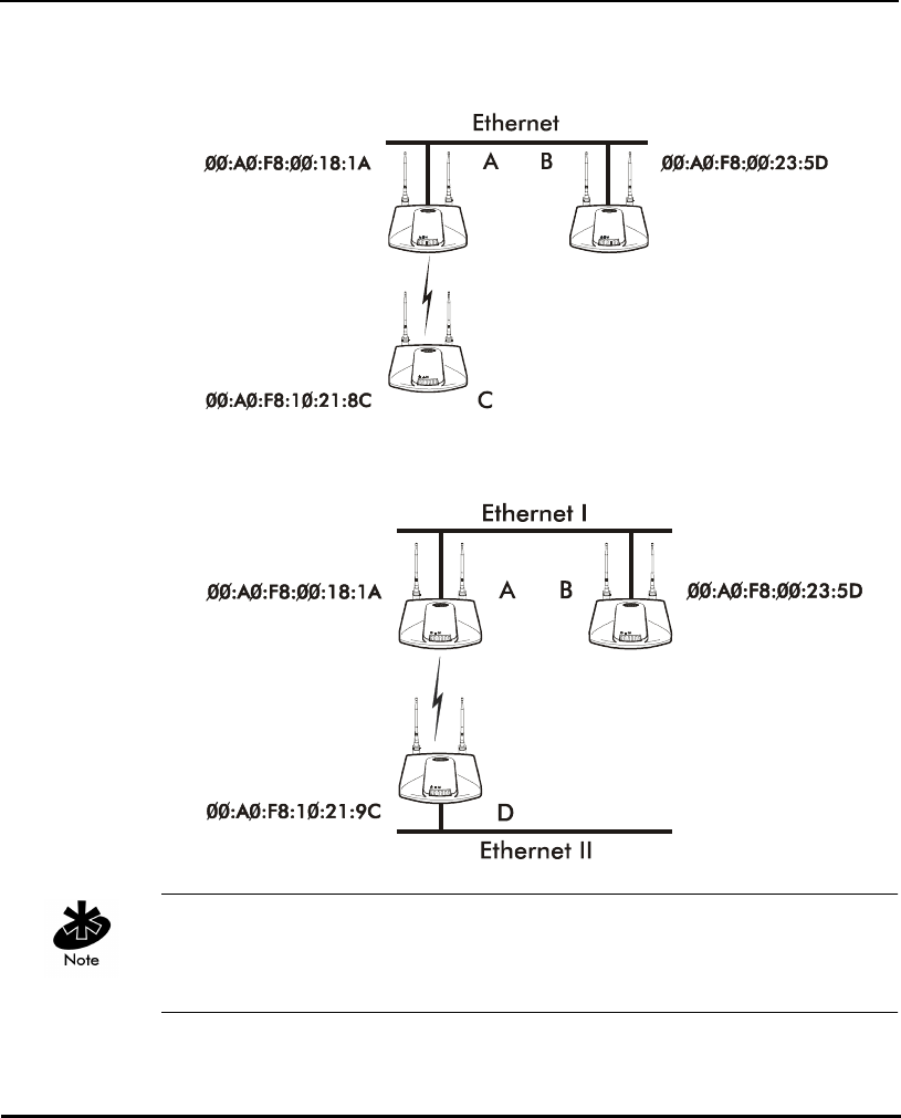
Configuring the AP
AP-4131 Access Point Product Reference Guide 81
3. Set the default interface for AP C to WLAP.
This allows the MUs to roam and transmit data between AP B and C.
If an AP functions as a bridge between wired LANs, Symbol recommends one
LAN contain all the lower WLAP IDs.
In WLAP mode, APs and MUs are required to have the same Preamble
settings for interoperability. Additionally, the root AP is required to be running
before the “leaf” or WLAP connection is established.

Configuring the AP
82 AP-4131 Access Point Product Reference Guide
To configure the AP for wireless operation:
1. Select Set RF Configuration from the Main Menu.
2. Configure the settings as required:
WLAP Mode Specifies the APs wireless-AP operation status.
Enabled
• the AP sets up automatically for wireless
operation. The AP can operate in any of
these configurations: Wireless, Repeater or
Ethernet Bridge.
Disabled
• no wireless operation possible. Default
setting.
Link Required
At power up:
• If the WLAP is the Root AP, an Ethernet
connection is required.
• If the WLAP is a designated WLAP,
association to the Root AP is required.
During normal operation:
• If the Ethernet connection is lost, the Root
AP resets.
• If the WLAP association is lost, the
designated WLAP resets.
WLAP Priority Allows a user to determine the Root and the
designated WLAP in wireless operation.
Concatenate the priority value as the most
significant portion of the MAC address. An AP
with a lower numerical value for priority is more
likely to become the root AP. The default is 8000
hex from the 0 - 0xFFFF range.

Configuring the AP
AP-4131 Access Point Product Reference Guide 83
WLAP Manual
BSS_ID
Specifies the BSS_ID of a particular WLAP and
forces the current AP to associate only with
that WLAP.
If setting the WLAP Manual BSS_ID to the
current BSS_ID, the current AP jumps into
Functional State immediately and waits for an
Association Request from the other WLAP. See
section 3.8: ”Radio Statistics” on page 176.
This feature speeds up the association process
and minimizes confusion when more than two
WLAPs try to associate with each other.
WLAP Hello Time Sets the time lapse, in seconds, between
Config BPDU packets sent to the Root AP by a
designated WLAP. The default is 20 seconds.
If the Root AP fails to hear from the designated
WLAP within the WLAP Max Age time, it
removes the designated WLAP from its
interface table.
The WLAP Hello Time of the Root AP overwrites
the WLAP Hello Time of designated WLAPs. The
WLAP Hello Time does not refer to the time
lapse between beacons sent by the Root AP. If a
designated WLAP fails to receive a beacon, it
knows that its Root AP has lost the Root status.
WLAP Max Age Defines time, in seconds, before discarding
aged configuration messages. This causes a
disconnection between the two WLAPs. The
recommended value is a multiple of the WLAP
Hello Time. The default is 100 seconds.
The WLAP Max Age of the Root AP overwrites
the WLAP Max Age of designated WLAPs.

Configuring the AP
84 AP-4131 Access Point Product Reference Guide
WLAP Forward
Delay
Specifies the time, in seconds, to prevent an AP
from forwarding data packets to and from an
interface during initialization. The WLAPs
involved and the wireless operation state affect
the WLAP Forward Delay time (see section 3.8:
”Radio Statistics” on page 176). This delay
ensures all WLAP nodes are heard. The default
is 5 seconds per wireless operation state.
The WLAP Forward Delay of the Root AP
overwrites the WLAP Forward Delay of
designated WLAPs.
WLAP MU Table
Aging Time
Allowable WLAP Mobile Unit aging timeout in
minutes. The time out limit is from 1 to 86400
minutes. Default is 240 minutes.

Configuring the AP
AP-4131 Access Point Product Reference Guide 85
2.5.2 Enhanced Packet Prioritization (EPP)
Enhanced Packet Prioritization (EPP) enables system administrators to
prioritize packet transmissions from an AP to MUs. For example, media
content (streaming video, phones etc.) can be prioritized over a heavily
loaded access point. EPP allows prioritization of the media for smooth
delivery or selected data traffic for expedited delivery at some cost in
aggregate bandwidth through the access point.
Phone traffic by default is prioritized over data traffic whether EPP Control is
Enabled or not. If the only network requirement is for phone prioritization
over data, Disable EPP Control. If EPP Control is Enabled, assign a phone
traffic priority appropriate to site requirements.
To c o nf i gu r e EP P:
1. Click F3 from the RF Configuration screen.
The Configure Enhanced Packet Prioritization screen displays.
Symbol Access Point
Configure Enhanced Packet Prioritization
Enhanced Packet Prioritization Enabled
FTP Traffic 10 TCP Port 1022 30
HTTP Traffic 30 TCP Port 1023 30
HTTPS Traffic 30 TCP Port 65537 30
Media Over Browser Traffic 10 TCP Port 65537 30
SSH Traffic 30 TCP Port 65537 30
Phone Traffic 10 TCP Port 65537 30
Telnet Traffic 30 TCP Port 65537 30
Video Traffic 30 TCP Port 65537 30
OK-[CR] Save-[F1] Save All APs-[F2] Cancel-[Esc]
2. Prioritize network traffic by assigning either 10 to those data types
requiring high network throughput priority or 30 to those data types
receiving standard priority.
3. Enter numbers for the TCP Ports as needed.

Configuring the AP
86 AP-4131 Access Point Product Reference Guide
For data types not listed, classify them by using the Port number
corresponding to that data type. Use 65537 as a code defining a port as
not used, otherwise assign port values of 1 through 1023. Up to 10
assigned port numbers can be priority controlled.
4. Assign priorities to the TCP Ports supporting network traffic.
5. Save the changes as required.
If EPP services are not needed they should be turned off to maximize access
point throughput.
2.5.3 Enhanced Interference Avoidance Properties (EIAP)
The Enhanced Interference Avoidance Properties (EIAP) feature allows system
administrators to optimize access point network transmissions in respect to
MU throughput and Bluetooth terminal activity within a Spectrum24 network.
To c o nf i gu r e EI AP:
1. Click F4 from the RF Configuration screen.
The Configure Enhanced Interference Avoidance Properties screen
displays.
Symbol Access Point
Configure Enhanced Interference Avoidance Properties
Adaptive Interference Processing Enabled
802.15 (draft) Bluetooth Co-existence 0 ms
OK-[CR] Save-[F1] Save All APs-[F2] Cancel-[Esc]
2. Enable Adaptive Interference Processing to allow the access point to use
the highest MU transmit rate available in the network to reduce the
period of time transmissions can be damaged by interference. If network
interference is anticipated, Enhanced Interference Avoidance Properties
should be enabled.

Configuring the AP
AP-4131 Access Point Product Reference Guide 87
3. 802.15 (draft) Bluetooth Co-existence allows access points and MUs to
share Spectrum24 network resources with Bluetooth RF terminals. The
802.15 (draft) Bluetooth Co-existence value is communicated to MUs via
access point beacons. When a non zero-value is entered, Symbol
802.11b devices stop transmitting for the duration of that interval. This
allows Bluetooth devices (which are very low power) an opportunity to
communicate. This feature should only be used with Bluetooth terminals
because it reduces the total throughput of all 802.11 devices.

Configuring the AP
88 AP-4131 Access Point Product Reference Guide
2.6 Encryption Configuration and Key Maintenance
The Encryption Key Maintenance screens allow the user to configure the
encryption keys used for the site network. The Key Width determines which
encryption Key screen displays. To enable the Open System option, select
Disabled for Shared Key from the System Summary screen.
This table shows the association capability with the selected Key Width.
Each 40-bit encryption key is a subset of the respective 128-bit encryption
key. The first 40 bits of each encryption key is the same for the respective
40-bit and 128-bit encryption keys. When a 40-bit encryption key is
changed the first 40 bits of the respective 128-bit key is also changed.
Consequently, when a 128-bit encryption key is changed the first 40 bits of
the 40-bit encryption key is changed. Moreover, configuring the encryption
Keys using the SNMP Trap Manager overrides the Key value(s) for the AP(s)
accessed by the SNMP Trap Manager.
Symbol provides a total of four Encryption Keys. Each key enables
encryption between the AP and an associated MU with the same encryption
Key and Key value.
AP Selected WEP
Algorithm
MU Selected WEP
Algorithm
Association Status
Open (disable) Open Associated
Open (disable) 40 No Association
Open (disable) 128 No Association
40 Open No Association
40 40 Associated
40 128 Associated, but cannot
transmit data
128 Open No Association
128 40 Associated, but cannot
transmit data
128 128 Associated

Configuring the AP
AP-4131 Access Point Product Reference Guide 89
Two screens are available, one for 40-bit encryption and one for 128-bit
encryption.
Considerable care is required when assigning keys. Keys have to be in the
same order with the same value per key for the AP and MU to authenticate
data transmission using encryption.
Example: An AP uses Key 1 with a value of 1011121314. The associated MU
requires the same Key 1 to have the value of 1011121314.
An MU configured using Windows XP’s Wireless Network tool uses a Key
Index value range of 0 - 3. Consequently, an XP configured MU should use a
key index 1 value lower than the value set for the access point. For example,
if the AP key index is 2, the MU key index should be set to 1.
To access the Encryption Key Maintenance screen determined by the
Key Width chosen, select Encryption Key Maintenance from the WEP
Encryption Configuration screen.
Key values are displayed in plain text while being entered. After saving the
keys are displayed as all zeros (default display is all zeros). Keys are saved
only if they are not all zeros.

Configuring the AP
90 AP-4131 Access Point Product Reference Guide
2.6.1 40-Bit WEP Encryption
Select 40-bit from the Key Width field of the WEP Encryption Configuration
screen, and select the Encryption Key Maintenance option to display the
Encryption Key Maintenance screen.
Symbol Access Point
Encryption Key Maintenance
*
PassKey ******************
.Key 1 * 00000 00000
.Key 2 00000 00000
.Key 3 00000 00000
.Key 4 00000 00000
* = Active Key
Note: This screen has Write-Only access. Keys can be set but not displayed. Zeros
are displayed to indicate the field sizes. A line containing all zeros allows
the corresponding key to remain unchanged.
OK-[CR] Save-[F1] Save All APs-[F2] Cancel-[ESC]
Each key has 40-bits available to the user for configuration and are
displayed in two 20-bit segments. The remaining 24 IV (initialization vector)
bits are factory set and not user configurable.
1. Enter a PassKey (optional) as a plain text representation of the WEP keys
in the Encryption Key Maintenance screen.
The access point transforms the PassKey string into set of 4 WEP keys
using MD5 algorithms. When <Enter> is pressed, the WEP keys appear
in the WEP key fields and are the active keys. Once the keys appear in
the WEP fields, the screen behaves as if the keys were entered manually.
Pressing [F1] saves the keys to flash (keys remain active) and pressing
[ESC] discards the keys.
The PassKey provides an easy way to enter WEP key data without having
to remember the entire 40-bit (10 character) or 128-bit (26 character)
Hex digit string.

Configuring the AP
AP-4131 Access Point Product Reference Guide 91
The PassKey can be no longer than 32 characters in length.
2. Select the desired key and enter the new value to change the Key value.
3. Verify and change the values as needed to reflect the network
environment.
4. Select OK or Save to register settings by writing changes to NVM.
Selecting Save displays a confirmation prompt.
5. Select Save ALL APs or press [F2] to save the Encryption Key
Maintenance information to all APs with the same Net_ID (ESS).
This option saves the configuration changes for the current AP, sends two
WNMP messages to all other APs on the Known APs table to update their
configuration and resets after the configuration has been modified.
Users can perform this option only among the same hardware platforms
and firmware version.
6. The system prompts Warning Update, save, and reset all APs in the Known AP Menu?
yes no Typ e Y.
7. Select Cancel-[ESC] to disregard any changes made to this screen and
return to the previous menu.
Key values are displayed in plain text while being entered. Once saved, the
keys are displayed as all zeros (default display is all zeros).

Configuring the AP
92 AP-4131 Access Point Product Reference Guide
2.6.2 128-Bit WEP Encryption
Select 128-bit from the Key Width field of the WEP Encryption Configuration
screen, and select the Encryption Key Maintenance option to display the
Encryption Key Maintenance screen.
Symbol Access Point
Encryption Key Maintenance
PassKey ********************
.Key 1 * 00000 00000 0000 0000 0000 0000
.Key 2 00000 00000 0000 0000 0000 0000
.Key 3 00000 00000 0000 0000 0000 0000
.Key 4 00000 00000 0000 0000 0000 0000
* = Active Key
Note: This screen has Write-Only access. Keys can be set but not displayed. Zeros
are displayed to indicate the field sizes. A line containing all zeros allows
the corresponding key to remain unchanged.
OK-[CR] Save-[F1] Save All APs-[F2] Cancel-[ESC]
Each key has 104-bits available to the user for configuration and are
displayed in two 20-bit segments and four 16-bit segments. The remaining
24 IV (initialization vector) bits are factory set and not user configurable.
1. Enter a PassKey (optional) as a plain text representation of the WEP keys
in the Encryption Key Maintenance screen.
The access point transforms the PassKey string into set of 4 WEP keys
using MD5 algorithms. When <Enter> is pressed, the WEP keys appear
in the WEP key fields and are the active keys. Once the keys appear in
the WEP fields, the screen behaves as if the keys were entered manually.
Pressing [F1] saves the keys to flash (keys remain active) and pressing
[ESC] discards the keys.
The PassKey provides an easy way to enter WEP key data without having
to remember the entire 40-bit (10 character) or 128-bit (26 character)
Hex digit string.

Configuring the AP
AP-4131 Access Point Product Reference Guide 93
The PassKey can be no longer than 32 characters in length.
2. Select the desired key and enter the new value to change the Key value.
3. Verify and change the values as needed to reflect the network
environment.
4. Select OK or Save to register settings by writing changes to NVM.
Selecting Save displays a confirmation prompt.
5. Select Save ALL APs or press [F2] to save the Encryption Key
Maintenance information to all APs with the same Net_ID (ESS).
This option saves the configuration changes for the current AP, sends two
WNMP messages to all other APs on the Known APs table to update their
configuration and resets after the configuration has been modified. This
option is only used with the same hardware and firmware platforms.
6. The system prompts Warning Update, save, and reset all APs in the Known AP Menu?
yes no Typ e Y.
7. Select Cancel-[ESC] to disregard any changes made to this screen and
return to the previous menu.
When Kerberos is enabled, the AP communicates with each MU using a
different 128-bit session key. When Kerberos is disabled, the access point
defaults to previous Encryption algorithm set in the RF Statistics page. Reset
the access point twice to ensure the access point Encryption algorithm is the
same as the associated MU(s).

Configuring the AP
94 AP-4131 Access Point Product Reference Guide
2.6.3 Manual Kerberos Authentication Configuration
The Configure Kerberos Authentication screen allows the network
administrator to change or verify the AP parameters for Kerberos
authentication. If a DHCP server is not available use the Configure Kerberos
Authentication screen to manually configure and enable Kerberos, save and
reset the AP. If the KSS has been installed on the Kerberos server, resetting the
AP allows the KSS to complete the Kerberos configuration and start the
Kerberos authentication services. If a DHCP server is available enable
Kerberos using DHCP server options found in section 1.3.3: ”DHCP Support”
on page 15. These options can enable Kerberos on the AP, and setup the
KDC name, KSS name and port number.
Enabling Kerberos disables Telnet, SNMP and Web services. Configure the
AP through a direct serial connection. Disabling Kerberos returns (Kerberos
Disabled is the default setting) Telnet, SNMP, and Web services to their
previous setting. If an AP cannot be accessed through a serial connection
and SNMP is not configured for read/write, use DHCP option 131.

Configuring the AP
AP-4131 Access Point Product Reference Guide 95
1. To access and enable the Kerberos configuration, select Configure
Kerberos from the Special Functions Menu. The Configure Kerberos
Authentication screen displays:
Symbol Access Point
Configure Kerberos Authentication
Kerberos Enabled
KSS Port 34567
KSS Secret *******
KSS Name/IP Address ksssrv
*** If not using a KSS, please configure the following items.
KDC Server Name/IP Address krbtgt
Backup KDC Name/IP Address kdc2
Realm Name APFW.SYMBOL.COM
User ID ap3
Password *******
OK-[CR] Save-[F1] Cancel-[ESC]
Enable Kerberos
2. Verify the KSS port/name to enable Kerberos. Modify as needed.
3. Verify the KDC name.
Only enter a KDC Server Name/IP Address, Backup KDC Name/IP Address, Realm Name, User ID
and Password if not using a KSS.
The MU does not display the Kerberos login password screen if the wrong
KDC name is entered in the AP Authentication screen.
4. Verify the User ID matches the ESSID.

Configuring the AP
96 AP-4131 Access Point Product Reference Guide
5. Verify the Password matches the password in the KDC and AP.
6. Select OK or Save to register settings by writing changes to NVM. Selecting
Save displays a confirmation prompt.
7. Select Cancel-[ESC] to disregard any changes made and return to the
previous menu.
Kerberos Allows the user to enable Kerberos authentication. Telnet,
SNMP, and Web services are disabled when Kerberos is
enabled. Default setting is Disabled.
KSS Port TCP Port number the AP uses to communicate with the
KSS.
KSS Secret Allows the user to change the default Encryption key.
KSS Name/
IP Address
Name of the Kerberos Setup Service for the AP.
KDC Server
Name/IP
Address
The name of the server housing the Key Distribution
Center (KDC).
Backup KDC
Name/IP
Address
The name of the server (if any) used as the backup server
for the Key Distribution Center (KDC).
Realm Name The Kerberos Realm Name (similar to a DHCP domain
name).
User ID The KDC user ID the AP uses to authenticate (ESSID of the
AP and the Kerberos Principal).
Password The KDC password the AP uses to authenticate

Configuring the AP
AP-4131 Access Point Product Reference Guide 97
2.6.4 Configuring EAP-TLS Support
The Extensible Authentication Protocol-Transport Level Security (EAP-TLS)
feature affords access points and their associated MU’s an additional
measure of security for data transmitted over the Spectrum24 wireless
network. Using EAP-TLS, authentication between devices is achieved through
the exchange and verification of certificates. EAP-TLS can be used in mixed
mode security support with Kerberos and WEP when 128-bit WEP is used.
EAP-TLS is only supported on mobile devices running Windows XP. The
EAP-TLS program is required to run on a Windows 2000 Server. Refer to the
system administrator for information on configuring a Windows 2000 Server
for EAP-TLS support.
EAP-TLS is a mutual authentication method whereby both the MU and access
point are required to prove their identities. Like Kerberos, the user loses
device authentication if the server cannot provide proof of device
identification.
To configure for EAP-TLS support for a Spectrum24 access point:
1. Select Configure EAP-TLS from the Security Configurations field of the
Special Functions menu.

Configuring the AP
98 AP-4131 Access Point Product Reference Guide
The Configure Authenticator screen displays.
Configure Authenticator
EAP-TLS/RADIUS Enabled
Quiet Period 60
Tx Period 30
Re-authentication Enabled
Re-auth Period 3600
Re-auth Max 2
Supplicant Timeout 30
Server Timeout 30
Max Req Retries 2
IAS Name/IP Address ias
Backup IAS Name/IP ias2
IAS Password *******
OK-[CR] Save-[F1] Cancel-[ESC]
Enable EAP-TLS

Configuring the AP
AP-4131 Access Point Product Reference Guide 99
2. Configure the EAP-TLS authentication settings as required:
EAP-TLS/RADIUS When enabled, the access point assumes the role
of authenticator. The access point proxies the
MU’s requests to authenticate with the EAP server.
Default is Disabled.
Quiet Period The time the access point waits before attempting
to acquire an MU. Default is 60 seconds.
Tx Period Defines the length of time the access points waits
for an MU’s response once the access point
requests an MUs identity. Default is 30 seconds.
Re-authentication When enabled, the access point forces the MU to
re-authenticate after the re-authentication period.
Default is Enabled.
Re-auth Period Defines the length of time a MU is waits before
initiating re-authentication attempts.
Default is 3600 seconds.
Re-auth Max Defines the number of MU re-authentications
attempts permitted. Default is 2. If exceeded, the
access point fails MU re-authentication.
Supplicant
Timeout
Time permitted for a response from the
authenticating MU. Default is 30 seconds.
Server Timeout Time permitted for a response from the EAP-TLS
authentication server. Default is 30 seconds.
Max Req Retries Defines the maximum number of times an access
point re-transmits an EAP request. Default is 2.
IAS Name/IP
Address
Name or IP address of the authentication server.
Backup IAS
Name/IP
Name or IP address of the backup authentication
server.
IAS Password The shared secret password between the access
point and authentication server.

Configuring the AP
100 AP-4131 Access Point Product Reference Guide
2.6.5 Configuring Mixed Mode Security
Mixed mode security allows a single access point to transmit and receive
data with mobile units operating with different encryption algorithms. In
mixed mode, additional APs are not needed to support mobile units simply
because they are using different encryption schemes. 128-bit WEP, Kerberos
and EAP-TLS can be used together to provide mixed mode security.
To configure mixed mode security:
1. In the access point System Summary screen, set the Shared Key option
to Enabled and the Key Width to 128 bit. Click [F1] to save the settings.
2. From the Special Functions Menu screen, select the Configure
Kerberos option. From the Configure Kerberos Authentication screen,
set the Kerberos option to Enabled. Enter the KSS Name/IP address.
3. Click [F1] to save the settings. Reboot.
If the Key Width is not set to 128 bit, an error message displays (once the
settings are saved and Kerberos is enabled) stating 128 bit must be enabled.
Consequently, 128 bit is required for mixed mode security to be used. When
Kerberos is set, the key width defaults to 128-bit.

Configuring the AP
AP-4131 Access Point Product Reference Guide 101
SNMP and Mixed Mode Security
The configuration of SNMP shared key WEP is set with the MIB file. The
objects involved include:
• apRFConfig.apWEPAlgorithm
Edit the AP serial UI entry using the Key Width field within the AP System
Summary screen.
• ap128bWEPKeyTable.ap128bWepKeyValue (1..4)
Edit the AP serial UI entry by selecting 128-bit within the Key Width field
of the WEP Encryption Configuration screen.
• apSharedKeyEnable
Set the Shared Key item within the System Summary screen to Enabled.
apSharedKeyEnable is a new feature to the Symbol proprietary MIB. This
object controls the Shared Key Enable/Disable option.

Configuring the AP
102 AP-4131 Access Point Product Reference Guide
2.7 Configuring the SNMP Agent
The SNMP agent functions as a command responder and is a multilingual
agent responding to SNMPv1, v2c and v3 managers (command generators).
The factory default configuration maintains SNMPv1/2c support of the
community names, hence providing backward compatibility. However,
Agents with the default configuration are "Open" with minimum security
enabled.
The access point generates traps for a set of pre-defined conditions. SNMP
trap generation is programmable on a trap-by-trap basis and can be
Enabled/Disabled by the user. The current version of the agent supports
SNMPv1 traps only.
Refer to the Symbol MIB (s24dsap.mib) available on the Spectrum24 High
Rate 11 Mbps Wireless LAN Software CDROM or from
http://www.symbol.com/services/downloads/download_spec24.html.
The AP supports s24dsap.mib, MIB-II and 802dot1x.mib files.

Configuring the AP
AP-4131 Access Point Product Reference Guide 103
1. Select Set SNMP Configuration from the Main Menu to AP display:
Symbol Access Point
SNMP Configuration
.SNMP Agent Mode Enabled SNMPv3 Security Admin-[CR]
.Read-Only Community (v1/2c) *******
.Read-Write Community (v1/2c) *******
.Trap Host1 157.235.95.10
.Trap Host2
.All Traps Enabled
Generic Traps: Enterprise-Specific Traps:
.Cold Boot Disabled .Radio Restart Disabled
.Authentication failure Disabled .Access Cntrl Violation Disabled
.MU State Change Disabled
.DHCP Change Disabled
.WLAP Connection Change Disabled
.Security Protocol Errors Disabled
OK-[CR] Save-[F1] Save All APs-[F2] Cancel-[ESC]
(Use the space bar or left/right cursor keys to change)

Configuring the AP
104 AP-4131 Access Point Product Reference Guide
2. Configure the settings as required:
SNMP Agent
Mode
Defines the SNMP agent mode:
Disabled disables SNMP functions, while Enabled
allows SNMP functions.
Read-Only
Community
User-defined password string up to 31characters
identifying users with read-only privileges.
Read-Write
Community
User-defined password up to 32 characters for users
with read/write privileges.
Trap Host1 The Trap Host1 IP address or Name.
Trap Host2 The Trap Host2 IP address or Name.
All Traps Enables or disables all trap operations.
The default value is Disabled.
Cold Boot Sends a trap to the manager when the AP cold boots.
The default value is Disabled.
Authentication
failure
Indicates that community strings other than those
specified for the Read-Only and Read/Write
Community were submitted.
The default value is Disabled.
SNMPv3
Security Admin
Displays the SNMPv3 User Security Configuration
screen used for viewing and configuring SNMPv3
security for user groups. SNMPv1/2c users should not
select SNMPv3 Security Admin unless configuring users
for SNMPv3 operations. Changing the factory
configuration could adversely effect SNMPv1/2c
operation.
Radio Restart Sends a trap to the manager for radio restart.
The default is value Disabled.
Access Cntrl
Violation
Sends a trap to the manager when an ACL violation
occurs. The default value is Disabled.

Configuring the AP
AP-4131 Access Point Product Reference Guide 105
MU State
Change
If enabled, the following enterprise-specific traps are
generated:
• MU Association Additions
Indicates when a device has been added to the list
of access point associated MUs.
• MU Association Removals
Indicates when a device has been removed from
the list of access point associated MUs.
DHCP Change If enabled, the following enterprise-specific traps are
generated:
• Gateway Address change
Indicates the gateway address for the router has
changed.
• IP Address Change
Indicates the IP address for the AP has changed.
• IP Address Lease is up
Informs the user the IP address leased from the
DHCP server is about to expire.

Configuring the AP
106 AP-4131 Access Point Product Reference Guide
3. Verify the values reflect the network environment. Change as needed.
4. Select OK or Save to register settings by writing changes to NVM.
Selecting Save displays a confirmation prompt.
5. Select Save ALL APs or press [F2] to save the SNMP Configuration
information to all APs with the same Net_ID (ESS).
This option saves the configuration changes for the current AP, sends two
WNMP messages to all other APs on the Known APs table to update their
configuration and resets after the configuration has been modified.
Users can perform this option only among the same hardware platforms
and firmware version.
WLAP
Connection
Change
If enabled, the following enterprise-specific traps are
generated:
•Root WLAP Up
Indicates that the Root AP connection is setup and
ready to forward data.
•Root WLAP Lost
If the current WLAP fails to receive a Beacon packet
from its Root AP within one second, it considers the
Root AP lost. The WLAP eventually resets itself to
reestablish the network topology.
• Designated WLAP Up
Indicates that the Designated WLAP connection is
setup and ready to forward data.
• Designated WLAP Lost
If the current WLAP fails to receive a Config BPDU
packet from its Designated WLAP for MAX AGE
time, it considers the Designated WLAP lost.
Security
Protocol Errors
If enabled, the following enterprise-specific traps are
generated:
• AP failed to authenticate
• MU exceeded time allowed to authenticate.

Configuring the AP
AP-4131 Access Point Product Reference Guide 107
6. The system prompts Warning Update, save, and reset all APs in the Known AP Menu?
yes no Typ e Y.
7. Select Cancel-[ESC] to disregard any changes made to this screen and
return to the previous menu.

Configuring the AP
108 AP-4131 Access Point Product Reference Guide
2.7.1 Configuring SNMPv3 Security
SNMPv3 defines a method of access point data control known as the View-
Based Access Control Model (VACM). It is a means of restricting access to a
particular subset of data based on the security level used in the request and
specifies whether access should be allowed.
SNMPv3 defines data access for each user (user group) based on identity
and security level. Write access and read access to proprietary information
can be limited to selective users increasing configuration alternatives in
respect to sensitive data.
Select SNMPv3 Security Admin from the SNMP Configuration screen to
display the SNMP User Security Configuration screen. Use this window to
view defined user groups, their context (group definition) and security level.
Symbol Access Point
SNMPv3 User Security Configuration
User/Group Name Context Name Security Level
-------------------------------------------------------------------------------------
1) guest noAuthNoPrivacy
2) Symbol noAuthNoPrivacy
3) user3 admin3 authNoPrivacy
4) user4 admin4 authPrivacy
5) user5 admin5 authNoPrivacy
6) user6 admin6 authPrivacy
Configure User/Group-[CR] Save All APs-[F2] Exit-[ESC]

Configuring the AP
AP-4131 Access Point Product Reference Guide 109
To configure the properties of a user group:
1. Highlight the specific user group and select Enter.
The User/Group Security Configuration screen displays for the selected
user group.
User/Group3 Security Configuration
User/Group3-------------------------------------------------------------------------------
User/Group Name user3
Context Name admin3
Read View Full
Write View Full
Security Level authNoPrivacy
Authentication Protocol HMAC-MD5-96
Authentication Password *******
Privacy Protocol None
Privacy Password *******
OK-[CR] Save -[F1] Cancel-[ESC]
2. Configure the settings as required for the selected user/group:
User/Group Name The name assigned to the user/group.
Context Name Defines the access context for the user/group
member(s) and should relate to the security
privileges assigned (admin, guest etc.).
Read View Defines the read view privileges assigned to the
user/group.
Write View Defines the write view privileges assigned to the
user/group.
Security Level Defines the security level assigned to the
user/group. Options include authNoPrivacy
(password protection but no data security),
authPrivacy (password protection and data
encryption) and noAuthNoPrivacy (no security).

Configuring the AP
110 AP-4131 Access Point Product Reference Guide
Authentication
Protocol
Defines the authentication protocol and security
privileges for the user/group. Options include
HMAC-MD5-96 (default MD5 authentication
protocol), HMAC-SHA-96 (no data protection, but
does have password protection) and None (no
protection).
Authentication
Password
Password required to initiate the authentication
scheme defined in the Authentication protocol
field. The password is required to be at least 8
characters in length.
Privacy Protocol Defines the None (no data security) or DES (full
data security) SNMP security options.
Privacy Password Password used to enable the SNMP Privacy
Protocol. The password is required to be at least
8 characters in length.

Configuring the AP
AP-4131 Access Point Product Reference Guide 111
2.8 ACL and Address Filtering
Only 512 maximum combined entries are available for the ACL. The three
modes available (Disabled, Allowed, and Disallowed) are selected in the
Access Control section of the System Configuration Menu.
Symbol Access Point
System Configuration
Channel 11 .Access Control Disabled
Auto Channel Select Disabled .Type Filtering Disabled
.Ethernet Timeout 0
WNMP Functions Enabled
.Telnet Logins Enabled .AP-AP State Xchg Enabled
.Encryption Admin Any Ethernet Interface On
RF Interface On
.Agent Ad Interval 0
.S24 Mobile IP Disabled Default Interface Ethernet
.Mobile-Home MD5 key *******
Max Associated MUs 127
.MU-MU Disallowed Off
.Web Server Enabled
.Modem Connected No
.Inactivity Timeout 5
System Password Admin-[F4]
OK-[CR] Save-[F1] Save All APs-[F2] Cancel-[ESC]
Save, then reset AP for new value alue to take effect.
The dot in front of certain parameters, functions or options (for example
.Access Control) indicates these items update to all APs with the same Net_ID
(ESS) when choosing the Save ALL APs-[F2] option. Users can perform this
option only among the same hardware platforms and same firmware
versions.

Configuring the AP
112 AP-4131 Access Point Product Reference Guide
There are three mutually exclusive modes used by the AP to control
association: Disabled, Allowed and Disallowed.
Access
Control
Address Filtering
List
Access Control List Results
Disabled The presence or
absence of MAC
addresses does
not affect the
results.
The presence or
absence of MAC
addresses does not
affect the results.
No Filtering All MAC
addresses are allowed to
associate.
Allowed The presence or
absence of MAC
addresses does
not affect the
results.
MAC addresses
present
Only MAC addresses in
the Access Control list are
allowed to associate.
Disallowed MAC addresses
present
The presence or
absence of MAC
addresses does not
affect the results.
Only MAC addresses
NOT in the Address
Filtering list are allowed to
associate.
Allowed The presence or
absence of MAC
addresses does
not affect the
results.
Empty No Associations
Disallowed Empty The presence or
absence of MAC
addresses does not
affect the results.
No Filtering. All MAC
addresses are allowed to
associate.

Configuring the AP
AP-4131 Access Point Product Reference Guide 113
2.8.1 Configuring the ACL
The ACL supports adding MU entries by individual MAC address or by a
range of MAC addresses.
1. Select the Set Access Control List option from the Main Menu to display:
Address Type? range individual
2. Use the UP/DOWN-ARROW keys to toggle between range and
individual.
2.8.2 Range of MUs
To select a range of MAC addresses:
1. Type in the minimum MAC address as the top value:
00:0A:F8:F0:01:01
2. Press ENTER to accept the value; use the DOWN-ARROW key to select
the maximum value.
3. Type in the maximum MAC address in the bottom value:
00:0A:F8:F0:02:FF
4. Press ENTER to accept the value; use the DOWN-ARROW key to
select OK.
5. Press ENTER. The UI displays:
Symbol Access Point
Ranges of Allowed Mobile Units
Min Address Max Address
00:A0:F8:F0:01:01 00:A0:F8:F0:02:FF
00:A0:F8:29:10:02 00:A0:F8:29:11:00
Delete-[F1] Add-[F2] Save All APs-[F3] Exit-[ESC]
6. Verify values reflect the network environment. Change them as needed.

Configuring the AP
114 AP-4131 Access Point Product Reference Guide
7. Select Delete-[F1] to delete a range of Mobile Units.
8. Select Add-[F2] to add a range of Mobile Units.
9. Select Save ALL APs or press [F3] to save the Ranges of Allowed Mobile
Units information to all APs with the same Net_ID (ESS).
This option saves the configuration changes for the current AP, sends two
WNMP messages to all other APs on the Known APs table to update their
configuration and resets after the configuration has been modified.
Users can perform this option only among the same hardware platforms
and firmware version.
10. The system prompts Warning Update, save, and reset all APs in the Known AP Menu?
yes no Typ e Y.
11. Select Cancel-[ESC] to disregard any changes made to this screen and
return to the previous menu.
When users enable the Access Control option, all MUs within the specified
range can associate with the AP. Specify additional ranges as needed or add
to the ACL using individual address entries.

Configuring the AP
AP-4131 Access Point Product Reference Guide 115
2.8.3 Adding Allowed MUs
The Access Control List screen provides a facility to add MUs to the ACL.
1. Select the Set Access Control List option from the Main Menu to display:
Address Type? range individual
2. Use the UP/DOWN-ARROW keys to toggle between range and
individual. Select individual.
3. Press Add-[F2]. The AP prompts for a MAC address.
00:00:00:00:00:00
4. Enter the MAC address.
Users can enter MAC addresses without colons.
5. Select Save ALL APs or press [F4] to save the Adding Allowed MU
information to all APs with the same Net_ID (ESS).
This option saves the configuration changes for the current AP, sends two
WNMP messages to all other APs on the Known APs table to update their
configuration and resets after the configuration has been modified.
Users can perform this option only among the same hardware platforms
and firmware version.
6. The system prompts Warning Update, save, and reset all APs in the Known AP Menu?
yes no Typ e Y.
7. Select Cancel-[ESC] to disregard any changes made to this screen and
return to the previous menu.
2.8.4 Removing Allowed MUs
The Allowed Mobile Units screen provides a facility to remove MUs from
the ACL.
1. Highlight the entry using the UP/DOWN-ARROW keys.
2. Press Delete - [F1].

Configuring the AP
116 AP-4131 Access Point Product Reference Guide
2.8.5 ACL Options
To switch between Allowed, Disallowed or Disabled options locate the ACL in
the System Configuration screen.
Use ACL options from the Set System Configuration menu.
Where:
1. Select Set System Configuration from the Main Menu.
2. Press TAB to select Access Control.
3. Press SPACE BAR to select Allowed, Disallowed or Disabled.
4. Select Save to save changes.
2.8.6 Removing All Allowed MUs
The AP provides a facility to remove all MUs from the ACL.
1. Select Special Functions from the Main Menu.
2. Select Clear ACL.
2.8.7 Load ACL from MU List
This option from the Special Functions menu takes all associated MUs and
creates an ACL from them. This builds an ACL without having to manually
type addresses. Edit the ACL using the add and delete functions.
1. Set the ACL option to Disable.
2. Select Special Functions from the Main Menu.
3. Select Load ACL from MU List to add associated MU addresses the ACL.
Option Description
Allowed to allow only MUs with their MAC address in the ACL to
associate with AP.
Disallowed to prevent MUs in the Address Filters list from associating
with the AP.
Disabled allows any MU to associate with the AP (no ACL/filters
are in effect).

Configuring the AP
AP-4131 Access Point Product Reference Guide 117
2.8.8 Load ACL from File
This option loads an ACL from a user defined ACL file (AP_ACL.TXT) entered
on the secondary screen of the Special Functions Menu. The following is an
example of the AP_ACL.TXT.
[ACLIndividual]
Flush
Add 00:A0:F8:FF:01:FB
Add 00:A0:F8:FF:01:FC
Add 00:A0:F8:FF:01:FD
Add 00:A0:F8:FF:01:FE
Add 00:A0:F8:FF:01:FF
;Delete00:A0:F8:FF:00:0A
;Delete00:A0:F8:FF:00:1A
;Delete00:A0:F8:FF:00:2A
[ACLRange]
Add 00:A0:F8:FD:01:00 00:A0:F8:FF:01:20
Add 00:A0:F8:FD:02:00 00:A0:F8:FD:02:20
Add 00:A0:F8:FD:03:00 00:A0:F8:FD:03:20
Add 00:A0:F8:FD:04:00 00:A0:F8:FD:04:20
Add 00:A0:F8:FD:08:00 00:A0:F8:FD:08:20
;Delete 00:A0:F8:FD:05:00 00:A0:F8:FD:05:20
[AddressFilter]
Flush
Add 00:A0:F8:FF:00:03
Add 00:A0:F8:FF:00:04
Add 00:A0:F8:FF:00:05
[TypeFilter]
Add 807e
Add 6006
Add 8001
1. Select Special Functions from the Main Menu.
2. Select Load ACL from File to load site specific ACL.

Configuring the AP
118 AP-4131 Access Point Product Reference Guide
2.9 Configuring Address Filtering
The AP can keep a list of MU MAC addresses not allowed to associate. The
Disallowed Addresses option provides security by preventing unauthorized
access by known devices. Use it for preferred association of MUs to APs.
• Select Set Address Filtering from the Main Menu to display:
Symbol Access Point
Disallowed Addresses
00:A0:F8:F0:00:0A 00:A0:F8:FF:FF:C7
00:A0:F8:F0:00:01 00:A0:F8:FF:FF:89
00:A0:F8:FE:10:01
00:A0:F8:F0:03:0A
00:A0:F8:F0:03:A1
00:A0:F8:B0:A0:09
00:A0:F8:F1:A2:08
00:A0:F8:F0:08:08
00:A0:F8:F2:06:01
00:A0:F8:F2:0B:02
00:A0:F8:F2:0C:04
00:A0:F8:F0:04:01
00:A0:F8:F4:03:02
00:A0:F8:F0:07:0C
00:A0:F8:F0:0C:07
00:A0:F8:F1:21:30
00:A0:F8:F0:20:A1
00:A0:F8:F0:A0:03
00:A0:F8:F0:09:0B
Delete-[F1] Add-[F2] Next-[F3] Save All APs-[F4] Exit-[ESC]

Configuring the AP
AP-4131 Access Point Product Reference Guide 119
2.9.1 Adding Disallowed MUs
The Disallowed Addresses screen provides a facility to add MUs to the list:
1. Select Add -[F2]. The AP prompts for a MAC address.
00:00:00:00:00:00
2. Enter the MAC address.
Users can enter MAC addresses without colons.
2.9.2 Removing Disallowed MUs
The Disallowed Addresses screen provides a facility to remove MUs from
the list:
1. Highlight the MAC address using the UP/DOWN-ARROW keys.
2. Select Delete-[F1] to delete the MAC address.

Configuring the AP
120 AP-4131 Access Point Product Reference Guide
2.10 Configuring Type Filtering
Packet types supported for the type filtering function include the 16-bit DIX
Ethernet types. The list can include up to 16 types.
2.10.1 Adding Filter Types
The Type Filtering screen provides a facility to add types to the list.
1. Select Add-[F2].
2. Enter the packet type.
2.10.2 Removing Filter Types
The Type Filtering screen provides a facility to remove types from the list.
1. Highlight the packet type using the UP/DOWN-ARROW keys.
2. Select Delete-[F1].
2.10.3 Controlling Type Filters
Set the type filters to forward or discard the types listed. To control the type
filtering mode:
1. Select Set System Configuration from the Main Menu.
2. Select Type Filtering.
3. Press the SPACE BAR to toggle between the Forward, Discard or Disable
type filtering and press ENTER to confirm the choice.
4. Select Save ALL APs or press [F2] to save the Type Filtering Setup
information to all APs with the same Net_ID (ESS).
This option saves configuration changes for the current AP, sends two
WNMP messages to all other APs on the Known APs table to update their
configuration and issues a reset once the configuration is modified.
Users can perform this option only among the same hardware platforms
and firmware version.
5. The system prompts Warning Update, save, and reset all APs in the Known AP Menu?
yes no Typ e Y.

Configuring the AP
AP-4131 Access Point Product Reference Guide 121
6. Select Cancel-[ESC] to disregard any changes made to this screen and
return to the previous menu.
Users can only enable one type filtering option at a time.
2.11 Clearing MUs from the AP
Clear the MU association table for diagnostic purposes. Clear MUs from the
AP if the AP has many MU associations no longer in use. Use this option to
ensure that MUs associating with the AP are active.
To clear MUs associated with the AP:
1. Select Special Functions from the Main Menu.
2. Select Clear MU Table. The AP removes the MUs associated with it. MUs
cleared from the AP try to reassociate with the AP or another nearby AP.
2.12 Manually Updating the AP Configuration
Options for manually updating the AP configuration using the cfg.txt file:
• A TFTP host
• Any computer using the Xmodem file transfer protocol.

Configuring the AP
122 AP-4131 Access Point Product Reference Guide
Change the AP-4131 AP_CFG.TXT file (required for manual AP
configuration) to match site specific network settings.
[APInstallation]
UnitName testhost.symbol.com ; up to 31 chars (use " for spaces)
;IPAddress 157.235.101.33 ; comment out if DHCP enabled
Gateway1 157.235.101.1
Gateway2 157.235.101.2
SubNetMask 255.255.255.0
NetID Engineering ; up to 32 chars
AntennaSelect Primary Only ;"Full Diversity"
;"Primary Only"
;"Secondary Only"
;"Rx Diversity"
DHCP Enabled ; "Disabled"
; "Enabled"
; "DHCP Only"
; "BOOTP Only"
DNSServer1 157.235.101.1
DNSServer2 157.235.101.2
DNSServer3 157.235.101.3
[SpecialFunction]
FWFileName dsap3_fw.bin ; up to 49 chars
HTMLFileName dsapt3htm.bin ; up to 49 chars
ConfigFileName ap_cfg.txt ; up to 49 chars
ACLFileName ap_acl.txt ; up to 49 chars
;HelpURL www.symbol.com ; up to 49 chars
;TFTPServer tftp.apfw.symbol.com ; ip address or name
Kerberos Disabled ; "Disabled", "Enabled"
KSSName ksssrv ; up to 127 chars
KSSPort 34567 ; 1024 - 65535
KSSSecret Symbol ; up to 16 chars
KDCName krbtgt ; up to 127 chars
KDCBackupName kdc2.apfw.symbol.com ; up to 127 chars
RealmName apfw.symbol.com ; up to 127 chars
KerberosUserID KerberosTest ; up to 32 chars (should match NETID)
KerberosPassword symbol ; up to 31 chars
KDCTimeout 3 ; 0 - 99
EAP/TLS Disabled ; "Disabled", "Enabled"
IASName ias.apfw.symbol.com ; up to 128 chars
IASBackupName ias2.apfw.symbol.com ; up to 128 chars
IASPassword symbol ; up to 32 chars
QuietPeriod 45 ; 0 - 99999

Configuring the AP
AP-4131 Access Point Product Reference Guide 123
TxPeriod 45 ; 0 - 99999
ReAuthenticate Disabled ; "Disabled", "Enabled"
ReAuthPeriod 120 ; 0 - 99999
ReAuthMax 10 ; 0 - 999
SuppTimeout 45 ; 0 - 99
ServerTimeout 45 ; 0 - 99
MaxReqRetries 10 ; 0 - 999
SharedKeyWEP Disabled ; "Disabled", "Enabled"
WEPKeyWidth 128Bit ; 40Bit
; 128Bit
; NoEncryption
EncryptionKeyID 2 ; 1 - 4
EncryptionKey1 101112131415161718191a1b1c
EncryptionKey2 202122232425262728292a2b2c
EncryptionKey3 303132333435363738393a3b3c
EncryptionKey4 404142434445464748494a4b4c
Passkey test
TimeServerName tms.apfw.symbol.com ; up to 128 chars
TimeZone PST ; GMT, BST, IST, WET, WEST
; CET, CEST, EET, EEST ,MSK
; MSD, AST, ADT, EST, EDT
; CST, CDT, MST, MDT, PST
; PDT, HST, AKST, AKDT, WST
ClockSkew 300 ; 0 - 99999
[SystemConfig]
Channel 2 ; 1 - 14 (country dependent)
AutoChannelSelect Disabled ; "Disabled", "Enabled"
EthernetTimeOut 0 ; 0: disabled,
; 1: hw detection,
; 2,3,4: WLAP detection,
; 30 - 255 seconds: sw detection
TelnetLogins Enabled ; "Disabled", "Enabled"
AgentAdInterval 0 ; 0 - 1200 seconds
S24MobileIP Disabled ; "Disabled", "Enabled"
MobileHomeMD5Key Symbol ; up to 13 chars
WebServer Enabled ; "Disabled", "Enabled"
AccessControl Disabled ; "Disabled", "Allowed", "Disallowed"
TypeFiltering Disabled ; "Disabled", "Forward", "Discard"
WNMPFunctions Enabled ; "Disabled", "Enabled"
APAPStateExchange Enabled ; "Disabled", "Enabled", "1", "4"
EthernetInterface On ; "Off", "On"
RFInterface On ; "Off", "On"
DefaultInterface Ethernet ; "Ethernet", "WLAP"
MUMUDisallowed Off ; "Off", "On"

Configuring the AP
124 AP-4131 Access Point Product Reference Guide
;AdminPassword admin ; up to 13 chars
;UserPassword user ; up to 13 chars
ModemConnected No ; "No" "Yes"
InactivityTimeout 5 ; 0 - 9999
[RFConfig]
DTIMInterval 10 ; 1- 255
BCMCQMax 100 ; 0 - 100
MaxRetriesData 15 ; 0 - 32
MaxRetriesVoice 5 ; 0 - 32
MulticastMaskData 09000E00
MulticastMaskVoice 01005E00
BeaconInterval 100 ; 20 - 1000
AcceptBroadcastESSID Disabled ; "Disabled", "Enabled"
MUInactivityTimeout 60 ; 3 - 600
TransmitRate1 Required ; "NotUsed", "Optional", "Required"
TransmitRate2 Required ; "NotUsed", "Optional", "Required"
TransmitRate5.5 Optional ; "NotUsed", "Optional", "Required"
TransmitRate11 Optional ; "NotUsed", "Optional", "Required"
RTSThreshold 100 ; 0 - 2347
WLAPMode Disabled ; "Disabled",
; "Enabled",
; "LinkRequired"
WLAPPriority 8000 ; 0 - FFFF
WLAPManualBSSID 00:A0:F8:00:B8:B9
WLAPHelloTime 20 ; 0 - 9999
WLAPMaxAge 100 ; 0 - 9999
WLAPForwardDelay 5 ; 0 - 9999
ShortPreamble Enabled ; "Disabled", "Enabled"
TxPowerControl Full ; "Full", "30mW", "15mW", "5mW", "1mW"
Extended Range 0 ; 0 - 50
; The following are config items related to EPP/EIAP
PacketPrioritization Enabled ; "Disabled", "Enabled"
InterferenceProcessing Enabled ; "Disabled", "Enabled"
BluetoothCoexistence 0 ; (see manual for details)
FTPTraffic 30 ; 10 - high, 30 - standard
HTTPTraffic 30 ; 10 - high, 30 - standard
HTTPSTraffic 30 ; 10 - high, 30 - standard
MediaOverBrowserTraffic10 ; 10 - high, 30 - standard
SSHTraffic 30 ; 10 - high, 30 - standard
PhoneTraffic 10 ; 10 - high, 30 - standard
TelnetTraffic 30 ; 10 - high, 30 - standard
VideoTraffic 30 ; 10 - high, 30 - standard

Configuring the AP
AP-4131 Access Point Product Reference Guide 125
TCPPort1 11 ; 1 - 1023
TCPPort1Traffic 10 ; 10 - high, 30 - standard
TCPPort2 21 ; 1 - 1023
TCPPort2Traffic 10 ; 10 - high, 30 - standard
TCPPort3 31 ; 1 - 1023
TCPPort3Traffic 10 ; 10 - high, 30 - standard
TCPPort4 41 ; 1 - 1023
TCPPort4Traffic 10 ; 10 - high, 30 - standard
TCPPort5 51 ; 1 - 1023
TCPPort5Traffic 10 ; 10 - high, 30 - standard
TCPPort6 61 ; 1 - 1023
TCPPort6Traffic 10 ; 10 - high, 30 - standard
TCPPort7 71 ; 1 - 1023
TCPPort7Traffic 10 ; 10 - high, 30 - standard
TCPPort8 81 ; 1 - 1023
TCPPort8Traffic 10 ; 10 - high, 30 - standard
TCPPort9 91 ; 1 - 1023
TCPPort9Traffic 10 ; 10 - high, 30 - standard
TCPPort10 101 ; 1 - 1023
TCPPort10Traffic 10 ; 10 - high, 30 - standard
[SNMPConfig]
AgentMode Enabled ; "Disabled", "Enabled"
TrapHost1 157.235.101.101 ; ip address or name
TrapHost2 157.235.101.102 ; ip address or name
ReadOnlyCommunity public ; up to 31 chars
ReadWriteCommunity admin ; up to 13 chars
AllTraps Disabled ; "Disabled", "Enabled"
ColdBoot Disabled ; "Disabled", "Enabled"
AuthenticationFailure Disabled ; "Disabled", "Enabled"
RadioRestart Disabled ; "Disabled", "Enabled"
AccessViolation Disabled ; "Disabled", "Enabled"
MUStateChange Disabled ; "Disabled", "Enabled"
WLAPConnectionChange Disabled ; "Disabled", "Enabled"
DHCPChange Disabled ; "Disabled", "Enabled"
SecurityProtocolError Disabled ; "Disabled", "Enabled"
; Important NOTE for SNMPv1/2c users: V3ContextName1 is same as ReadOnlyCommunity.
; Entries in either one of these fiels will reflect in the other.
; The V3UserName1 MUST remain blank for SNMPv1/2c traffic to be processed.
; Any entry in V3UserName1 field will in effect disable the SNMPv1/2c support for
; Read-only community.
; To Re-enable SNMPv1/2c support, enter a single ’space’(reserved character) in
; V3UserName1 field and reboot the AP.
V3UserName1 "" ; up to 31 chars
V3ContextName1 public ; up to 31 chars
V3ReadView1 Full ; "None", "System"

Configuring the AP
126 AP-4131 Access Point Product Reference Guide
; "Statistics", "Admin", "Full"
V3WriteView1 None ; "None", "System"
; "Statistics", "Admin", "Full"
V3SecurityLevel1 noAuthnoPrivacy ; "noAuthnoPrivacy", "authNoPrivacy"
; "authPrivacy"
V3AuthProtocol1 None ; "None", "HMAC-MD5", "HMAC-SHA"
V3AuthPassword1 "" ; up to 31 chars
V3PrivProtocol1 None ; "None", "DES"
V3PrivPassword1 "" ; up to 31 chars
; Important NOTE for SNMPv1/2c users: V3ContextName2 is same as ReadWriteCommunity.
; Entries in either one of these fiels will reflect in the other.
; The V3UserName2 MUST remain blank for SNMPv1/2c traffic to be processed.
; Any entry in V3UserName2 field will in effect disable the SNMPv1/2c support for
; Read-Write community.
; To Re-enable SNMPv1/2c support, enter a single ’space’(reserved character) in
; V3UserName2 field and reboot the AP.
V3UserName2 "" ; up to 31 chars
V3ContextName2 Symbol ; up to 31 chars
V3ReadView2 Full ; "None", "System", "Statistics"
; "Admin", "Full"
V3WriteView2 Full ; "None", "System", "Statistics"
; "Admin", "Full"
V3SecurityLevel2 noAuthnoPrivacy ; "noAuthnoPrivacy",
; "authNoPrivacy" "authPrivacy"
V3AuthProtocol2 None ; "None", "HMAC-MD5", "HMAC-SHA"
V3AuthPassword2 "" ; up to 31 chars
V3PrivProtocol2 None ; "None", "DES"
V3PrivPassword2 "" ; up to 31 chars
V3UserName3 guest ; up to 31 chars
V3ContextName3 public ; up to 31 chars
V3ReadView3 System ; "None", "System", "Statistics"
; "Admin", "Full"
V3WriteView3 None ; "None", "System", "Statistics"
; "Admin", "Full"
V3SecurityLevel3 noAuthnoPrivacy ; "noAuthnoPrivacy",
; "authNoPrivacy", "authPrivacy"
V3AuthProtocol3 None ; "None", "HMAC-MD5", "HMAC-SHA"
V3AuthPassword3 "" ; up to 31 chars
V3PrivProtocol3 None ; "None", "DES"
V3PrivPassword3 "" ; up to 31 chars
V3UserName4 Corporate ; up to 31 chars
V3ContextName4 Admin ; up to 31 chars

Configuring the AP
AP-4131 Access Point Product Reference Guide 127
V3ReadView4 Full ; "None", "System", "Statistics"
; "Admin", "Full"
V3WriteView4 System ; "None", "System", "Statistics"
; "Admin", "Full"
V3SecurityLevel4 authNoPrivacy ; "noAuthnoPrivacy",
; "authNoPrivacy", "authPrivacy"
V3AuthProtocol4 HMAC-SHA ; "None", "HMAC-MD5", "HMAC-SHA"
V3AuthPassword4 corp_auth_pass ; up to 31 chars
V3PrivProtocol4 None ; "None", "DES"
V3PrivPassword4 "" ; up to 31 chars
V3UserName5 IS_DEPT ; up to 31 chars
V3ContextName5 public ; up to 31 chars
V3ReadView5 admin ; "None", "System", "Statistics"
; "Admin", "Full"
V3WriteView5 System ; "None", "System", "Statistics"
; "Admin", "Full"
V3SecurityLevel5 authNoPrivacy ; "noAuthnoPrivacy", "authNoPrivacy"
; "authPrivacy"
V3AuthProtocol5 HMAC-MD5 ; "None", "HMAC-MD5", "HMAC-SHA"
V3AuthPassword5 is_auth_pass ; up to 31 chars
V3PrivProtocol5 None ; "None", "DES"
V3PrivPassword5 "" ; up to 31 chars
V3UserName6 IS_DEPT ; up to 31 chars
V3ContextName6 admin ; up to 31 chars
V3ReadView6 Admin ; "None", "System", "Statistics"
; "Admin", "Full"
V3WriteView6 Admin ; "None", "System", "Statistics"
; "Admin", "Full"
V3SecurityLevel6 authPrivacy ; "noAuthnoPrivacy", "authNoPrivacy"
; "authPrivacy"
V3AuthProtocol6 HMAC-MD5 ; "None", "HMAC-MD5", "HMAC-SHA"
V3AuthPassword6 user6_auth_pass ; up to 31 chars
V3PrivProtocol6 DES ; "None", "DES"
V3PrivPassword6 ser6_priv_pass ; up to 31 chars
[EventLogConfig]
AnyEventLogging Enabled ; "Disabled","Enabled"
SecurityViolation Disabled ; "Disabled","Enabled"
MUStateChanges Enabled ; "Disabled","Enabled"
WNMPEvents Enabled ; "Disabled","Enabled"
APIntervalEvents Enabled ; "Disabled","Enabled"

Configuring the AP
128 AP-4131 Access Point Product Reference Guide
APAPMessages Disabled ; "Disabled","Enabled"
TelnetLogins Enabled ; "Disabled","Enabled"
SystemEvents Enabled ; "Disabled","Enabled"
EthernetEvents Disabled ; "Disabled","Enabled"

Configuring the AP
AP-4131 Access Point Product Reference Guide 129
2.12.1 Updating Using TFTP
The Ethernet TFTP update method requires a connection between the AP and
a computer on the same Ethernet segment. Verify the computer has a TFTP
server running on it. Running the server requires third party software like FTP
PC/TCP for DOS or OnNet™ for Windows. The wireless TFTP update method
requires a connection between the AP and a TFTP server. The TFTP server can
be running on a Symbol Spectrum24 device.
Updating the configuration requires a TFTP server running in the
background.
To update the AP configuration:
1. Copy the configuration file AP_CFG.TXT to the terminal or computer
hard disk.
2. Telnet to the AP using its IP address.
3. At the prompt enter the password:
Symbol
The password is case-sensitive. Set the System Passwords in the Set System
Configuration screen.

Configuring the AP
130 AP-4131 Access Point Product Reference Guide
The AP displays the Main Menu.
Symbol Access Point
MAIN MENU
Show System Summary AP Installation
Show Interface Statistics Special Functions
Show Forwarding Counts Set System Configuration
Show Mobile Units Set RF Configuration
Show Known APs Set Access Control List
Show Ethernet Statistics Set Address Filtering
Show RF Statistics Set Type Filtering
Show Misc. Statistics Set SNMP Configuration
Show Event History Set Event Logging Configuration
Enter Admin Mode
4. Select Special Functions from the Main Menu and press enter.
5. At the Special Functions Menu press F3 to view the Firmware Update Menu.
Access Point
Firmware Update Menu
Use TFTP to update Access Point’s:
Firmware HTML file Firmware and HTML File Config
Use XMODEM to update Access Point’s:
Firmware HTML file Firmware and HTML File Config
Use TFTP to update ALL Access Points’:
Firmware HTML file
Alter Filename(s)/HELP URL/TFTP Server
.Firmware Filename dsap3_fw.bin
.HTML Filename dsapt3htm.bin
.Config. Filename ap_cfg.txt
.ACL Filename ap_acl.txt
.HELP URL
.TFTP Server 111.111.12.137
Previous-[F4] Exit-[ESC]
6. Select Alter Filename(s)/HELP URL/TFTP Server and press ENTER.
7. Enter the configuration filename in the Config. Filename field:
Change this only if the user or system/network administrator requires a
new filename. The default is AP_CFG.TXT.

Configuring the AP
AP-4131 Access Point Product Reference Guide 131
Ensure the Filename is AP_CFG.TXT unless the user changed the Filename.
Verify the paths accuracy for the filename. See step one.
8. Enter the TFTP Server IP address or name in the TFTP Server field.
9. Press F1 to save settings.
10. The Firmware Update Menu displays Are You Sure? yes no Type Y.
If using telnet to connect to the AP through an Ethernet interface, do not use
the Use XMODEM to Update Access Point’s Firmware option. This option causes the AP to
reset and look for the configuration file over the serial interface.
11. Under the function heading Use TFTP to Update Access Point’s: select Config.
12. Press ENTER.
13. The Firmware Update Menu displays Are You Sure? yes no Type Y.
The Telnet session ends when the user answers Y at the prompt.
The WIRED LAN ACTIVITY indicator on the AP does NOT flash.
To view the file transfer log, switch to the TFTP application.
The AP resets when the file transfer completes.
14. Telnet to the AP using its IP address.

Configuring the AP
132 AP-4131 Access Point Product Reference Guide
15. At the prompt enter the password:
Symbol
The password is case-sensitive.
The AP displays the Main Menu.
16. Verify the network settings are correct on the System Summary screen.
17. Press CTRL+D to end Telnet session.
18. Repeat process for other APs in the network.
2.12.2 Updating Using Xmodem
The Xmodem upgrade method requires a direct connection between the AP
and a computer using a null modem serial cable and using software like
HyperTerminal for Windows 9x. Xmodem supports file transfers between
terminal emulation programs and the AP UI.
Xmodem transfers require more time than TFTP transfers.
To update the AP configuration:
1. Copy the configuration file AP_CFG.TXT to the computer hard disk that
runs a terminal emulation program.
2. Attach a null modem serial cable from the AP to the computer serial port.
3. On the computer, start the communication program.
4. Name the session Spectrum24 AP and select OK.
The procedure described below is for Windows 9x.

Configuring the AP
AP-4131 Access Point Product Reference Guide 133
5. Select the correct communication port, typically Direct to Com1, along
with the following parameters:
6. Select OK.
7. Press ENTER to display the Main Menu.
Symbol Access Point
MAIN MENU
Show System Summary AP Installation
Show Interface Statistics Special Functions
Show Forwarding Counts Set System Configuration
Show Mobile Units Set RF Configuration
Show Known APs Set Access Control List
Show Ethernet Statistics Set Address Filtering
Show RF Statistics Set Type Filtering
Show Misc. Statistics Set SNMP Configuration
Show Event History Set Event Logging Configuration
Enter Admin Mode
8. Select Enter Admin Mode and enter the password:
Symbol
The password is case-sensitive.
emulation ANSI
baud rate 19200 bps
data bits 8
stop bits 1
parity none
flow control none

Configuring the AP
134 AP-4131 Access Point Product Reference Guide
9. From the Main Menu select Special Functions.
Symbol Access Point
Special Functions Menu
Clear All Statistics Restore Factory Config.
Clear MU Table Save Configuration
Clear ACL Save Config. to All APs
Clear Address Filters
Clear Type Filters Firmware Update Menu-[F3]
Load ACL from File via TFTP
Load ACL from File via XMODEM
Load ACL from MU List
Reset AP
Security Configuration
Configure Kerberos
Configure EAP-TLS
Configure WEP Encryption
Configure Network Time
Exit-[ESC]

Configuring the AP
AP-4131 Access Point Product Reference Guide 135
10. Press F3 to view the Firmware Update Menu.
Access Point
Firmware Update Menu
Use TFTP to update Access Point’s:
Firmware HTML file Firmware and HTML File Config
Use XMODEM to update Access Point’s:
Firmware HTML file Firmware and HTML File Config
Use TFTP to update ALL Access Points’:
Firmware HTML file
Alter Filename(s)/HELP URL/TFTP Server
.Firmware Filename dsap3_fw.bin
.HTML Filename dsapt3htm.bin
.Config. Filename ap_cfg.txt
.ACL Filename ap_acl.txt
.HELP URL
.TFTP Server 111.111.12.137
Previous-[F4] Exit-[ESC]
11. Under the function heading Use XMODEM to update Access Point's:, select Config.
12. Press ENTER.
Selecting Config downloads the file AP_CFG.TXT.
13. The Special Functions Menu displays Are You Sure? yes no Typ e Y.
Downloading Configuration file using XMODEM.
Send Configuration file with XMODEM now ...
When using Xmodem, verify the file is correct before a send. An incorrect file
can render the AP inoperable.
14. From the emulation program menu bar, select Transfer.
15. Select Send File.

Configuring the AP
136 AP-4131 Access Point Product Reference Guide
16. Select Browse and locate the file AP_CFG.TXT.
17. Select XModem protocol from the drop down list.
18. Select Send.
19. The terminal or computer displays the transfer process through a
progress bar and the screen flashes:
Downloading Configuration file using XMODEM.
Send Configuration file with XMODEM now ...
20. The download is complete when the UI displays:
Download Successful
Updating AP
Set Successful
If the Config update fails, the UI displays an error message.
The AP automatically resets after the file transfer completes.
• Exit the communication program to terminate the session.
• Repeat this process for other APs in the network.

Configuring the AP
AP-4131 Access Point Product Reference Guide 137
2.13 Setting Logging Options
The events logged by the access point depend on how the logging options
are configured in the Event Logging Configuration screen. The event log
allows the administrator to select and log important events. Event logging
can be either enabled or disabled in its entirety, or various access point
events and violations can be enabled.
1. Select Set Event Logging Configuration from the Main Menu to display:
Symbol Access Point
Event Logging Configuration
.Any Event Logging Enabled
.Security Violations Enabled
.MU State Changes Enabled
.WNMP Events Disabled
.AP-AP Msgs Enabled
.Telnet Logins Enabled
.System Events Enabled
.Ethernet Events Disabled
OK-[CR] Save-[F1] Save ALL APs-[F2] Cancel-[ESC]

Configuring the AP
138 AP-4131 Access Point Product Reference Guide
2. Set Any Event Logging to Enabled to log all events. Specify the events
that do not require logging when disabling Any Event Logging. Use
SPACE BAR or LEFT/RIGHT-ARROW keys to toggle between Enabled
and Disabled.
3. Verify the values reflect the network environment.
Change them as needed.
4. Select OK or Save to register settings by writing changes to NVM.
Selecting Save displays a confirmation prompt.
5. Select Save ALL APs or press [F2] to save the Event Logging
Configuration information to all APs with the same Net_ID (ESS).
This option saves the configuration changes for the current AP, sends two
WNMP messages to all other APs on the Known APs table to update their
configuration and resets once modified. Users can perform this option
only among the same hardware platforms and firmware version.
6. The system prompts Warning Update, save, and reset all APs in the Known AP Menu?
yes no Typ e Y.
7. Select Cancel-[ESC] to disregard any changes made to this screen and
return to the previous menu.
Any Event
Logging
Logs all events listed in the screen.
Security
Violations
ACL filter, administrative password access
violations or Kerberos errors.
MU State
Changes
Allows logging all MU state changes.
WNMP Events WNMP events such as MUs using WNMP.
AP-AP Msgs AP to AP communication.
Teln et Login s Telnet sessions for monitoring and administration.
System Events Internal use only.
Ethernet Events Events such as packet transmissions and errors.

Configuring the AP
AP-4131 Access Point Product Reference Guide 139
2.14 Updating AP Firmware
When updating or downgrading the files the user is required to use the
Firmware and HTML File option under the function heading Use XMODEM to update Access
Point’s. Both the firmware and HTML files are required to be loaded on the
TFTP server or users hard disk.
Access points with firmware and HTML file version 3.00 can not be
downgraded.
Options for manually updating the firmware:
• A TFTP host
• Any computer using the Xmodem file transfer protocol.
The file required for a 4131 model access point firmware update is
dsap3_fw.bin.
2.14.1 Update Using TFTP
The Ethernet TFTP upgrade method requires a connection between the AP
and PC on the same Ethernet segment. Verify the PC has a TFTP server
running on it. Running the server requires third party software like FTP PC/
TCP for DOS or OnNet™ for Windows. The wireless TFTP upgrade method
requires a connection between the AP and a TFTP server. The TFTP server can
be running on a Symbol Spectrum24 device.

Configuring the AP
140 AP-4131 Access Point Product Reference Guide
Use the TAB key to scroll through menu items.
To update the AP firmware:
1. Copy the Firmware files dsap3_fw.bin and dsapt3htm.bin on the
terminal or PC hard disk.
2. Telnet to the AP using its IP address.
3. At the prompt type the password:
Symbol
The password is case-sensitive. Set the System Passwords in the Set System
Configuration screen.
The AP displays the Main Menu.
Symbol Access Point
MAIN MENU
Show System Summary AP Installation
Show Interface Statistics Special Functions
Show Forwarding Counts Set System Configuration
Show Mobile Units Set RF Configuration
Show Known APs Set Access Control List
Show Ethernet Statistics Set Address Filtering
Show RF Statistics Set Type Filtering
Show Misc. Statistics Set SNMP Configuration
Show Event History Set Event Logging Configuration
Enter Admin Mode
4. Select Enter Admin Mode and enter the password:
Symbol

Configuring the AP
AP-4131 Access Point Product Reference Guide 141
5. Select Special Functions from the Main Menu and press ENTER.
Symbol Access Point
Special Functions Menu
Clear All Statistics Restore Factory Config.
Clear MU Table Save Configuration
Clear ACL Save Config. to All APs
Clear Address Filters
Clear Type Filters Firmware Update Menu-[F3]
Load ACL from File via TFTP
Load ACL from File via XMODEM
Load ACL from MU List
Reset AP
Security Configuration
Configure Kerberos
Configure EAP-TLS
Configure WEP Encryption
Configure Network Time
Exit-[ESC]
6. Press F3 to view the Firmware Update Menu.
Access Point
Firmware Update Menu
Use TFTP to update Access Point’s:
Firmware HTML file Firmware and HTML File Config
Use XMODEM to update Access Point’s:
Firmware HTML file Firmware and HTML File Config
Use TFTP to update ALL Access Points’:
Firmware HTML file
Alter Filename(s)/HELP URL/TFTP Server
.Firmware Filename dsap3_fw.bin
.HTML Filename dsapt3htm.bin
.Config. Filename ap_cfg.txt
.ACL Filename ap_acl.txt
.HELP URL
.TFTP Server 111.111.12.137
Previous-[F4] Exit-[ESC]

Configuring the AP
142 AP-4131 Access Point Product Reference Guide
7. Select Alter Filename(s)/HELP URL/TFTP Server.
8. Press ENTER.
9. Enter the firmware filename in the firmware field .Firmware Filename.
Change this only if the user or system/network administrator requires a new
filename. The default files for a 4131 model access point are dsap3_fw.bin
and dsapt3htm.bin.
dsap3_fw.bin or dsapt3htm.bin
Verify the path for the filename is accurate. (See step one)
10. Select .TFTP Server field and enter the TFTP Server IP address.
11. Press ENTER.
12. Select Save- [F1] to save settings.
13. The system prompts “Are you sure (Y/N)?” Type Y.
If using telnet to connect to the AP through an Ethernet interface, do not use
the Use XMODEM to Update Access Point’s Firmware option. This option causes
the AP to reset and look for the firmware file over the serial interface.
14. Under the function heading Use TFTP to Update Access Point’s: select Firmware
and HTML File and press ENTER.
15. The system prompts “Are you sure (Y/N)?” Type Y.
The Telnet session ends when the user answers “y” at the prompt.

Configuring the AP
AP-4131 Access Point Product Reference Guide 143
The WIRED LAN ACTIVITY indicator on the AP does NOT flash.
To view the file transfer log, switch to the TFTP application.
The AP resets when the file transfer and FLASH programming completes.
16. Telnet to the AP using its IP address.
17. At the prompt type the password:
Symbol
The password is case-sensitive.
The AP displays the Main Menu.
18. Verify the accuracy of the version number on the System
Summary screen.
19. Press CTRL+D to end Telnet session.
20. Repeat process for other APs in the network.
2.14.2 Updating Using Xmodem
The Xmodem upgrade method requires a direct connection between the AP
and PC using a Null modem serial cable and terminal emulation software
like HyperTerminal. Xmodem supports file transfers between terminal
emulation programs and the AP UI.
Xmodem transfers require more time than TFTP transfers.
To update the AP firmware:
1. Copy the firmware files dsap3_fw.bin and dsapt3htm.bin to the PC hard
disk that runs a terminal emulation program.

Configuring the AP
144 AP-4131 Access Point Product Reference Guide
The default filenames for a 4131 model access point are dsap3_fw.bin and
dsapt3htm.bin
2. Attach a null modem serial cable from the AP to the PC serial port.
3. On the PC, start the emulation program.
4. Name the session Spectrum24 AP and select OK.
The procedure described below is for Windows 98.

Configuring the AP
AP-4131 Access Point Product Reference Guide 145
5. Select the correct communication port, typically Direct to Com1, along
with the following parameters:
6. Select OK.
7. Press ENTER to display the Main Menu.
Symbol Access Point
MAIN MENU
Show System Summary AP Installation
Show Interface Statistics Special Functions
Show Forwarding Counts Set System Configuration
Show Mobile Units Set RF Configuration
Show Known APs Set Access Control List
Show Ethernet Statistics Set Address Filtering
Show RF Statistics Set Type Filtering
Show Misc. Statistics Set SNMP Configuration
Show Event History Set Event Logging Configuration
Enter Admin Mode
8. Select Enter Admin Mode and type the password:
Symbol
The password is case-sensitive.
emulation ANSI
baud rate 19200 bps
data bits 8
stop bits 1
parity none
flow control none

Configuring the AP
146 AP-4131 Access Point Product Reference Guide
9. From the Main Menu select Special Functions and press ENTER.
Symbol Access Point
Special Functions Menu
Clear All Statistics Restore Factory Config.
Clear MU Table Save Configuration
Clear ACL Save Config. to All APs
Clear Address Filters
Clear Type Filters Firmware Update Menu-[F3]
Load ACL from File via TFTP
Load ACL from File via XMODEM
Load ACL from MU List
Reset AP
Security Configuration
Configure Kerberos
Configure EAP-TLS
Configure WEP Encryption
Configure Network Time
Exit-[ESC]
10. Press F3 to view the Firmware Update Menu.
Symbol Access Point
Firmware Update Menu
Use TFTP to update Access Point’s:
Firmware HTML file Firmware and HTML File Config
Use XMODEM to update Access Point’s:
Firmware HTML file Firmware and HTML File Config
Use TFTP to update ALL Access Points’:
Firmware HTML file
Alter Filename(s)/HELP URL/TFTP Server
.Firmware Filename dsap3_fw.bin
.HTML Filename dsapt3htm.bin
.Config. Filename ap_cfg.txt
.ACL Filename ap_acl.txt
.HELP URL
.TFTP Server 111.111.12.137
Previous-[F4] Exit-[ESC]

Configuring the AP
AP-4131 Access Point Product Reference Guide 147
11. Under the function heading Use XMODEM to Update Access Point's: select
Firmware and HTML File.
12. Press ENTER.
Selecting Firmware and HTML File downloads the files separately. Ensure both
files are located in the same directory before the download begins.
13. At the confirmation prompt, press Y to display:
Downloading firmware using XMODEM.
Send firmware with XMODEM now ...
dsap3_fw.bin and dsapt3htm.bin are the files for a 4131 model access
point.
When using Xmodem, verify the accuracy of the file before a send. An
incorrect file can render the AP inoperable.
14. From the emulation program menu bar, select Transfer.
15. Select Send File.
16. Select Browse and locate the file(s).
17. Select XModem protocol from the drop down list.
18. Click Send.
The terminal or PC displays the transfer process through a progress bar.
19. If downloading both the firmware and HTML files, the screen flashes:
Downloading HTML file using XMODEM.
Send HTML file with XMODEM now ...
If downloading both files, repeat the steps beginning at step 13 to
download the next file and avoid a transfer time-out error. If not,
continue to step 20.

Configuring the AP
148 AP-4131 Access Point Product Reference Guide
20. The download is complete when the UI displays:
Download Successful
Updating AP
Update Successful
If the firmware update fails, the UI displays an error code indicating
the cause.
The AP automatically resets after all file transfers are completed.
• Exit the communication program to terminate the session.
• Repeat this process for other APs in the network.
2.15 Auto Upgrade all APs Through Messaging
The Update ALL access points option upgrades or downgrades the firmware
of all associated APs with the same Net_ID (ESS) on the same subnet and
includes all recognized hardware platforms regardless of firmware version.
The initiating AP sends the correct filename for each Symbol platform.
The initiating AP does not send update commands to non-Symbol platforms.
Users can find the specific APs that have firmware upgraded or downgraded
on the Known APs screen. The time interval between the WNMP update
firmware commands for updating each AP is 2 seconds. This interval
prevents more than one AP from accessing the TFTP server and causing
network congestion.
The Ethernet TFTP upgrade method requires a connection between the AP
and PC on the same Ethernet segment. Verify the PC has a TFTP server
running on it. Running the server requires third party software like FTP PC/
TCP for DOS or OnNet™ for Windows.
The wireless TFTP upgrade method requires a connection between
the AP and a TFTP server. The TFTP server can be running on a Symbol
Spectrum24 device.
Updating the firmware requires a TFTP server running in the background.

Configuring the AP
AP-4131 Access Point Product Reference Guide 149
To update the AP firmware:
1. Copy the Firmware files on the terminal or PC hard disk.
2. Telnet to the AP using its IP address.
3. At the prompt type the password:
Symbol
The password is case-sensitive. Set the System Passwords in the Set System
Configuration screen.
The AP displays the Main Menu.
Symbol Access Point
MAIN MENU
Show System Summary AP Installation
Show Interface Statistics Special Functions
Show Forwarding Counts Set System Configuration
Show Mobile Units Set RF Configuration
Show Known APs Set Access Control List
Show Ethernet Statistics Set Address Filtering
Show RF Statistics Set Type Filtering
Show Misc. Statistics Set SNMP Configuration
Show Event History Set Event Logging Configuration
Enter Admin Mode
4. Select Enter Admin Mode and type the password:
Symbol

Configuring the AP
150 AP-4131 Access Point Product Reference Guide
5. Select Special Functions from the Main Menu and press ENTER.
Press F3 to view the Firmware Update Menu.
Symbol Access Point
Firmware Update Menu
Use TFTP to update Access Point’s:
Firmware HTML file Firmware and HTML File Config
Use XMODEM to update Access Point’s:
Firmware HTML file Firmware and HTML File Config
Use TFTP to update ALL Access Points’:
Firmware HTML file
Alter Filename(s)/HELP URL/TFTP Server
.Firmware Filename dsap3_fw.bin
.HTML Filename dsapt3htm.bin
.Config. Filename ap_cfg.txt
.ACL Filename ap_acl.txt
.HELP URL
.TFTP Server 111.111.12.137
Previous-[F4] Exit-[ESC]
6. Select Alter Filename(s)/HELP URL/TFTP Server and press ENTER.
7. Type the firmware filename in the Download Filename field:
dsap3_fw.bin
Change the filename only if the user or system/network administrator
requires a different name. The default firmware filename is dsap3_fw.bin
for the 4131 model access point.
For the 4131 model access point, ensure the firmware filename is
dsap3_fw.bin and the HTML filename is dsapt3htm.bin unless the user
changed the filename.
Verify the accuracy of the path for the filename. (See step one)
8. Type the TFTP Server IP address in the TFTP Server field.

Configuring the AP
AP-4131 Access Point Product Reference Guide 151
9. Press ENTER.
10. Select Save-[F1] to save settings.
11. Select Special Functions from the Main Menu.
12. Press F3 to view the Firmware Update Menu.
Symbol Access Point
Firmware Update Menu
Use TFTP to update Access Point’s:
Firmware HTML file Firmware and HTML File Config
Use XMODEM to update Access Point’s:
Firmware HTML file Firmware and HTML File Config
Use TFTP to update ALL Access Points’:
Firmware HTML file
Alter Filename(s)/HELP URL/TFTP Server
.Firmware Filename dsap3_fw.bin
.HTML Filename dsapt3htm.bin
.Config. Filename ap_cfg.txt
.ACL Filename ap_acl.txt
.HELP URL
.TFTP Server 111.111.12.137
Previous-[F4] Exit-[ESC]
13. Select Use TFTP to update ALL Access Point’s and press ENTER.
Are you sure yes no? is displayed. Ty pe y.
The Telnet session ends when the user answers y at the prompt.
To view the file transfer log, switch to the TFTP application.
The AP resets when the file transfer and FLASH programming completes.
14. Telnet to the AP using its IP address.
15. At the prompt type the case-sensitive password: Symbol

Configuring the AP
152 AP-4131 Access Point Product Reference Guide
The AP displays the Main Menu.
16. Verify the accuracy of the version number on the System
Summary screen.
17. Press CTRL+D to end the Telnet session.
2.16 Performing Pings
An access point sends a ping packet to an MU and waits for a response. Use
pings to evaluate signal strength between two stations. The other station can
exist on any AP interface.
This ping operates at the MAC level and not at the ICMP (Internet Control
Message Protocol) level.
No pings returned or fewer pings returned than sent can indicate a
communication problem between the AP and the other station.

Configuring the AP
AP-4131 Access Point Product Reference Guide 153
To ping another station:
1. Select the Show Mobile Units screen from the Main Menu to display:
Symbol Access Point
MAIN MENU
Show System Summary AP Installation
Show Interface Statistics Special Functions
Show Forwarding Counts Set System Configuration
Show Mobile Units Set RF Configuration
Show Known APs Set Access Control List
Show Ethernet Statistics Set Address Filtering
Show RF Statistics Set Type Filtering
Show Misc. Statistics Set SNMP Configuration
Show Event History Set Event Logging Configuration
Enter Admin Mode
Regular Home Agent Foreign Agent
2. Select Regular to display:
Symbol Access Point
Mobile Units
00:A0:F8:29:C9:E2: C:R11:E
00:A0:F8:10:4B:AB: P:R11:
00:a0:F8:10:4A:13: P:R11:
00:A0:F8:10:3C:85: A:R11:
Info-[CR] Echo-[F1] Timed-[F2] Next-[F3] Auth-[F4] Exit-[ESC]
3. Press TAB to highlight the MAC address of the station to ping

Configuring the AP
154 AP-4131 Access Point Product Reference Guide
4. Select Echo-[F1] to display the Packet Ping Setup screen:
Packet Ping Setup
Station Address 00:A0:F8:10:4A:13
Number of Pings 10
Packet Length 10
Packet Data 55
[Start-CR] [Cancel-ESC]
5. Enter the MAC address of the station to ping.
6. Enter the number of echo requests (1 to 539), length of packets in bytes
(1 to 539) and data content in hex (0x00 to 0xFF).
7. Select Start-[CR] to begin. The AP dynamically displays packets
transmitted and received:
Echo Test in Progress...
Station Address 00:A0:F8:10:4A:13
Requests Transmitted 1
Responses Received 1
Press any key to stop

Configuring the AP
AP-4131 Access Point Product Reference Guide 155
2.17 Mobile IP Using MD5 Authentication
Users can achieve authentication by using the MD5 algorithm with a shared
key configured into the AP and its MU. MD5 is a message-digest algorithm
that takes an arbitrarily long message and computes a fixed-length digest
version, consisting of 16 bytes (128 bits), of the original message. Users can
think of the message-digest as a fingerprint of the original message. Since
the message-digest is computed using a mathematical formula or algorithm,
the probability of an entity reproducing the message-digest is equivalent to
two people having the same fingerprints. The message-digest is the
authentication checksum of a message from a mobile MU to an AP during
the Home Agent registration process. The MD5 algorithm purpose,
therefore, prevents an MU from impersonating an authenticated MU.

Configuring the AP
156 AP-4131 Access Point Product Reference Guide
2.18 Saving the Configuration
The AP keeps only saved configuration changes after a reset. To make
configuration changes permanent, save changes as needed.
To save all changes:
Press F1 in the configuration screens displaying the Save option or complete
the following procedure:
1. Select Special Functions from the Main Menu to display:
Symbol Access Point
Special Functions Menu
Clear All Statistics Restore Factory Config.
Clear MU Table Save Configuration
Clear ACL Save Config. to All APs
Clear Address Filters
Clear Type Filters Firmware Update Menu-[F3]
Load ACL from File via TFTP
Load ACL from File via XMODEM
Load ACL from MU List
Reset AP
Security Configuration
Configure Kerberos
Configure EAP-TLS
Configure WEP Encryption
Configure Network Time
Exit-[ESC]
2. Select Save Configuration and press ENTER.
The Save Config. to All APs function does not save every
configuration parameter when selected. Users can perform this option
only among the same hardware platforms and firmware versions. The
NVRAM stores saved configuration information. To clear the NVRAM-
stored configuration, see section 2.20: ”Restoring the Factory
Configuration” on page 157.

Configuring the AP
AP-4131 Access Point Product Reference Guide 157
2.19 Resetting the AP
Resetting an AP clears statistics and restores the last saved configuration. If
users make unsaved changes, the AP clears those changes and restores the
last saved configuration on reset.
• Select Special Functions from the Main Menu.
• Select Reset AP.
The AP flashes its LEDs as if powering up and returns to a
STATUS-flashing state.
2.20 Restoring the Factory Configuration
If the AP fails to communicate due to improper settings, restore the factory
configuration defaults. Restoring configuration settings clears all
configuration and statistics for the AP depending on the DHCP setting.
To restore factory configuration:
1. Select Special Functions from the Main Menu.
2. Select Restore Factory Config. The AP erases all configuration
information and replaces it with the factory configuration.
3. The AP automatically resets.
When the factory configuration is restored, the ACL list is erased. The Country
Configuration and Channel Setting are not erased.
DHCP Disabled All AP configuration and statistics are reset, except the AP
Installation screen
DHCP Enabled All AP configuration and statistics are reset.

Configuring the AP
158 AP-4131 Access Point Product Reference Guide
2.21 Configuring Network Time
The access point is able to display the local time of the server used to validate
requests for secured (password protected) resources. To view the access point
network time:
1. From the Main Menu, select the Special Functions Menu.
Only use the Configure Network Time screen when the WLAN KSS utility is
not being used. Network time is needed to associate the time of day to MU
requests for access point resources.
2. Select Configure Network Time to display the Configure Network Time
screen.
Symbol Access Point
Configure Network Time
Time of Day 14:00 PST
Time Server Racheal
Time Zone PST
Clock Skew 300
OK-[CR] Save-[F1] Save All APs-[F2] Cancel-[Esc]
3. Configure the settings as required.
Time of Day Current time and time zone.
Time Server Name or IP address of the time server.
Time Zone Configurable time zone of the access point.
Clock Skew Allowable time difference from the server (in
seconds). The access point assumes the clock
skews one minute per hour and re-synchronizes
with the time server after the Clock Skew period
multiplied by 60.

AP-4131 Access Point Product Reference Guide 159
Chapter 3 Monitoring Statistics
The AP keeps statistics of its transactions during operation. These statistics
indicate traffic, transmission success and the existence of other radio network
devices. Clear statistics as needed.
3.1 System Summary
The Show System Summary screen displays information about the
APs configuration.
To view information about the AP configuration:
1. Select Show System Summary from the Main Menu to display:
Symbol Access Point
System Summary
Unit Name Symbol Access Point
MAC Address (BSS) 00:A0:F8:8D:4A:7D Access Control Disabled
IP Address 157.235.101.154 WLAP Mode Disabled
Net_ID (ESS) Kerb
Channel 11 Model Number AP4131
Serial Number 00A0F88D4A7D
Country USA Hardware Revision REV 4
Antenna Selection Full Diversity AP Firmware Ver. 03.00-17
Shared Key Enabled RF Firmware Ver. F3.00-16
Kerberos Enabled HTML File Ver. 03.00-03
EAP/TLS Disabled
Key Width 128-bit Current MUs 1
Total Assoc 23
Start Flashing All LEDs System Up Time 5:03:11
Reset AP
AP Configuration Unchanged
ACL & Filters Unchanged
Exit-[ESC]

Monitoring Statistics
160 AP-4131 Access Point Product Reference Guide
2. Configure the AP system settings as required:
Unit Name Identifies the AP name.
MAC Address (BSS) Identifies the unique 48-bit, hard-coded Media
Access Control address.
IP Address Identifies the network-assigned Internet Protocol
address.
Net_ID (ESS) Identifies the unique 32-character,
alphanumeric, case-sensitive network identifier.
Channel Identifies the direct-sequence channel used by
the access point. The channel used is within the
range required for the operating country.
Country Identifies AP country code that in turn determines
the AP direct-sequence channel range.
Antenna Selection Indicates if the AP is configured for Full
Diversity, Primary Only, Secondary Only,
or R x
Diversity.
Shared Key Enabled or Disabled indicates whether or not the
secret key used by the KSS and access point
(defined in the Configure Kerberos
Authentication window) is currently being used.
Kerberos Enabled or Disabled indicates whether or not the
Kerberos encryption algorithm is being used with
the access point.
EAP/TLS Enables Windows XP MUs to use EAP/TLS for
authentication using 40 or 128-bit WEP.
Key Width Displays the encryption algorithm key width
40-bit or 128-bit currently being used by the
access point.
Start Flashing All
LEDs
Begins a test routine to check the LED
functionality and allows the user to determine
the AP location.
Reset AP Clears the APs statistics and restores the last
saved configuration.

Monitoring Statistics
AP-4131 Access Point Product Reference Guide 161
AP Configuration Specifies the outcome of reading and processing
the downloaded ap_cfg.txt. Messages displayed
can be:
• Unchanged
• File Download Failed
• Set Successfully
• Unknown Menu Page
• Unknown Menu Item
• Syntax Error
• Invalid Item Value
ACL & Filters Specifies the outcome of reading and processing
the downloaded ap_acl.txt files.
• Unchanged
•Loading
• File Download Failed
• Set Successfully
•Unknown Option
• Address Not Found
•Out of Space
• Invalid Range
•Range Not Found
•Type Not Found

Monitoring Statistics
162 AP-4131 Access Point Product Reference Guide
3. Press ESC to return to the previous menu.
Access Control Specifies if the access control feature is set to
one of three Access Control modes: Disabled,
Allowed, or Disallowed.
• When Disabled (default) is selected, no
filtering is performed.
• When Allowed is selected, only MAC
addresses specified in the Access Control List
are allowed to associate with the AP.
• When Disallowed is selected, only MAC
addresses not specified in the Disallowed
Addresses List (Address Filtering) are allowed
to associate with the AP.
WLAP Mode Specifies if enabling the wireless AP operation
status. If enabled, the AP sets up automatically
for wireless operation. This feature is Disabled
by default.
Model Number Identifies the model number.
Serial Number States the APs unique identifier.
Hardware Revision Specifies the hardware version.
AP Firmware Ver Specifies the firmware version.
RF Firmware Ver Specifies the Radio firmware version.
HTML File Ver Specifies the HTML file version.
Current MUs Specifies the current number of associated MUs.
Total Assoc Specifies the total MU associations handled by
this AP.
System Up Time Specifies how long the system has been
operational. System Up Time resets to zero after
59,652.32 hours (6.8 years).

Monitoring Statistics
AP-4131 Access Point Product Reference Guide 163
3.2 Interface Statistics
The Interface Statistics screen provides:
• packet forwarding statistics for each interface (Ethernet or RF)
• performance information for each interface in packets per second (pps)
and bytes per second (bps).
The AP interface indicates packets sent to the AP protocol stack
(e.g. configuration requests, SNMP, Telnet).
• Select Interface Statistics from the Main Menu to display:
Symbol Access Point Interface Statistics
-------------------- Interface Counts -----------------------
Packets Packets Bytes Bytes
Sent Rcvd Sent Rcvd
Ethernet 14066 0 1260844 0
RF 0 0 0 0
AP 13975 0 1257750 0
------------------- Interface Rates ------------------------
PPS PPS BPS BPS
Sent Rcvd Sent Rcvd
Ethernet 0 0 0 0
RF 0 0 0 0
AP 0 0 0 0
Refresh-[F1] Timed-[F2] Exit-[ESC]
– Select Refresh at the status display to update values manually.
– Select Timed to automatically update this display every two seconds.
– Press ESC to return to the previous menu.

Monitoring Statistics
164 AP-4131 Access Point Product Reference Guide
3.3 Forwarding Counts
Forwarding Counts provides information on packets transmitted from
one interface to another (Ethernet, radio, or AP). Forwarding Counts
also displays the broadcast packets (Bcast) transmitted from the AP.
• Select Forwarding Counts from the Main Menu to display:
Symbol Access Point
Forwarding Counts
- From - ---------- To -----------------
Ethernet RF AP
Ethernet 0 0 0
RF 0 0 0
AP 0 0 0
Bcast 14085 14085 0
Refresh-[F1] Timed-[F2] Exit-[ESC]
– Select Refresh at the status display to update values manually.
– Select Timed to automatically update this display every two seconds.
– Press ESC to return to the previous menu.

Monitoring Statistics
AP-4131 Access Point Product Reference Guide 165
3.4 Mobile Units
Mobile Units (MU) statistics provide information on MUs associated with the
AP. The statistics include information on data sent and received, activity and
association. An MU shows only in the Home/Foreign Agent Table screens
when an MU has roamed to another AP on a different subnet. Once an MU
has roamed, the MU IP Address displays on the Home Agent Table screen of
the MU “home” AP with the IP Address of the Foreign Agent to tell the
“home” AP where to forward packets.
The MU IP Address is also shown in the Foreign Agent Table and Regular
screens of the new “foreign” AP to tell the new AP where to expect packets
from for newly associated MUs. The AP Regular screen shows the MUs
associated locally on the same subnet.
• Select Show Mobile Units from the Main Menu to display:
Symbol Access Point
MAIN MENU
Show System Summary AP Installation
Show Interface Statistics Special Functions
Show Forwarding Counts Set System Configuration
Show Mobile Units Set RF Configuration
Show Known APs Set Access Control List
Show Ethernet Statistics Set Address Filtering
Show RF Statistics Set Type Filtering
Show Misc. Statistics Set SNMP Configuration
Show Event History Set Event Logging Configuration
Enter Admin Mode
Regular Home Agent Foreign Agent

Monitoring Statistics
166 AP-4131 Access Point Product Reference Guide
Use TAB or arrow keys to highlight the desired screen. Press ENTER to display
the selected screen.
• Select Regular from the Mobile Units prompt to display:
Symbol Access Point Mobile Units
00:A0:F8:29:C9:E2: C:R11:
00:A0:F8:10:4A:13 P:R11:
00:A0:F8:9F:A1:71 A:R11
Info-[CR] Echo-[F1] Timed-[F2] Next-[F3] Auth-[F4] Exit-[ESC]
addr [p:i:#:V]
Where:
•To bring up the WNMP Packet Ping Function screen, press TAB to
highlight the MU and select Ping. This allows the AP to ping an MU.
See section 2.16: ”Performing Pings” on page 152.
– Select Timed to automatically update this display every two seconds.
– Select Next to display the next screen.
– Press ESC to return to the previous menu.
addr MU MAC address in xx:xx:xx:xx:xx:xx format
P, C o r A MUs power mode: P for PSP and C for CAM. An away or
unassociated MU displays an A.
#AP current Radio transmit rate for the messages sent to this MU:
11 for 11 Mbps.
SShared Key is enabled for this device.
VIndicates a Symbol Voice enabled device.
KMU obtained a session key.
NMU failed to obtain a session key.

Monitoring Statistics
AP-4131 Access Point Product Reference Guide 167
• To bring up detailed information on an MU, press TAB to highlight the
MU and select Info to display:
Symbol Access Point
Information for MU: 00:A0:F8:29:C9:E2
Interface RF Packets Sent 620
State Associated Packets Rcvd 237
Power Mode CAM Bytes Sent 899879
Station id 1 Bytes Rcvd 14300
Begin Current Assoc 16:37:51 Discard Pkts/CRC 0
Supported Rates 1, 2, 5.5 & 11 Mb/s
Current Xmt Rate 11 Mb/s Last Activity 0:00:11
Priority Normal Last Data Activity 16:37:14
Session Tkt Expired in N/A
Session User Name EAP@symbol.com
Authetication Method EAP/TLS
Session Time 0:00:58
Session Packets Sent 3464
Session Packets Rcvd 3059
Session Bytes Sent 1595362
Session Bytes Rcvd 1622318
Session End Cause 8
Refresh-[F1] Exit-[ESC]

Monitoring Statistics
168 AP-4131 Access Point Product Reference Guide
Displayed information includes:
Interface The AP interface shows the MU connection as:
RF, Ethernet or AP.
State The connection state between the AP and the MU:
Host indicates the unit is on the AP interface.
Associated indicates the current association on the
radio interface.
Away indicates the unit is no longer associated with the
AP.
Power Mode The MU power mode: CAM, PSP or N/A.
Station ID The IEEE 802.11 specification requires that each AP
assign a station ID to all associated MUs, regardless of
the MU power mode (PSP or CAM).
Begin Current Assoc The time the current association begins in hours,
minutes and seconds.
Supported Rates Data transmission rates the station supports.
Current Xmt Rate The current rate the AP transmits data to the station.
Priority Indicates whether the MU is a voice or data type device.
Voice indicates packet delivery is time critical and a
high priority.
Normal indicates packet delivery is not time critical.
Session User Name Name assigned to target MU for the purposes of
gathering information.
Authentication
Method
The EAP, Kerberos or None authentication method used
by the target MU.
Session Time The duration of the MU statistics period in seconds.
Session Packets Sent The number of data packets sent from the target MU
during the session.
Session Packets Rcvd The number of data packets received from the target
MU during the session.

Monitoring Statistics
AP-4131 Access Point Product Reference Guide 169
• Select Auth to display EAP-TLS Authentication statistics for the target MU.
• Select Refresh at the status display to update values manually.
• Press ESC to return to the previous menu.
Sessions Bytes Sent The number of data bytes sent from the target MU
during the session.
Session Bytes Rcvd The number of data bytes received from the target MU
during the session.
Session End Clause The error code designating why the MU session was
terminated.
•1 - MU logoff
•2 - port failure
•3 - MU restart
• 4 - re-authentication failure
• 5 - AuthControlledPortControl set to
ForceUnauthorized
• 6 - port re-initialization
• 7 - port administratively disabled
• 8 - MU not terminated
Packets Sent The packets sent by the AP to the MU.
Packets Rcvd The packets received by the AP from the MU.
Bytes Sent The bytes sent by the AP to the MU.
Bytes Rcvd The bytes received by the AP from the MU.
Discard Pkts/CRC The packets discarded because of data error.
Last Activity The time in hours, minutes and seconds since the last
communication with the MU.
Last Data Activity The time in hours, minutes and seconds since the last
data transfer.

Monitoring Statistics
170 AP-4131 Access Point Product Reference Guide
3.5 Mobile IP
The following tables display the mapping of MUs to mobility agents.
See section 1.3.7: ”Mobile IP” on page 21.
• Select Home Agent from the Show Mobile Units prompt to display:
Symbol Access Point
Home Agent Table
Mobile Unit Foreign Agent Mobile Unit Foreign Agent
157.235.95.184 157.235.96.141
157.235.95.111 157.235.97.157
157.235.95.125 157.235.96.141
157.235.95.34 157.235.93.245
Refresh-[F1] Timed-[F2] Next-[F3] Exit-[ESC]
• Select Foreign Agent from the Show Mobile Units prompt to display:
Symbol Access Point
Foreign Agent Table
Mobile Unit Home Agent Mobile Unit Home Agent
157.235.95.184 157.235.95.180
157.235.95.125 157.235.95.180
157.235.97.114 157.235.97.27
Refresh-[F1] Timed-[F2] Next-[F3] Exit-[ESC]

Monitoring Statistics
AP-4131 Access Point Product Reference Guide 171
3.6 Known APs
The AP displays a list of the known APs derived from AP-to-AP
communication. The list includes the MAC and IP addresses and
configuration information for each AP. The first AP on the list provides the
information. The AP recognizes other APs listed in subsequent lines. A
broadcast message to APs every 12 seconds determines this list.
The Save All APs function from the Special Functions Menu updates all AP
firmware and HTML files shown in the Known APs menu to all APs with the
same Net_ID (ESS). Users can perform this option only among the same
hardware platforms and firmware versions.
• Select Known APs from the Main Menu to display:
Symbol Access Point Known Access Points
Net_ID: 101
MAC Address IP Address CH HST HSQ MUS KBIOS FW_Ver Away
00:A0:F8:8A:2F:FF 111.111.12.62 3 - - 0 0 02.00-08
00:A0:F8:8A:30:CD 111.111.12.63 6 - - 4 0 01.50-10
00:A0:F8:8A:30:49 111.111.12.64 11 - - 4 0 01.00-31
Echo-[F1] Delete-[F2] Next-[F3] Previous-[F4] Switch Exit-[ESC]

Monitoring Statistics
172 AP-4131 Access Point Product Reference Guide
• Select Switch to view the Unit Name for each known AP.
Symbol Access Point Known Access Points
Net_ID: 101
IP Address Unit Name
111.111.12.62 ENG_ONE
111.111.12.63 PUBS_TWO
111.111.12.64 CAD_THREE
Echo-[F1] Delete-[F2] Next-[F3] Previous-[F4] Switch Exit-[ESC]

Monitoring Statistics
AP-4131 Access Point Product Reference Guide 173
The AP displays for each known AP:
• Select Echo-[F1] to ping an entry after selecting the desired entry using the
TAB key
• Select Delete-[F2] to remove an entry after selecting the desired entry
using the TAB key
• Select Next to display the next screen
• Select Previous to display the previous screen
• Select Switch to view each known AP by Unit Name
• Press ESC to return to the Main Menu.
MAC Address The unique 48-bit, hard-coded Media Access Control
address, known as the devices station identifier
IP Address The network-assigned Internet Protocol address
DS Channel The direct-sequence channel used by the AP.
MUS The MUs associated with the AP.
KBIOS The data traffic handled by the AP in kilobytes in and out
per second.
FW_Ver The firmware version used by the specified AP.
Away Determines if the AP functions as a part of the network or
away. Away indicates the last known transmission that
took place in 12 or more seconds.

Monitoring Statistics
174 AP-4131 Access Point Product Reference Guide
3.7 Ethernet Statistics
The AP keeps Ethernet performance statistics including packet transmission
and data retries until reset.
• Select Ethernet Statistics from the Main Menu to display:
Symbol Access Point Ethernet Statistics
Packets Seen 0 Packets Sent 138
Packets Forwarded 0 Any Collisions 0
Discarded/NoMatch 0 1 + Collisions 0
Discarded/Forced 0 Maximum Collisions 0
Discarded/Buffer 0 Late Collisions 0
Discarded/CRC 0 Defers 0
Broadcast/Multicast 0
Individual Address 0
Refresh-[F1] Timed-[F2] Exit-[ESC]
Packet display for Ethernet statistical units:
Packets Seen The packets received on Ethernet interface.
Packets Forwarded The packets forwarded from Ethernet interface to other
interfaces.
Discarded/NoMatch The packets discarded because of unknown destinations
(destinations not in the known list of database entries).
Discarded/Forced The packets discarded because of the applied address
filters.
Discarded/Buffer The packets discarded because insufficient buffers in AP.
Discarded/CRC The packets discarded because of data errors.
Broadcast/Multicast The total broadcast or multicast packets received.
Individual Address The packets received with designated individual
addresses.

Monitoring Statistics
AP-4131 Access Point Product Reference Guide 175
– Select Refresh at the status display to update values manually.
– Select Timed to automatically update this display every two seconds.
– Press ESC to return to the previous menu.
Packets Sent The total packets sent out.
Any Collision The packets affected by at least one collision.
1 + Collisions The packets affected by more than one collision.
Maximum Collisions The packets affected by the maximum number of
collision.
Late Collisions The collisions occurring after the first 64 bytes.
Defers The the times the AP had to defer transmit requests on
the Ethernet because of a busy medium.

Monitoring Statistics
176 AP-4131 Access Point Product Reference Guide
3.8 Radio Statistics
The AP keeps radio performance statistics including packet and
communication information.
To view RF statistics:
• Select Show RF Statistics from the Main Menu to display:
Symbol Access Point
RF Statistics
Data Pkts Sent 0 Data Pkts Rcvd 494
Data Bytes Sent 0 Encrypted Pkts Rcvd 467
Data Bytes Rcvd 36524
BC/MC Packets Sent 28 BC/MC Packets Rcvd 23
BC/MC Bytes Sent 2904 BC/MC Bytes Rcvd 0
Sys Packets Sent 5 Sys Packets Rcvd 0
SBC/MC Packets Sent 14120 SBC/MC Packets Rcvd 520
Succ Frag Packets 0 Succ Reass Packets 0
UnSucc Frag Packets 0 UnSucc Reass Packets 0
Fragments Sent 0 Fragments Rcvd 0
Packets w/o Retries 0 Rcv Duplicate Pkts 0
Packets w/ Retries 0 Undecryptable Pkts 0
Packets w/ Max Retries 0
Total Retries 0 Rcv CRC Errors 54
Rcv ICV Errors 0
Refresh-[F1] Timed-[F2] WLAP-[F3] Link Test-[F4] Exit-[ESC]

Monitoring Statistics
AP-4131 Access Point Product Reference Guide 177
Radio performance statistics include:
Data Packets Sent The total data packets transmitted.
Data Bytes Sent The total data packets transmitted in bytes.
BC/MC Packets Sent The broadcast/multicast user data packets
successfully transmitted.
BC/MC Bytes Sent The broadcast/multicast user data bytes
successfully transmitted.
Sys Packets Sent The system packets successfully transmitted.
SBC/MC Packets Sent The broadcast/multicast system packets
successfully transmitted.
Succ Frag Packets The fragmented packets successfully transmitted.
Unsucc Frag Packets The fragmented packets unsuccessfully transmitted.
Fragments Sent The packet fragments transmitted.
Packets w/o Retries The transmitted packets not affected by retries.
Packets w/ Retries The transmitted packets affected by retries.
Packets w/ Max Retries The transmitted packets affected by the maximum
limit of retries.
Total Retries The retries occurring on the interface. A retry occurs
if the device fails to receive an acknowledgment
(ACK) from a destination.
Data Packets Rcvd The total data packets received.
Encrypted Pkts Rcvd The number of Encrypted packets out of the total
packets transmitted.
Data Bytes Rcvd The total data packets received in bytes.
BC/MC Packets Rcvd The broadcast/multicast user data packets
successfully received.
BC/MC Bytes Rcvd The broadcast/multicast user data bytes
successfully received.
Sys Packets Rcvd The system packets successfully received.
SBC/MC Packets Rcvd The broadcast/multicast system packets
successfully received.

Monitoring Statistics
178 AP-4131 Access Point Product Reference Guide
– Select Refresh at the status display to update the values manually.
– Select Timed to automatically update this display every two seconds.
– Select WLAP to display the WLAP RF Statistics page.
– Select Link Test to display a signal strength graph. The AP sends
WNMP packets once per second, the graph displays the signal
strength of each reply, the received packet TX rate, and the number
of retries required. This feature is useful for testing high gain WLAN
bridge installations and MU throughput.
– Press ESC to return to the previous menu.
Succ Reass Packets The packets successfully reassembled.
Unsucc Reass Packets The packets unsuccessfully reassembled.
Fragments Rcvd The packet fragments received.
Rcv Duplicate Pkts The Duplicate packets received by the AP. This
indicates the AP sent an ACK, but the MU did not
receive it and transmitted the packet again.
Undecryptable Pkts The total data packets that could not be decrypted.
Rcv CRC Errors The Packets received that contained CRC (Cyclic
Redundancy Check) errors. An MU transmitted a
corrupt data packet and failed to pass the CRC
verification. Ensure that any acknowledgment of the
data packet contains the correct CRC word.
An incorrect CRC causes the AP to discard the
data packet.
Rcv ICV Errors The Packets received containing ICV (Identity Check
Value) errors. An MU transmitted a corrupt data
packet and failed to pass the ICV verification. The
calculated ICV value does not match with the ICV
value in the received packet.

Monitoring Statistics
AP-4131 Access Point Product Reference Guide 179
•To display the WLAP RF Statistics screen select WLAP-[F3].
Symbol Access Point
WLAP RF Statistics
Current # WLAP Itf 1 Root Interface 1
Root Priority 1000 hex
Current State Functional Root MAC Addr 00:A0:F8:73:51:F2
Priority 8000 hex Root Path Cost 1
------------- Wireless AP Interface Table ---------------
Itf WLAP Itf Itf Path Designated Designated
ID MAC Addr State Cost Root ID Cost WLAP ID Itf ID
8001 00:A0:F8:8A:30:77 FWD 1 100000a0f88a3077 0 800000a0f88a3077 8001
8002 00:00:00:00:00:00 DIS 1 800000a0f88b7221 0 800000a0f88b7221 8002
8003 00:00:00:00:00:00 DIS 1 800000a0f88b7221 0 800000a0f88b7221 8003
8004 00:00:00:00:00:00 DIS 1 800000a0f88b7221 0 800000a0f88b7221 8004
Refresh-[F1] Timed-[F2] Previous-[F4] Exit-[ESC]

Monitoring Statistics
180 AP-4131 Access Point Product Reference Guide
Where:
Current # WLAP Itf Refers to the current Wireless AP interfaces in use in
a 1-4 range.
Current State On initialization, the AP can be in any of the
following states of wireless operation:
• starting the initializing process:
– Initializing
–Sending Probe
–Send Assoc Req (association request)
–Send Cfg BPDU (configuration Bridge
Protocol Data Unit)
– Wait for Probe
–Send Probe Rsp (probe response)
–Send Assoc Rsp (association response)
–Send Cfg Rsp (configuration response)
–Received Root Rsp (Root response)
• operating in wireless mode:
–Root WLAP lost
– Disabled
–Functional
Priority States the WLAP priority value assigned to the AP
under section 2.5: ”Configuring Radio Parameters”
on page 71.
Root Interface States the interface leading to the Root AP.
Root Priority States the priority value of the Root AP.
Root MAC Address States the MAC address of the Root AP.
Root Path Cost Indicates the hops between the current WLAP and
the Root AP.
Itf ID Identifies the wireless interface the AP uses to
communicate with another device.

Monitoring Statistics
AP-4131 Access Point Product Reference Guide 181
– Select Refresh at the status display to update the values manually.
– Select Timed to automatically update this display every two seconds.
– Press ESC to return to the previous menu.
WLAP Itf MAC Addr States the MAC address of the associated WLAP.
Itf State Identifies the state of the interface from:
•DIS - the interface is disabled
•LIS - the AP listens for information
•LRN - the AP learns the information
•FWD - the AP forwards data
•BLK - the AP blocks transmission.
Path Cost An abstract unit added to the Root Path Cost field in
the Config BPDU received on this interface. The unit
represents a hop on the path to the Root AP.
Designated Root ID An ID designated by the Root AP. APs in WLAP mode
negotiate the position of Root AP at power up. The
AP with the lowest Root ID, path and WLAP ID
becomes the Root AP. The Root ID and the WLAP ID
are 16-digit numbers. The first 4 digits represent the
Priority value and the remaining 12 digits represent
the MAC address of the AP.
Designated Cost A path cost designated by the Root AP.
Designated WLAP ID A WLAP ID assigned by the Root AP.
Designated Itf ID An Itf ID assigned by the Root AP.

Monitoring Statistics
182 AP-4131 Access Point Product Reference Guide
3.9 Miscellaneous Statistics
The AP keeps statistics on WNMP and SNMP packets, filtering and Mobile IP.
The Miscellaneous Statistics screen shows grouped statistics.
• Select Show Misc Statistics from the Main Menu to display:
Symbol Access Point
Misc System Statistics
WNMP Mobile IP
Echos 0 Agent Ad Sent 0
Pings 0 Reg. Request Rcvd 0
Passthrough Echos 0 Reg. Reply Sent 0
SNMP
Requests 0
Traps 0
Filters
ACL Violations 0
Address 0 Auto Channel Select Statistics
Type 0 Per Channel Statistics
Retry Histogram
Refresh-[F1] Timed-[F2] Exit-[ESC]

Monitoring Statistics
AP-4131 Access Point Product Reference Guide 183
WNMP statistics include:
SNMP statistics include:
Filter statistics include:
Mobile IP statistics include:
– Select Refresh at the status display to update values manually.
– Select Timed to automatically update this display every two seconds.
– Press ESC to return to the previous menu.
Echoes echo requests received by the AP
Pings ping requests received by the AP
Passthrough Echoes echoes for MUs associated with the AP
Requests configuration requests received from the SNMP manager
Traps AP messages sent to the SNMP manager
ACL Violations attempts by MU, not in ACL list to associate with this AP
Address packets discarded by address filter
Typ e packets discarded by type filter
Agent Ad Sent number of agent advertisements sent from the AP
Reg Request
Received
number of Mobile IP registration requests received
Reg Reply Sent number of Mobile IP registration replies sent

Monitoring Statistics
184 AP-4131 Access Point Product Reference Guide
3.9.1 Analyzing Channel Use
The AP keeps statistics for individual Channels (frequencies). These identify
channels that have difficulty transmitting or receiving due to retries.
To view statistics for individual channels:
1. Select Show Misc Statistics from the Main Menu.
2. Select Per Channel Statistics to display:
Chnl. Sent Rcvd Retry
===== ==== ==== =====
1: 0 0 0
2: 0 0 0
3: 88 89 3
4: 0 0 0
5: 0 0 0
6: 0 0 0
7: 0 0 0
8: 0 0 0
9: 0 0 0
10: 0 0 0
11: 0 0 0
Press any key to continue
The display shows counters for the packets sent, received and retries
for each channel.
3. Press any key to continue.

Monitoring Statistics
AP-4131 Access Point Product Reference Guide 185
3.9.2 Analyzing Retries
The AP keeps statistics of packets with multiple retries. Use these statistics to
identify severe occurrences of retries. Retries occur when the transmitting
station fails to receive an acknowledgment for a transmitted packet. This lack
of acknowledgment can result from:
• two or more stations transmitting simultaneously and causing collisions
• the receiving station moving out of range
• the receiving station being powered off.
Any one of these results causes both devices to suspend transmitting and
retries. Too many retries can indicate a system problem.
To view retry severity:
1. Select Show Misc Statistics from the Main Menu.
2. Select Retry Histogram to display the packets that experience up to 15
retries.
Retries Packets
======= =======
0 65795
1 320
2 112
3 86
4 21
5 12
6 8
7 3
8 0
9 0
10 1
11 0
12 0
13 0
14 0
15 0
3. Press any key to return to the Main Menu.

Monitoring Statistics
186 AP-4131 Access Point Product Reference Guide
3.10 Event History
The AP tracks specific events. The types of events logged are configurable.
The log is a 128-entry circular buffer. After the 128th entry, the earliest event
entry deletes.
The Event History displays the most recent event at the top of the list. Each
event lists a time stamp recorded in hh:mm:ss from the time the AP powered
up or reset. The type of event logged follows the time stamp. If the event
involves an MU or AP, the unit MAC address displays.
Symbol Access Point Event History pg 2
Warning: Event logging is frozen while this screen is displayed.
0:07:44 MU Assoc 00:A0:F8:12:59:C3
0:06:42 Telnet Session Start From 111.111.12.169
0:06:00 Telnet Session End
0:01:51 MU Assoc 00:A0:F8:12:59:E8
0:01:38 MU Assoc 00:A0:F8:12:59:9B
0:01:38 MU Assoc 00:A0:F8:12:5A:05
0:00:42 Telnet Session Start From 111.111.12.169
0:00:10 WLAP Assoc 00:A0:F8:8A:30:77
0:00:10 MU Assoc 00:A0:F8:12:59:C3
0:00:02 RF Initialized
0:00:00 Ethernet Initialized
0:00:00 Multitasker Initialized
0:00:00 AP Driver Initialized
0:00:00 Event Log Initialized
Previous-[F3] Next-[F4] Exit-[ESC]

Monitoring Statistics
AP-4131 Access Point Product Reference Guide 187
3.11 Clearing Statistics
To clear statistics:
1. Select Special Functions from the Main Menu.
2. Select Clear All Statistics. The AP zeroes all statistics.
Resetting the AP also clears statistics.

Monitoring Statistics
188 AP-4131 Access Point Product Reference Guide

AP-4131 Access Point Product Reference Guide 189
Chapter 4 Hardware Installation
AP installation includes connecting the AP to the wired network, AP
placement and power up. Installation procedures vary for different
environments.
4.1 Precautions
Before installing the AP verify the following:
• Do not install in wet or dusty areas without additional protection.
Contact a Symbol representative for more information.
• Verify the environment has a temperature range between
-20° C to 55° C.
• If attaching to a wired Ethernet network, keep AP on the same subnet or
configure the APs for the Mobile IP (Roaming Across Routers) feature.
4.2 Package Contents
Check package contents for:
•AP
• power adapter
Contact the Symbol Support Center to report missing or improperly
functioning items.
Verify the AP model indicated on the bottom of the unit.

Hardware Installation
190 AP-4131 Access Point Product Reference Guide
4.3 Requirements
The minimum installation requirements for a single-cell,
peer-to-peer network:
• a power outlet
• an AP antenna.
The 4131 AP supports a 10/100Base-T unshielded twisted pair (UTP) wired
LAN cabling connection. For management user interface access to the serial
connector, use a standard null-modem cable for direct serial connection.
Order a null-modem cable, part number 61383-00-0, by contacting a
Symbol sales representative.
Test and use the radio network with an MU.
4.3.1 Network Connection
Locate connectors for Ethernet and power on the back of the AP.
Ethernet configurations vary according to the environment. Determine the
Ethernet wiring to connect the 4131 AP, 10/100Base-T UTP or single cell.
The site survey determines the number of APs to install and their location.
4.3.2 10/100Base-T UTP
Use a 10/100Base-T connection for an AP attached to a wired UTP Ethernet
hub. Normal 10/100Base-T limitations apply.
To connect the 10/100Base-T UTP:
1. Plug the data cable RJ-45 connector into the AP RJ-45 connector.
2. Plug the other end of the data cable into the LAN access port (possibly a
hub or wall connection).

Hardware Installation
AP-4131 Access Point Product Reference Guide 191
3. Add more access points as needed.
4.3.3 Single Cell
The single-cell connection option allows a single AP to bridge MUs without a
wired network. MUs appear as peers in any Ethernet environment.
4.4 Placing the AP
Antenna coverage is analogous to lighting. Users might find an area lit from
far away to be not bright enough. An area lit sharply might minimize
coverage and creates dark areas. Uniform antenna placement in an area
(like even placement of a light bulb) provides even, efficient coverage.
Place an AP using the following guidelines:
• Install the AP as high as practical.
• Orient the AP vertically for best reception.
• Point the AP antenna downward if attaching the AP to the ceiling.
The AP requires one antenna and can use two. Two antennas provide
diversity that can improve performance and signal reception.
Attach antennas to ANTENNA connectors on the back of the AP. For a single
antenna, use the PRIMARY ANTENNA connector and set the Antenna
Diversity setting to Primary Only. This is the left antenna connector when
viewed from the front of the unit. It is identified by one vertical bar on the
bottom of the unit. The secondary antenna is marked with two vertical bars.
The standard antenna performs well in most office environments. Obtain
additional or higher-performance antennas from Symbol Technologies, Inc.
Contact Symbols representative to order the following models.
• standard rubber antenna
• single high-performance antenna
• twin high-performance diversity antennas
• mountable F-plane antenna

Hardware Installation
192 AP-4131 Access Point Product Reference Guide
If installing two antennas, enable the Antenna Selection in the User Interface
found in section 2.3: ”Access Point Installation” on page 54.
4.5 Power Options
Power options are as follows:
A Symbol BIAS-T system can also be used to combine low-voltage DC with
Ethernet data in a single cable connecting to an access point. For
information on the BIAS-T system, go to (www.symbol.com) and search for
the BIAS-T low power distribution system.
• Standard 24 volt, 1 amp power
supply115/230VAC, 50/60Hz.
Part Number: 50-24000-024
• US line cord. Part Number: 23844-00-00

Hardware Installation
AP-4131 Access Point Product Reference Guide 193
4.6 Mounting the AP
The AP rests on a flat surface or attaches to a wall, or any hard, flat, stable
surface. Use the standard-mounting kit provided with the Spectrum24
AP-4131access point.
Choose one of the options based on the environment
4.7 Connecting the Power Adapter
The power adapter connects to the rear of the AP and to a power outlet.
1. Verify the power adapter is correct according to the country.
2. Plug the power adapter cable into the socket at the back of the AP.
3. Plug the adapter into an outlet. The AP is functional when the Status
indicator on the front of the AP reaches a consistent flashing and the
Wireless LAN Activity indicator begins flickering. This indicates that the
AP is ready for MUs to associate with it.
The AP works without user intervention after setup. See the AP LED indicators
to verify that the unit operates properly.
Resting flat Rests on the four rubber pads on the underside of
the AP. Place on a surface clear of debris and away
from traffic.
Attaching on the wall Rests on screws. Orient the AP in a downward
position on the wall so the LEDs face the floor.

Hardware Installation
194 AP-4131 Access Point Product Reference Guide
4.8 BIAS-T Low Power Distribution System
The BIAS-T system provides an economical and reliable method for powering
access point(s) from a remote location. The BIAS-T system combines low-
voltage DC with Ethernet data in a single cable connecting to an access
point. An Ethernet cabling infrastructure is required with the BIAS-T system,
but the BIAS-T system single DC and Ethernet data cable creates a modified
Ethernet cabling environment.
When users purchase a Spectrum24 network they often need to place access
points in obscure locations. In the past a dedicated 24-hour, 90-264 VAC
power source was required for each Access Point as users connected the
access points directly to an existing wired (Ethernet) infrastructure. This often
required an electrical contractor to install power drops at each access point
location. The BIAS-T conversion feature eliminates the cost of retaining an
electrical contractor to install the infrastructure. With the BIAS-T system,
centralized power can be provided for numerous access points without a
local power supply for each access point.

Hardware Installation
AP-4131 Access Point Product Reference Guide 195
The BIAS-T is a small lightweight unit with a RJ-45 patch cord input connector
from the hub on the left-hand side and a RJ-45 patch cord output connector
(via the wiring infrastructure) to an access point on the right-hand side. Also
on the left-hand side of the BIAS-T is a 24-volt DC connector used to input
DC power from the power supply. A separate BIAS-T is required for each
access point comprising the Spectrum24 network. The BIAS-T has one LED
showing solid green when the unit is receiving power from a standard 24-
volt power supply.
At the HUB end an Ethernet patch cable connects to the DATA port on the
BIAS-T and DC power is connected using a DC power plug. The data signal
and DC are combined within the BIAS-T and connected to the CABLE port.
An additional patch cable connects the CABLE port to the Ethernet
infrastructure. Use an Ethernet 4-pair patch cable to connect the individual
access points to the BIAS-T power distribution system.
Power Input
Connector
Bias-T
RJ-45
Connector
TOP VIEW
Bias-T
LEFT VIEW
Bias-T
RIGHT VIEW
RJ-45
Connector
Bi T Vi (3) d
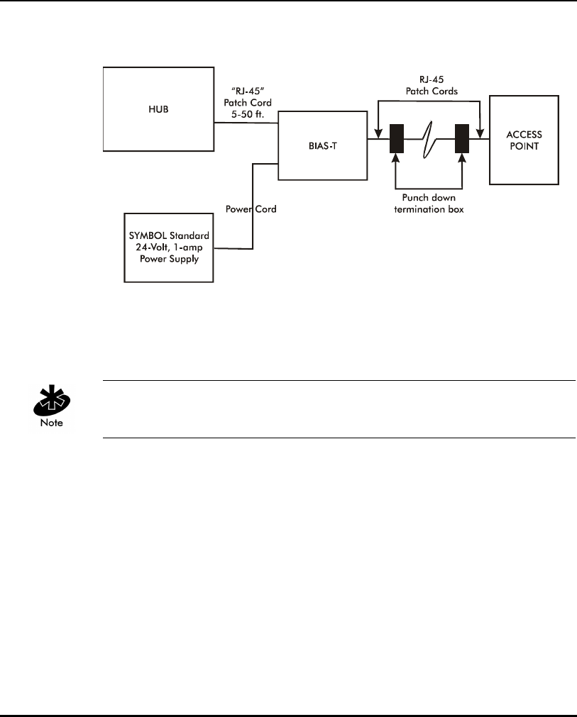
Hardware Installation
196 AP-4131 Access Point Product Reference Guide
To install a BIAS-T system using a single BIAS-T unit and access point:
Steps 1-3 could involve running Ethernet cabling through industrial walls or
ceilings. Only a qualified contractor should perform this kind of cabling.
1. Attach one end of a RJ-45 patch cord (5-50 ft.) to the access point. Run
the other end of the RJ-45 patch cord through a ceiling or wall into a
punch down termination box.
2. Run a CAT-5 Ethernet cable from the punch down termination box to
another punch down termination box in the wall or ceiling near the
intended location of the BIAS-T unit.
3. Secure a second RJ-45 (5-50 ft.) patch cord from the punch down
termination box to the output connector on the right-hand side of the
BIAS-T unit.

Hardware Installation
AP-4131 Access Point Product Reference Guide 197
4. Attach a third RJ-45 patch cord from the input connector on the left-hand
side of the BIAS-T unit to the HUB supporting the Spectrum24 component
installation.
5. Attach the cable supplied with the Symbol Standard 24-volt power supply
to the power-input connector on the left-hand side of the BIAS-T unit.
6. Repeat steps 1 through 5 for each additional BIAS-T unit and
Spectrum24 access point connected to the HUB as part of the same
Spectrum24 component installation.
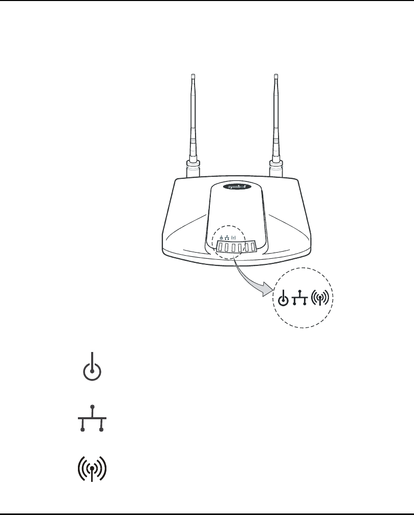
Hardware Installation
198 AP-4131 Access Point Product Reference Guide
4.9 LED Indicators
The top panel LED indicators provide a status display indicating transmission
and other activity. The indicators are:
Power Flashing indicates AP initialization.
Steady Green during operation.
Wired LAN Activity Flashing indicates data transfers on
wired connection.
Wireless LAN Activity Flickering indicates beacons and data
transfers with MUs.

Hardware Installation
AP-4131 Access Point Product Reference Guide 199
4.9.1 WLAP mode LED display.
When in the WLAP mode the chart below signifies the APs LED indicator
status.
For the IEEE 802.11 protocol and APs using firmware version 2.51-0X or
above only.
1. After power up, system initialization begins:
2. When a WLAP begins a full scan:
3. When one or more WLAPs are found, but still in full scan state:
4. When the WLAP is in functional state, but one or more WLAP connections
are not in Forward state:
LED State
Power On
Wired LAN Activity Off
Wireless LAN Activity Blinks slowly
LED State
Power On
Wired LAN Activity Off
Wireless LAN Activity Blinks slowly
LED State
Power On
Wired LAN Activity Off
Wireless LAN Activity Blinks slowly
LED State
Power Blinks regularly
Wired LAN Activity Blinks if activity occurs
Wireless LAN Activity Blinks slowly

Hardware Installation
200 AP-4131 Access Point Product Reference Guide
5. When all WLAP connections are in Forward state:
Special cases:
• If the WLAP manual BSS_ID is NOT set and no other WLAP is found,
the WLAP goes to the functional state.
• If the WLAP manual BSS_ID is set and the specified WLAP is not found,
the WLAP remains in FULL Scan state permanently. The LEDs have the
following indicator status permanently:
• If the WLAP manual BSS_ID is set with the broadcast bit ON (i.e. the first
Byte is 01) and the specified WLAP is not found, the WLAP tries to
associate with another WLAP. If it still cannot find another WLAP, it goes to
Functional State.
•If the Ethernet Timeout in the System Configuration menu is set to 3,
the WLAP will keep track of the WLAP Alive BPDU. If the BPDU is missing
for WLAP Hello Time seconds, the WLAP state changes to WLAP Lost on
Ethernet and the LEDs have the following states:
LED State
Power On
Wired LAN Activity Blinks if activity occurs
Wireless LAN Activity Blinks regularly
LED State
Power On
Wired LAN Activity Off
Wireless LAN Activity Blinks slowly
LED State
Power On
Wired LAN Activity Blinks slowly
Wireless LAN Activity Off

Hardware Installation
AP-4131 Access Point Product Reference Guide 201
4.10 Troubleshooting
Check the following symptoms and their possible causes before contacting
the Symbol Support Center.
4.10.1 Ensure wired network is operating
Verify AP operation:
1. AP does not power up:
– faulty AP power supply
–failed AC supply
–Electrical Management System (EMS) operating outlet.
2. After the AP resets and hardware is initialized, it performs an SRAM test.
If the test passes, the LEDs turn on. If the test fails, the LEDs all turn off
and the AP resets. The LEDs turn off sequentially as each test passes.
Identify wired network problems:
1. No operation:
– Verify AP configuration through Telnet or UI. Review procedures for
Ethernet and serial connection of the AP. Review AP firmware
revisions and update procedures.
– Verify network configuration by ensuring that there are no duplicate
IP addresses. Power down the device in question and ping the
assigned address of the device. Ensure no other device responds to
that address.
2. AP powered on but has no connection to the wired network:
– Check connections for proper wiring.
3. Verify network wiring and topology for proper configuration:
– Check that the cables used have proper pinouts and connectors.
– Verify router configuration and filtration setting.
– Verify MU operations.
– Confirm AP operation.
– Confirm AP and MU Net_ID (ESS).

Hardware Installation
202 AP-4131 Access Point Product Reference Guide
– Check that the radio driver loaded properly.
– Check that the MU PROTOCOL.INI or NET.CFG file is compatible
with the network operating system.
4. Slow or erratic performance:
– Check MU and RF communications range.
– Check antenna, connectors and cabling.
– Verify that antenna diversity setting for AP is appropriate. If using
one antenna, the setting is Primary Only, if using both antennas,
the setting is Full Diversity(in this setting the radio receives on the
primary or secondary antenna and transmits on the last antenna to
receive a signal) or Rx Diversity (in this setting the radio receives
on the primary or secondary antenna but transmits on the primary
antenna only).
– Verify network traffic does not exceed 37% of bandwidth.
– Check to see that the wired network does not exceed 10 broadcast
messages per second.
– Verify wired network topology and configuration.
4.11 Setting Up MUs
Refer to the LA-4100 Series PC Card & PCI Adapter Product Reference Guide
for installing drivers, client software and testing. Use the default values for
the Net_ID (ESS) and other configuration parameters until network
connection verification.
MUs attach to the network and interact with the AP transparently.

AP-4131 Access Point Product Reference Guide A-1
Appendix A Specifications
A.1 Physical Characteristics
Dimensions 1.75” H x 6” L x 8.5” W (4.45” cm H x 15.24” cm L x
21.59” cm W)
Weight
(w/power supply)
1 lbs. (0.454 kg)
Operating
Temperat ure
-4º F to 131º F (-20º C to 55º C)
Storage Temperature -40º F to 149º F (-40º C to 65º C)
Humidity 10% to 95% noncondensing
Shock 40 G, 11 ms, half-sine
ESD meets CE-Mark
Drop withstands up to a 30 in. (76 cm) drop to concrete
with possible surface marring

Specifications
A-2 AP-4131 Access Point Product Reference Guide
A.2 Radio Characteristics
Frequency Range (country dependent; within 2400 MHz to 2500 MHz)
Radio Data Rate • 11 Mbps -- Optional
• 5.5 Mbps -- Optional
• 2 Mbps -- Required
• 1 Mbps -- Required
11 Mbps Range open environment - over 100 ft. typical office or
retail environment - 30 to 50 ft.
TX Max. Radiated EIRP US: FCC part 15.247
Europe: ETS 300 320
Japan: RCR STD-33
Modulation Binary GFSK
TX Out-of-Band
Emissions
US: FCC part 15.247, 15.205, 15.209
Europe: ETS 300 320
Japan: RCR STD-33

Specifications
AP-4131 Access Point Product Reference Guide A-3
A.3 Network Characteristics
Driver Support NDIS v4.0 and v5.0
Ethernet Frame DIX, Ethernet_II and IEEE 802.3
Filtering Packet Rate 14,400 frames per second filtering and forwarding
Ethernet Connection 10/100Base-T (AP-4131 model access point only)
Serial PC/AT serial port - DB9 Male, RS-232 using a DTE
termination, 19200 bps
SNMP s24dsap.mib, MIB-II and 802.1x.mib

Specifications
A-4 AP-4131 Access Point Product Reference Guide

AP-4131 Access Point Product Reference Guide B-1
Appendix B Supported Modems
The AP uses Hayes commands and is capable of working with various
modems of 19200 baud or faster.
Symbol does not support modems the company has not qualified.
The following modems qualify to work with the AP-4131access point:
• US Robotics Faxmodem v.90.56K
• US Robotics Faxmodem v.33.6K
• US Robotics Faxmodem v.34 and v.32 bis Sportster 28.8K
• Diamond Supra Express 56K

Supported Modems
B-2 AP-4131 Access Point Product Reference Guide

AP-4131 Access Point Product Reference Guide C-1
Appendix C Customer Support
Symbol Technologies provides its customers with prompt and accurate
customer support. Use the Symbol Support Center as the primary contact for
any technical problem, question or support issue involving Symbol products.
If the Symbol Customer Support specialists cannot solve a problem,
access to all technical disciplines within Symbol becomes available for
further assistance and support. Symbol Customer Support responds to calls
by email, telephone or fax within the time limits set forth in individual
contractual agreements.
When contacting Symbol Customer Support, please provide the
following information:
• serial number of unit
• model number or product name
• software type and version number.
North American Contacts
Inside North America, contact Symbol by:
• Symbol Technologies, Inc.
One Symbol Plaza
Holtsville, New York 11742-1300
Telephone: 1-631-738-2400/1-800-SCAN 234
Fax: 1-631-738-5990
• Symbol Support Center:
– telephone: 1-800-653-5350
– fax: (631) 563-5410
– Email: support@symbol.com

Customer Support
C-2 AP-4131 Access Point Product Reference Guide
International Contacts
Outside North America, contact Symbol by:
•Symbol Technologies
Symbol Place
Winnersh Triangle, Berkshire, RG41 5TP
United Kingdom
0800-328-2424 (Inside UK)
+44 118 945 7529 (Outside UK)
Symbol Developer Program Web Site
http://software.symbol.com/devzone
Symbol Knowledge Base
http://kb.symbol.com/register.asp
Additional Information
Obtain additional information by contacting Symbol at:
• 1-800-722-6234, inside North America
• +1-631-738-5200, in/outside North America
•http://www.symbol.com/

AP-4131 Access Point Product Reference Guide D-1
Appendix D Country Identification Codes
Use the table below to select a Country Name, First Channel, Number (No.)
of Channels, Default Channel, Maximum Transmit Power, Regulatory
Domain, and Country ID. Update these values in the AP installation screen.
Contact a local representative for any country not listed.
Country Name Country ID Channels Max. Tx
Power (Dbm)
Regulatory
Domain
First No. Default
Argentina AR 113 11 30 99
Australia AU 113 11 20 99
Austria AT 113 11 20 30
Bahrain BH 113 320 99
Belarus BY 113 320 99
Belgium - Indoor BE 113 11 20 30
Belgium - Outdoor BE 1 1 13 20 30
Brazil BR 113 11 30 99
Bulgaria BG 113 320 30
Canada CA 113 327 20
Chile CL 113 11 17 99
China CN 113 320 99
Columbia CO 113 11 30 99
Costa Rica CR 113 320 99
Croatia HR 113 11 20 30
Czech Republic CZ 113 320 30
Denmark DK 113 11 20 30

Country Identification Codes
D-2 AP-4131 Access Point Product Reference Guide
Finland FL 113 11 20 30
France FR 11 311 20 32
Germany DE 113 11 20 30
Greece GR 113 11 20 30
Guatemala GT 113 320 99
Hong Kong HK 113 320 99
Hungary HU 113 320 30
Iceland IS 113 11 20 30
India IN 113 320 99
Indonesia ID 113 320 99
Ireland IE 113 11 20 30
Israel IL 5 4 6 20 99
Italy IT 113 11 20 30
Japan JP 114 11 20 40
Jordan JO 113 320 99
Kuwait KW 113 11 20 99
Liechtenstein LN 113 11 20 30
Lithuania LT 113 320 99
Luxembourg LU 113 11 20 30
Malaysia MY 113 320 99
Mexico MX 11 311 30 99
Morocco MA 113 320 99
Netherlands NL 113 11 20 30
New Zealand NZ 113 320 99
Norway NO 113 11 20 30
Peru PE 113 320 99
Country Name Country ID Channels Max. Tx
Power (Dbm)
Regulatory
Domain
First No. Default

Country Identification Codes
AP-4131 Access Point Product Reference Guide D-3
Panama PA 113 320 99
Philippines PH 113 320 99
Poland PL 113 320 99
Portugal PT 113 11 20 30
Qatar QA 113 320 99
Romania RO 113 320 99
Russian Federation RU 113 320 99
Saudi Arabia SA 113 320 99
Singapore SG 10 411 20 99
Slovak Republic SO 113 320 30
Slovenia SI 113 320 30
South Africa ZA 113 320 99
South Korea KR 113 11 20 99
Spain ES 113 11 20 31
Sri Lanka LK 1 2 1 20 99
Ta i wa n TW 113 327 20
Thailand TH 113 320 99
Turkey TR 113 320 99
UAE UE 113 320 99
Ukraine UA 113 320 99
UK UK 113 11 20 30
USA US 111 11 30 10
Venezuela VE 113 11 30 99
Country Name Country ID Channels Max. Tx
Power (Dbm)
Regulatory
Domain
First No. Default

Country Identification Codes
D-4 AP-4131 Access Point Product Reference Guide
A site license is required for India. To support this regulatory requirement,
enter the Site License ID in the Net_ID field on the AP Installation Screen.

AP-4131 Access Point Product Reference Guide E-1
Appendix E Installing and Configuring
Kerberos Setup Service
The Kerberos Setup Service (KSS) program runs on the Key Distribution
Center (KDC) server. The KSS can be used optionally to administer
Spectrum24 access points authorized on the network. For example, an AP on
the Access Control List (ACL) is lost or stolen. The KSS marks the AP (using the
MAC address of the AP) as not authorized and notifies the administrator if
the missing AP appears elsewhere on the network attempting authentication.
All clients (MUs), KDC and services (APs) participating in the Kerberos
authentication system are required to have their internal clocks synchronized
within a specified maximum amount of time (known as clock skew). The KSS
uses Network Time Protocol (NTP) or the system clock on the Kerberos server
to provide clock synchronization (timestamp) between the KDC and APs as
part of the authentication process. Clock synchronization is essential since
the expiration time is associated with each request for resources. If the clock
skew is exceeded between any of the participating hosts, requests are
rejected.
Additionally, the KSS provides a list of authorized APs and other security setup
information that the KDC uses to authenticate clients. When setting up the
KSS, assign APs an ESSID to authenticate with the KDC. In Open Enrollment
mode, the KSS dynamically creates an AP Setup Account for the AP and
creates a Kerberos account with the KDC. The KSS continues to do this until
the administrator disables Open Enrollment.
For additional information on KSS and KDC functionality, refer to the sections
of this document.
E.1 Creating a Windows 2000 Environment for the KSS
The KSS runs only on a Windows 2000 server with Active Directory enabled
and Java Runtime Environment version 1.3 (or higher) running.

Installing and Configuring Kerberos Setup Service
E-2 AP-4131 Access Point Product Reference Guide
Java Runtime is on the Spectrum24 High Rate 11 Mbps Wireless LAN
Software CDROM within the KSS directory.
For information on installing Windows 2000 Server, setting up the KDC and
enabling ActiveDirectory services, refer to the documentation shipped with
Windows 2000 server.
E.2 Installing the KSS in a Windows 2000 Environment
Install the KSS from the Spectrum24 High Rate 11 Mbps Wireless LAN
Software CDROM or go to the Symbol Website
(http://www.symbol.com/services/downloads/download_spec24.html).
If internet access is unavailable, contact a sales representative for a CD.
Once downloaded, extract the files to the computer hard drive.
Java Runtime is required on the Windows 2000 server before the KSS is
installed. Java Runtime is on the Spectrum24 High Rate 11 Mbps Wireless
LAN Software CDROM within the KSS directory.
1. Insert the Spectrum24 High Rate 11 Mbps Wireless LAN Software
CDROM (optional) if it is being used in the installation.
2. Specify the location of the KSS install folder.
The KSS files either reside on the CDROM or computer hard drive if they
were downloaded from the Symbol Website.
3. Double-click Setup.exe from the KSS Install folder.
The KSS Welcome screen displays. Click Next.
4. When the Software License Agreement screen displays click Yes (if
accepting all the terms of the license agreement) or No to exit and
cancel the KSS installation.
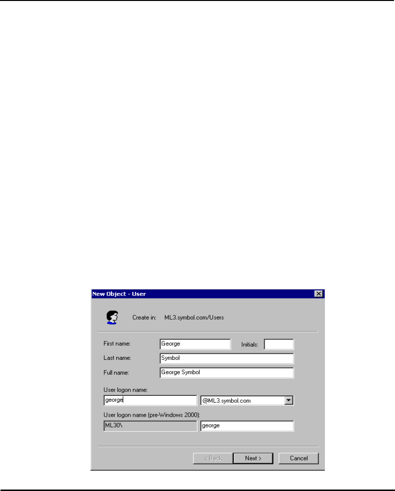
Installing and Configuring Kerberos Setup Service
AP-4131 Access Point Product Reference Guide E-3
5. Click Next when the Choose Destination Location dialog box displays
to install KSS to the default destination folder.
The user has the option of clicking Browse and selecting a different
folder if necessary.
A progress bar displays showing the progress of the KSS files installation.
6. The Setup Complete dialog box displays stating it has finished installing
KSS. Clear the Yes I want view the Read Me file now checkbox or leave
it selected to view the Read Me file.
7. Click Finish to complete the installation.
E.2.1 Creating a User Account and Password in Active Directory
Before configuring the KSS, create a user account on the KDC with domain
administration privileges. This account allows the KSS to interface with Active
Directory to enable KSS configuration.
To create a user account and password in active directory:
1. Select Users from the Active Directory window.
2. Right-click and select New. Select User.
The New Object - User dialog box displays.
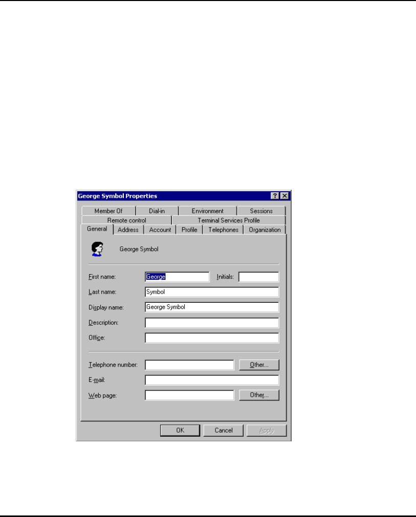
Installing and Configuring Kerberos Setup Service
E-4 AP-4131 Access Point Product Reference Guide
3. Enter the user name (20 characters maximum) in the First name and
Last name fields. Click Next.
4. Enter and confirm a password for the user.
5. Select the Password never expires checkbox and click Next.
A confirmation dialog box displays. Click Finish.
6. Right-click the newly created user account from the Active Directory
window. Select Properties.
7. Select the Members Of tab and click Add.
8. Select Domain Admins and click Add. Click OK.
9. Select the Account tab. A Properties dialog box displays for the user.
10. Select the Use DES encryption types for this account and Do not
require Kerberos preauthentication checkboxes.
11. Click OK.
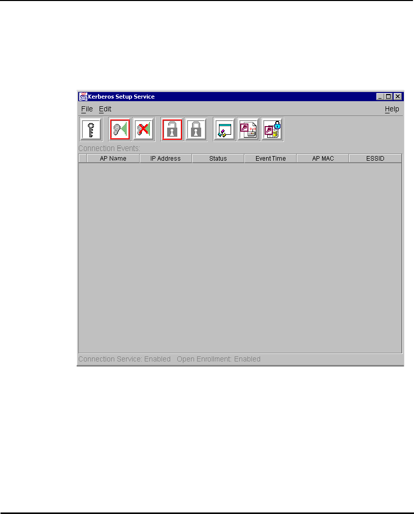
Installing and Configuring Kerberos Setup Service
AP-4131 Access Point Product Reference Guide E-5
E.3 Preparing the KSS for Access Point Validation
To prepare the KSS to validate access points:
1. Click Start select Programs, WLAN, WLAN KSS, and Start KSS.
The Kerberos Setup Service dialog box displays.
2. Using the user account created in the previous section, select Admin Info
from the File menu or click the Key icon from the top left-hand corner of
the Kerberos Setup Service dialog box. Enter Admin info and password
information.
3. Click OK to continue.
4. Select the Preference icon (third icon from the right) from the Kerberos
Setup Service dialog box.
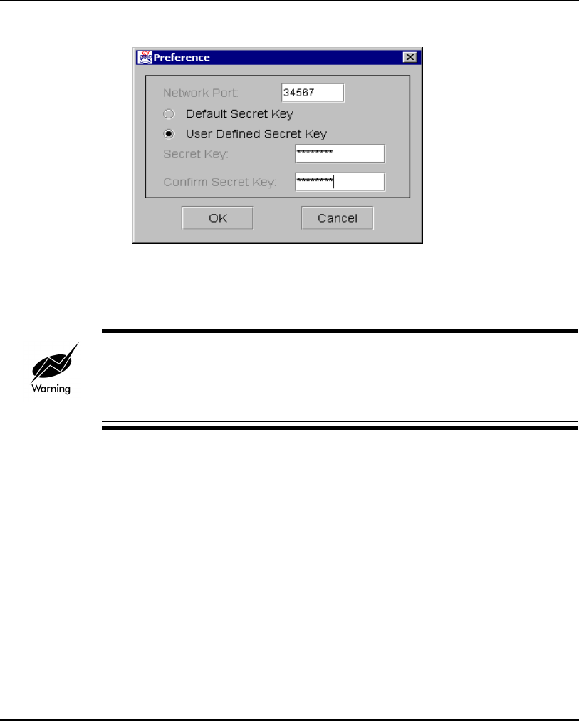
Installing and Configuring Kerberos Setup Service
E-6 AP-4131 Access Point Product Reference Guide
The Preference dialog box displays.
5. Select User Defined Secret Key to enter and confirm a secret key
different from the default key. If the default secret key is acceptable,
leave the Default Secret Key checkbox selected.
The same secret key entered in the Preference dialog box is required in the
KSS Secret field of the access point Configure Kerberos Authentication
screen.
The Network Port default setting is 34567. Modify the setting if device
conflicts occur.
6. Click OK to continue.
7. From the Edit pull-down menu select Kerberos Account or click the
Kerberos Account Options icon on the top right-hand side of the
Kerberos Setup Service dialog box.

Installing and Configuring Kerberos Setup Service
AP-4131 Access Point Product Reference Guide E-7
The Kerberos Account Entry dialog box displays.
8. Select the Edit Open Enrollment Default Properties checkbox.
9. Enter the KDC Name, Realm/Domain and KDC IP Address values.
Do not set an ESSID or create a Password at this time.
The ESSID/Principal and Password are sent from the AP, during Open
Enrollment. APs with the same ESSID share common Kerberos account
information. The ESSID is the Kerberos Principal for APs.
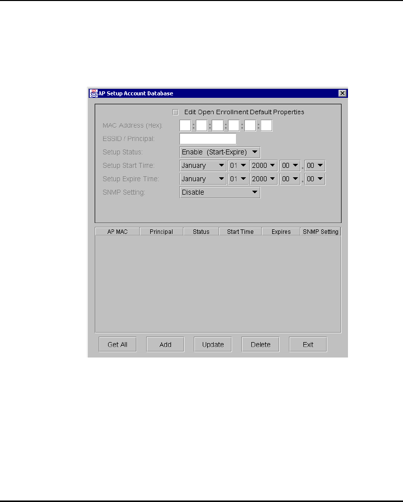
Installing and Configuring Kerberos Setup Service
E-8 AP-4131 Access Point Product Reference Guide
10. Click Save.
The Kerberos Account Entry property page displays the new values.
11. Click Exit to return to the Kerberos Setup Service window.
12. Click the AP ACL icon (second icon from the top right-hand side).
The AP Setup Account Database dialog box displays. Select the Edit
Open Enrollment Default Properties checkbox.
If required, select Enable (Read/Write) from the SNMP Setting field.
If the Edit Open Enrollment Default Properties checkbox is not selected
the user has the ability to restrict KSS authentication for the single access
point displayed in the MAC Address (Hex) field.
Use the Setup Status, Setup Start Time and Setup Expire Time pull
down menus to specify the time period the selected access point is
allowed to authenticate with the KSS.
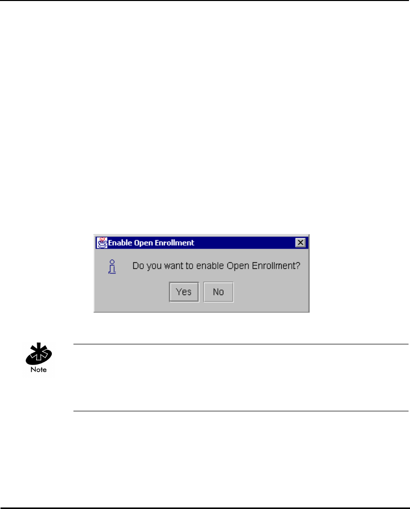
Installing and Configuring Kerberos Setup Service
AP-4131 Access Point Product Reference Guide E-9
Selecting Enable (Always) from the Setup Status pull-down menu
enables KSS authentication for the selected access point at all times.
Selecting Enable (Start-Expire) from the Setup Status pull-down menu
enables KSS authentication for the selected access point only during the
time period specified within the Setup Start Time and Setup Expire Time
pull-down menus.
Selecting Disable prohibits the selected access point from authenticating
with the KSS.
13. Click Save.
The AP Setup Account Database property page displays the new
settings. Click Exit to return to the Kerberos Setup Service window.
14. From the File menu, select Enable Open Enrollment or click on the
Enable Open Enrollment icon to enable the KSS to discover Kerberos
enabled access points on the network.
The Enable Open Enrollment info box appears
15. Click Yes.
If Yes is selected, the KSS tests the configuration parameters by creating a test
account on the KDC. If the test is successful, the test account is deleted and a
dialog box displays notifying the user that Open Enrollment is now enabled.
If the test fails, check the Admin info or default Open Enrollment values.
16. From the File pull-down menu, select Listen or click on the Listen icon.
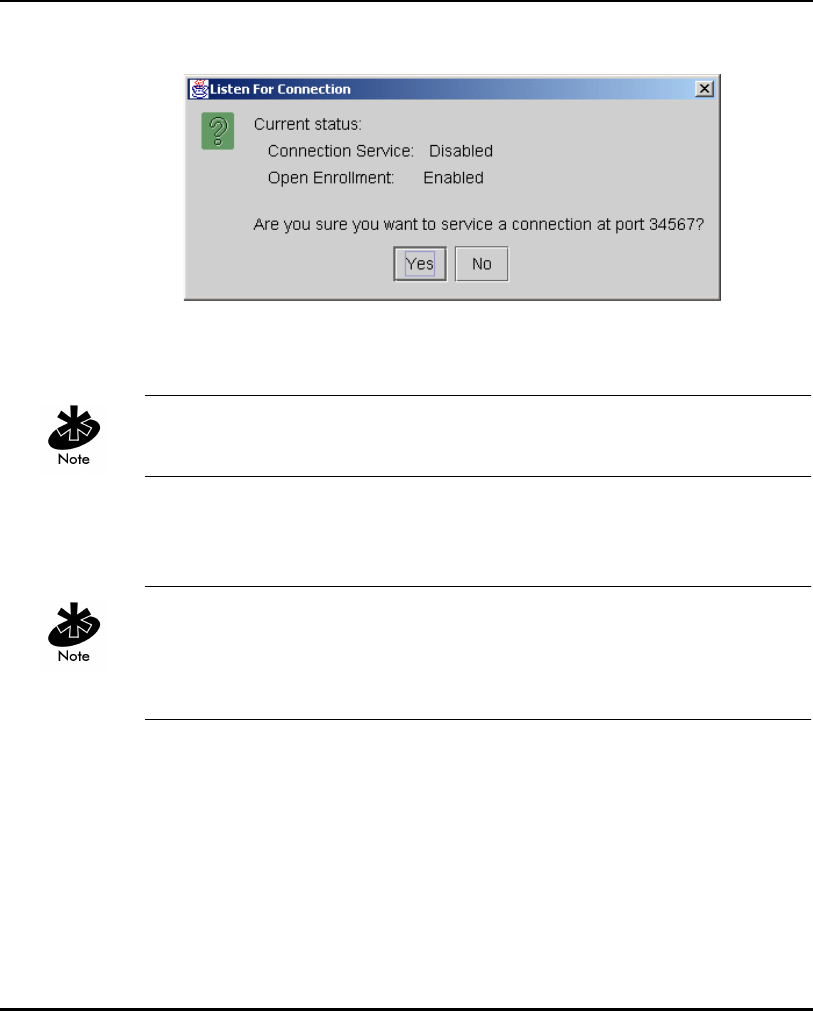
Installing and Configuring Kerberos Setup Service
E-10 AP-4131 Access Point Product Reference Guide
The Listen For Connection Box displays.
17. Select Yes if this is the correct connection port.
The Kerberos Setup Service window displays.
The next step is to configure the access points for Kerberos support if they
have not already been configured.
18. Reboot the access points. Refer to the AP-4131 Access Point Product
Reference Guide for Kerberos setup information.
The connection port is required to match the AP connection port. Refer to the
Manual Kerberos Authentication Configuration section of this document
for additional information. The Listener Port is required to remain open for
the access point to receive network time every eight hours.
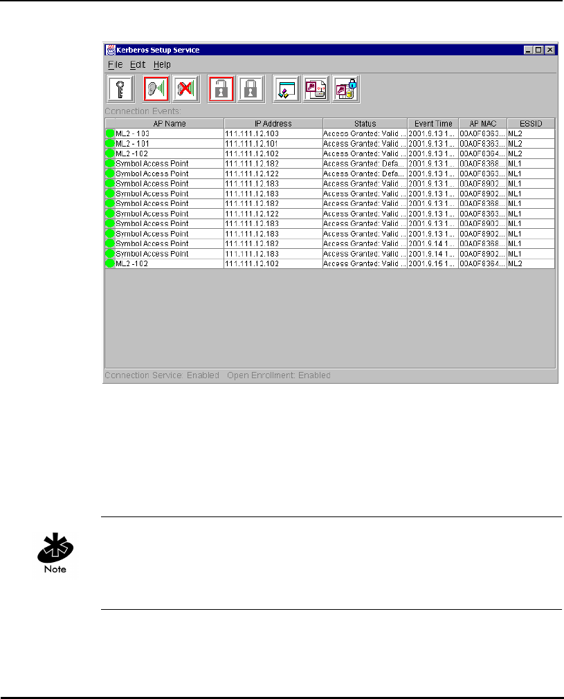
Installing and Configuring Kerberos Setup Service
AP-4131 Access Point Product Reference Guide E-11
When the APs initialize, the AP list view window displays the Connection
Events (APs that were either successful or were not granted access to
KSS).
19. When the access points have successfully initialized, select Disable Open
Enrollment from the File pull-down menu or click on the Locked Padlock
icon once the access points have been granted access.
Disable Open Enrollment to prevent foreign access points from getting
information from the KSS. Only APs that were successful gaining access to
the KSS during Open Enrollment are given Kerberos authentication
information after it is disabled.

Installing and Configuring Kerberos Setup Service
E-12 AP-4131 Access Point Product Reference Guide
E.4 Manually Creating an Access Point Setup Account
Manually create an AP Setup Account for the AP and create a Kerberos
account with the KDC. The AP Setup Account database stores validation
information for an AP.
Manually create an access point setup account only if the user does not want
to use the Open Enrollment option.
When Open Enrollment is disabled and an access point is manually added
to a Kerberos account entry, enter the ESSID, Password, KDC Name, Realm/
Domain and KDC IP Address values. The ESSID and password are required
to match the AP Kerberos configuration. If either value is incorrect the AP
cannot communicate with the KSS (no error messages are displayed).
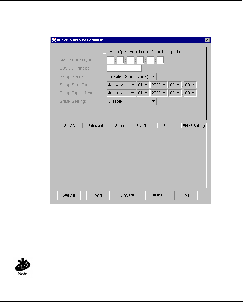
Installing and Configuring Kerberos Setup Service
AP-4131 Access Point Product Reference Guide E-13
To create an access point setup account:
1. From the Edit menu, select AP Setup ACL.
2. Enter the AP MAC Address as a Primary Key in the AP Setup Account
Database dialog box.
3. Enter the ESSID. The ESSID is used as the Kerberos Principal for the AP.
The AP Setup Account is used to control which access points are
permitted Kerberos Setup information.
Kerberos restrictions prohibit the length of the ESSID from exceeding 20
characters. Only alphabetic and numeric characters are allowed.

Installing and Configuring Kerberos Setup Service
E-14 AP-4131 Access Point Product Reference Guide
4. Enter the AP access range set the time and status information using the
Setup Start Time and Setup Expire Time pull-down menus.
5. Set the SNMP Setting.
6. Click Add when all the parameters have been entered.
After the AP initializes, the AP list view window displays the Connection
Events (APs successful in gaining access to KSS).
E.5 Implementing Kerberos without the KSS
Kerberos support is available for the AP-4131 access point without the use of
the KSS. This configuration requires Windows 2000 Server with SP2.
To configure Kerberos support without the KSS:
1. Install Active Directory, making the server a domain controller (preferably
a Primary Domain Controller).
Configuring an Additional Domain Controller requires the presence of a
PDC and synchronization of the user database. Choose defaults for
Domain Controller configuration if it is a PDC. Record the Domain name
as it would be needed for configuring the AP.
2. Enable DNS if no other DNS server is available on the network.
3. Enable network time services (Daytime or SNTP) on this server or another
networked server. The same server as the KDC server can be used.
From the Windows Control Panel, click Add/Remove Programs. Click
Add/Remove Windows Components, double-click Networking
Services, and select Simple TCP/IP Services. Click OK and Next. The
Win2k Server CD is required to add this component.
4. Create user accounts for the access points and Kerberos Clients. The
username for the access point user account should be the same as the
access point ESSID. Therefore, only one AP user account for each WLAN
(or ESSID) is required.
5. After creating each account, right-click on an account and click
properties. Click the Account tab. Select Do not require Kerberos
Pre-Authentication.

Installing and Configuring Kerberos Setup Service
AP-4131 Access Point Product Reference Guide E-15
The access point can now be configured for Kerberos support via the
Serial or Telnet interfaces.
The Kerberos Configuration parameters have been moved to the Special
Functions screen in the Serial and Telnet UI.
6. From the Configure Kerberos screen set Kerberos to Enabled.
7. Set the KDC Server Name/IP to the IP Address where the KDC is setup.
8. (Optional) Set the Backup KDC Name/IP to the Name or the IP Address
of the backup or redundant KDC (if any).
9. Set the Realm Name to the Domain Name of the Win2k Server used as
the KDC.
10. Set the User ID and Password fields exactly the same as the Username
and Password set in Active Directory for the AP user account.
It is recommended that all APs have the same username and password so
the same configuration steps apply to all APs and only one account in Active
Directory is needed.
Network time can be obtained from a time server (SNTP or Daytime) other
than the same Win2k Server where the KDC resides. In the Network Time
screen, enter the IP address of the time server in the Time Server field.

Installing and Configuring Kerberos Setup Service
E-16 AP-4131 Access Point Product Reference Guide

AP-4131 Access Point Product Reference Guide Index-1
Numerics
10/100Base-T unshielded twisted pair 190
10/100Base-T UTP 190
A
access control 14
disallowed address 14
MU 14
unauthorized access 14
Access Control List 14
Access Point 1
access control 162
Access Control List 1
adding allowed MUs 115
adding disallowed MUs 119
advanced radio theory 12
analyzing retries 185
antenna selection 160
ARP request packet 13
ARP response packet 13
Basic Service Set 8
BSS_ID 8
CAM 24
cell 8
cellular coverage 8
Characteristics A-1
chipping sequence 18
clear statistics 187
clearing MUs 121
clearing statistics 187
configure 22
country code 160
data encryption 2
decryption 25
dial-up access 36
direct-sequence 19
disallowed address 14
encryption 25
Ethernet device 3
Ethernet statistics 174
Ethernet traffic 1
Ethernet wired LANs 1
event history 186
features 2
filtering 14
firmware version 162
foreign agent 165, 170
forwarding counts 164
hardware installation 189
hardware version 162
home agent 170
IEEE 802.11 8
interface 163
interface statistics 163
Introduction 1
known APs 171
LED indicators 198
MAC address 13
management options 34
manually updating the firmware 139
media types 16
miscellaneous statistics 182
Mobile IP 22
model number 162
Index

Index-2 AP-4131 Access Point Product Reference Guide
monitoring statistics 159
mounting 193
network connection 190
power adapter 193
power options 192
PSP 24
Radio Characteristics A-2
radio performance statistics 176
removing allowed MUs 115
RF statistics 176
roaming across routers 22
RSSI 21
shared key authentication 26
single-cell connection 191
site survey 11
site topography 11
SNMP management 34
Supported Modems B-1
system password 51
system summary 159
TCP/IP 41
Telnet 37
topologies 4
troubleshooting 201
type filtering option 14
UI 36
Web browser 41
wired network 201
WNMP statistics 183
ACL 113
adding allowed MUs 115
configuring 113
disallowed address 14
filtering 14
load ACL from MU list 116
options 116
removing allowed MUs 115, 116
removing disallowed MUs
unauthorized access 14
address filtering 118
configuration 120
disallowed addresses 118
MAC addresses 118
remove MUs 119
removing disallowed MUs 119
advanced radio theory 12
MAC layer bridging 12
analyzing retries 185
antenna
site survey 190
antenna placement 191
AP 63
adding filter types 120
Bridge Protocol Data Unit 10
configuration 129
DTIM 10
IEEE 802.11d Spanning Tree support 11
manually updating configuration 129
radio parameters 8
removing allowed MUs 116
removing disallowed MUs 119
removing filter types 120
repeater 7
TIM 10
type filtering 120
updating using Xmodem 132
wireless operation parameters 80
WLAP mode 6, 7, 10, 81, 162
WLAP mode LED display 199
WLAP priority value 10
WNMP function 8
AP installation 54

AP-4131 Access Point Product Reference Guide Index-3
additional DNS 57
additional gateways 56, 58
antenna selection 57
country config 56
dhcp disabled 58
dhcp/bootp enabled 58
dhcp/bootp options 58
DNS IP address 57
enable bootp only 58
enable only dhcp 58
gateway IP address 56
IP address 56
Net_ID (ESS) 57
subnet mask 57
unit name 56
AP-AP State Xchg 63
association process 19
beacon 24
Bridge Protocol Data Unit 10
CCA 20
direct-sequence systems 18
DTIM 10, 24
IEEE 802.1d Spanning Tree support 11
MU 19
MU ACK 20
roaming 19
root AP 10
RSSI 21
scanning 20
TIM 10
WLAP mode 10
WLAP priority value 10
auto fallback to wireless mode
introduction 14
B
Basic Service Set 8
BC/MC Q configuration 72
beacon 24
CAM stations 24
PSP stations 24
TIM 25
BOOTP 15
bridge
WLAP mode 6, 7, 81
broadcast ESS ID 73
BSS_ID 8
C
carrier signal 3
configuration 37
ACL 113
address filtering 118
BC/MC Q 72
beacon interval 73
broadcast ESSID 73
data transmission rate 74
dial-up connection 40, 53
DTIM packet frequency 72
Encryption Key Maintenance 88
manually updating AP firmware 139
manually updating configuration 129
manually updating using TFTP 129
maximum retries 72
Mobile IP 170
MU 73
multicast mask (data) 72
multicast mask (voice) 72
radio parameters 8, 71
resetting 157
restoring 157

Index-4 AP-4131 Access Point Product Reference Guide
saving 156
Setting Logging Options 137
Special Functions 156
system parameters 59
System Password Administration 69
TCP/IP 37
Telnet 37
type filtering 120
UI 37
updating using Xmodem 132
wireless operation parameters 80
WLAP forward delay 77, 84
WLAP hello time 76, 83
WLAP manual BSS ID 76, 83
WLAP Max Age 76, 83
WLAP mode 75, 82
WLAP priority 82
configuring ACL 113
range of MUs 113
removing allowed MUs 115, 116
configuring the SNMP agent 102
access cntrl violation 104
all traps 104
authentication failure 104
cold boot 104
DHCP change 105
kerberos errors 106
radio restart 104
read/write community 104
read-only community 99, 104
SNMP agent mode 99, 104
trap host1 IP address 104
trap host2 IP address 104
WLAP connection change 106
connecting power adapter 193
coverage area 9
AP 9
Basic Service Set 8
BSS_ID 8
cell 9
MU 9
WLAP mode 7
customer support C-1
additional information C-2
international contacts C-2
North American contacts C-1
D
data decryption 25
types of authentication 26
WEP algorithm 25
data encryption 25
AP 26
types of authentication 26
WEP algorithm 25
Delivery Traffic Indicator Map. See DTIM
DHCP support 15
acl file 16
configuration file 16
essid 16
firmware and html file 16
kdc name 16
kerberos enable 16
kss name 16
kss port number 16
digital data 3
direct sequence spread spectrum 3
disallowed address 14
access control 14
ACL 14
AP 14
disallowed MUs 119
removal 119

AP-4131 Access Point Product Reference Guide Index-5
DTIM
AP 10
association process 10
root AP 10
E
electromagnetic waves 3
encryption 25
128 Bit 92
40 Bit 90
administration 66
environment 3
ESSID 73
Ethernet interface 16
ethernet statistics 174
Ethernet wired LAN 1
F
features 2
10/100baseT Ethernet port interface 2
BOOTP support 2
built-in diagnostics 2
built-in dual antenna assembly 2
DHCP support 2
DNS support 2
increased MIB support 2
PC/AT serial port interface 2
power supply IEC connector 2
short RF preamble 2
SNMP support 2
upgradable firmware 2
Web browser user interface 2
wireless AP 2
wireless MAC interface 2
filtering
ACL 14
introduction 14
firmware 139
auto upgrade all APs via messaging 148
manually updating 139
update using TFTP 139
updating using Xmodem 143
firmware version 162
frequency range 3
G
gigahertz 1
H
hardware installation 189
antenna coverage 191
mounting the AP 193
network connection 190
package contents 189
power adapter 193
power options 192
precautions 189
single-cell connection 191
site survey 190
Help file
network Web server 42
I
ICMP 152
IEEE 802.1d Spanning Tree support
association process 11
LAN 11
IEEE address 3
MAC 3
IP forwarding address 22
roaming across routers 22
IP Address 165
AP 165
MU 165

Index-6 AP-4131 Access Point Product Reference Guide
K
Kerberos
AP proxy 29
authentication 26
authentication service (AS) 28
default setting 31
disabling 31
enabling 31
implementation 26
Key Distribution Center (KDC) 27
kss function 28, E-1
manual authentication configuration 94
MU authentication 29
realm 27
TGS_REP 29
TGS_REQ 29
Ticket Granting Ticket Server 28
known APs 171
MAC and IP addresses 171
statistics 171
KSS
databases 32
disable open enrollment 31
enable open enrollment 31
open enrollment period 31
L
LAN
IEEE 802.1d Spanning Tree support 11
LED indicators 198
description 198
flashing all LEDs 160
special cases 199, 200
WLAP mode LED display 199
M
MAC Layer Bridging 13
address database 13
MAC address 13
management options 34
SNMP 34
Telnet 34
WLAN 34
manually updating configuration
kerberos 94
using TFTP 129
Media Access Control 8
miscellaneous statistics 182
Mobile IP 21
configuration 156
foreign agent 22, 170
mapping 170
roaming across routers 22
using MD5 authentication 155
mobile unit (MU)
ESS 8
Model Number 162
monitoring statistics 159
ethernet statistics 174
interface statistics 163
miscellaneous statistics 182
radio statistics 176
MU 8
access control 14
ACL 14
association process 23
authentication 26
CAM 24
cellular coverage 8
clearing MUs from the AP 121
current transmit rate 168

AP-4131 Access Point Product Reference Guide Index-7
data encryption 25
DTIM 25
filtering 14
home agent 23
known APs 171
Mobile IP 21, 170
performing pings 152
power mode 168
priority 168
removing allowed MUs 116
scanning 23
security 25
statistics 165
supported rates 168
MU association process
19
multiple APs 5
N
network topology 3
P
programmable SNMP trap 34
management stations 34
MIB 34
SNMP agent 34
PSP stations 24
beacon 24
MU 24
R
radio basics 3
center frequency 3
digital data 3
electromagnetic waves 3
environment 3
ethernet device 3
IEEE address 3
MAC 3
radio links 3
receiving antenna 3
wireless network 4
radio interface 16
radio parameters 71
AP 8, 71
BC/MC Q maximum 72
beacon interval 73
broadcast ESS 73
configuration 8
configure 71
data transmission rate 74
DTIM interval 72
max retries (data) 72
max retries (voice) 72
multicast mask 72
RTS threshold 74
Short RF Preamble 77
Tx Power Control 77
WLAP MU table aging time 77, 84
radio performance statistics 177
packets reassembled 178
packets received 177
packets transmitted 177
retries 177
radio statistics 176
AP 176
viewing 176
rate control 74
repeater
AP 7
coverage area 7
WLAP mode 7

Index-8 AP-4131 Access Point Product Reference Guide
roaming across routers 22
AP 23
home agent 23
IP address 22
Mobile IP 21
MU 23
TIM 24
root AP
association process 10
Bridge Protocol Data Unit 10
DTIM 10
TIM 10
WLAP mode 10
S
security 25
decryption 25
encryption 25
kdc name 96
kerberos 96
kss name 96
kss port 96
realm name 96
user id 96
WEP algorithm 25
site survey 11
antenna coverage 191
AP 191
floor plan 12
hardware installation 189
site topography 11
AP 11
MU 11
signal loss 11
SNMP 34
configurtion 34
manager 34
support 35
trap 34
Spectrum24 1
introduction 1
management options 34
network topologies 3
radio basics 3
regulatory requirements 2
wireless network 1
spread spectrum
2.4GHz 1
2.5GHz 1
statistics 159
ethernet 174
filter 183
forwarding counts 164
interface statistics 163
IP address 173
known APs 171
Mobile IP 170
RF Statistics 176
SNMP 183
WNMP 183
system parameters 59
access control 63
Admin Password 70
AP-AP State Xchg 63
auto channel select 60
configuration 60
default interface 65
Encryption Admin 62
ethernet interface 65
Ethernet timeout 61
Inactivity Timeout 63
kdc name 96

AP-4131 Access Point Product Reference Guide Index-9
kerberos 96
kss name 96
kss port 96
MD5 key 62
Modem Connected 63
MU-MU Disallowed 63
password 96
realm name 96
rf Interface 65
S24 Mobile IP 62
System Password Admin 64
Telnet logins 60, 61
type filtering 63
user id 96
user password 70
WNMP functions 63
system password 47
system summary 159
access control 162
antenna selection 160
country code 160
current MUs 162
firmware version 162
IP address 158, 160
MAC address 158, 160
model number 162
Net_ID 160
serial number 162
WLAP mode 162
T
TIM
association process 10
root AP 10
Traffic Indicator Message. See TIM
transmission medium 3
troubleshooting 201
AP does not power up 201
no connection 201
slow or erratic performance 202
SRAM test 201
wired network operation 201
wired network problems 201
type filtering
adding filter types 120
configuration 120
removing filter types 120
U
UI 37
access 37
changing access 51
configuration 37
dial-up access 36
direct serial access 36
navigation 48
password 38
Telnet 36
Usage 36
Web browser 36
W
Web browser 41
WEP algorithm 25
wireless operation 75
wireless operation parameters
configuration 80
IEEE 802.1d Spanning Tree Protocol 80
WLAP forward delay 77, 84
WLAP hello time 75, 76, 83
WLAP interfaces 80
WLAP manual BSS ID 75, 76, 83

Index-10 AP-4131 Access Point Product Reference Guide
WLAP Max Age 75, 76, 83
WLAP mode 75, 82
WLAP priority 75, 82
WLAP
priority value 10
WLAP forward delay
configuration 77, 84
WLAP hello time
configuration 76, 83
WLAP manual BSS ID
configuration 76, 83
WLAP Max Age
configuration 76, 83
WLAP mode
AP 6, 7, 81
association process 10
bridge 6, 7, 81
configuration 75, 82
repeater 7
root AP 10
system summary 162
WLAP mode LED display
special cases 200
WLAP priority
configuration 82
WNMP function
AP 8
X
Xmodem 143
updating configuration 132
