Symbol Technologies VRC697C Wireless mobile computer terminal User Manual VRC 6940 Product Reference Guide
Symbol Technologies Inc Wireless mobile computer terminal VRC 6940 Product Reference Guide
Contents
- 1. Product Reference Guide
- 2. Quick Reference Guide
- 3. QRG Addendum
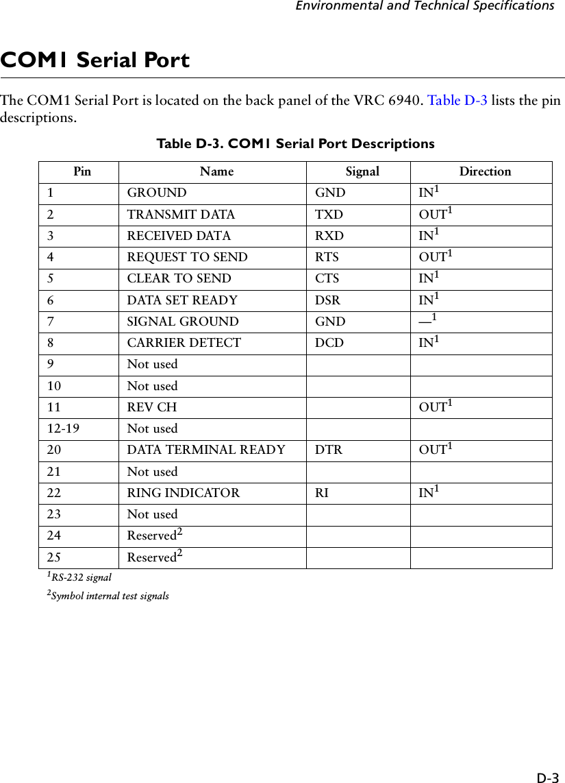
Product Reference Guide


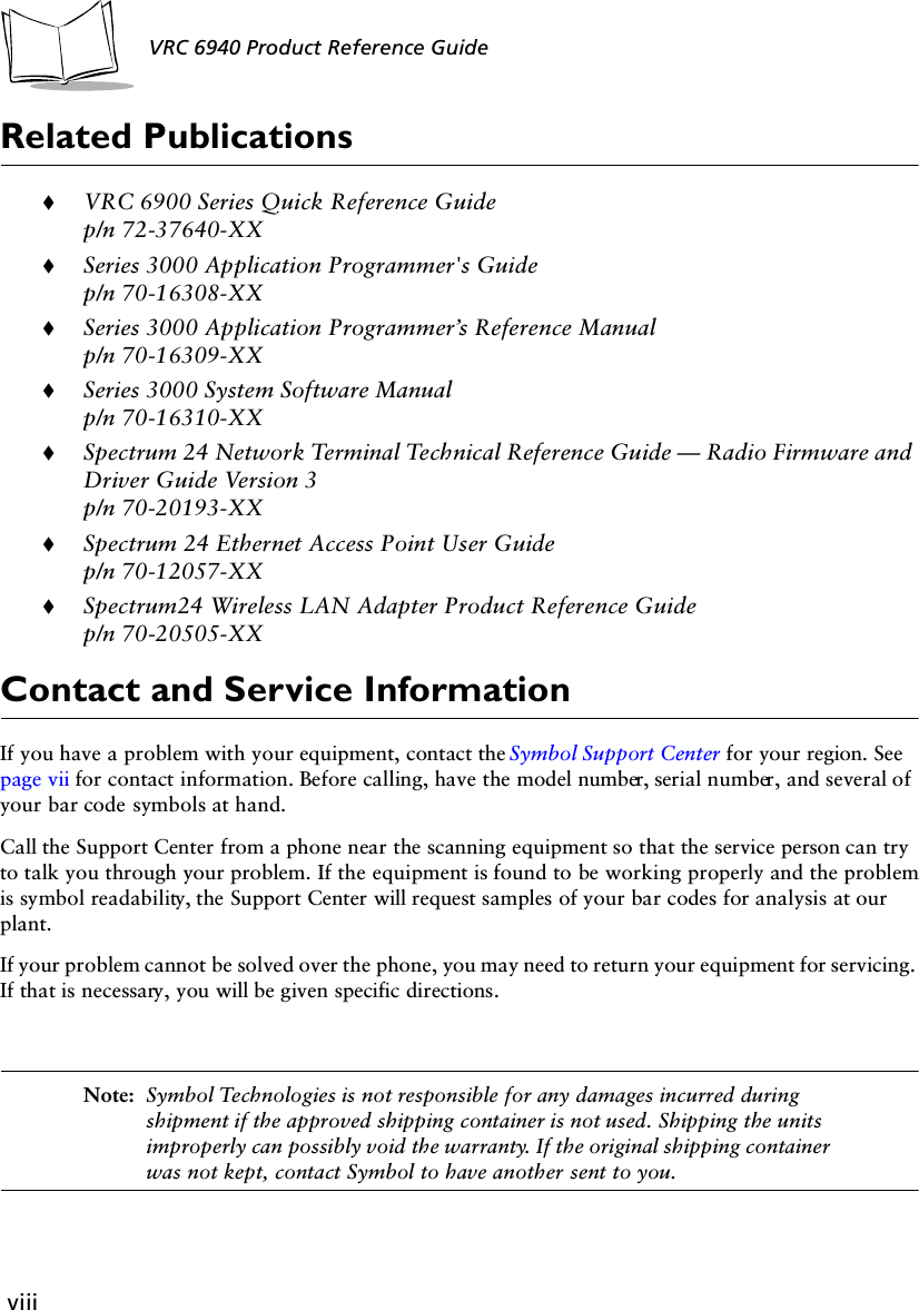

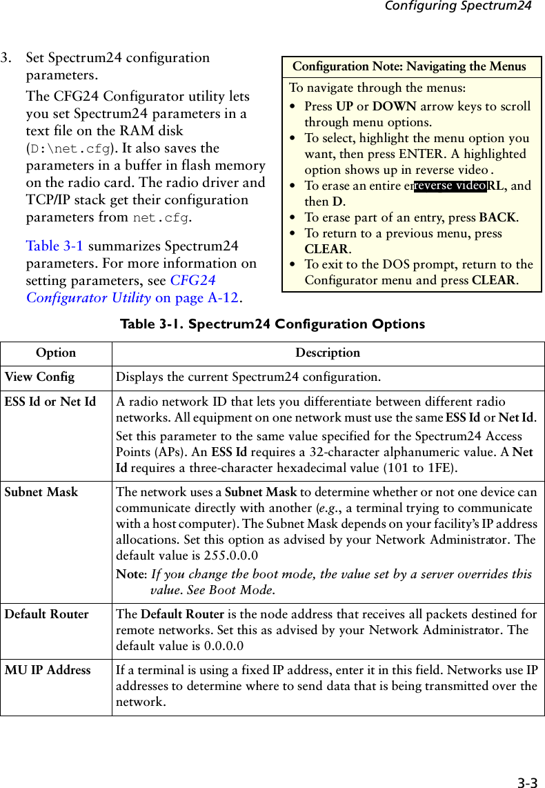

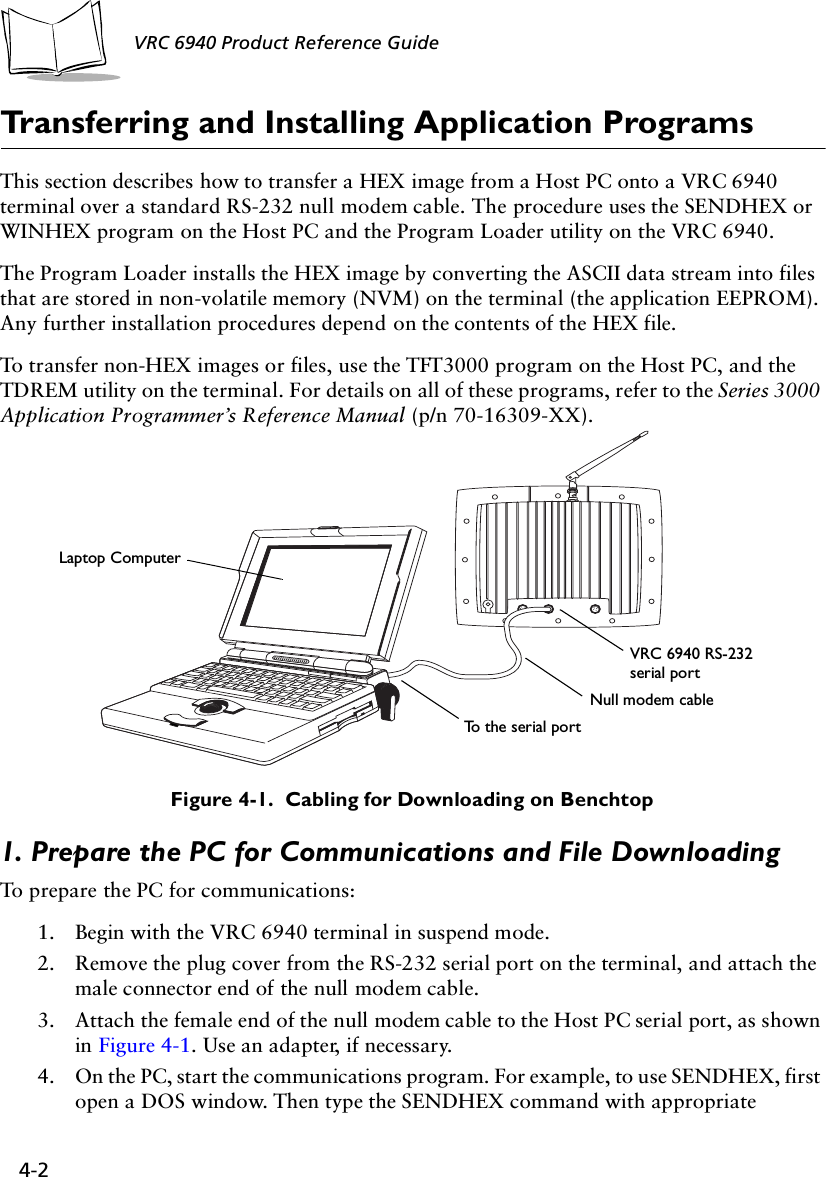
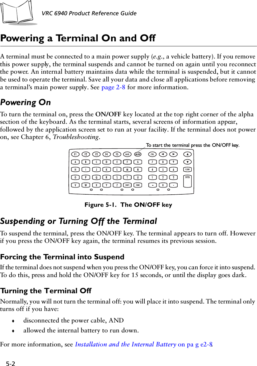
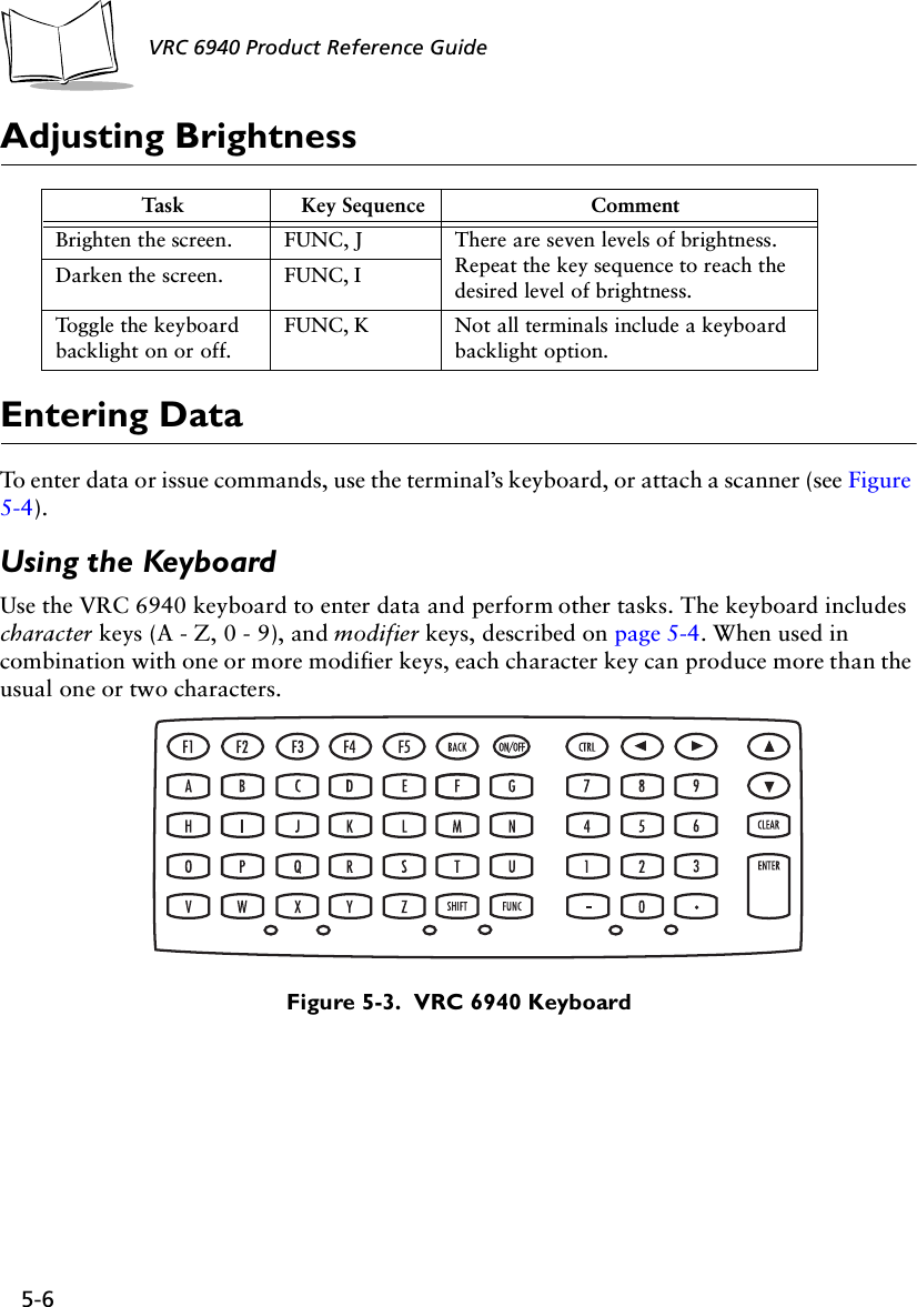
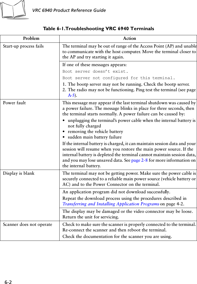
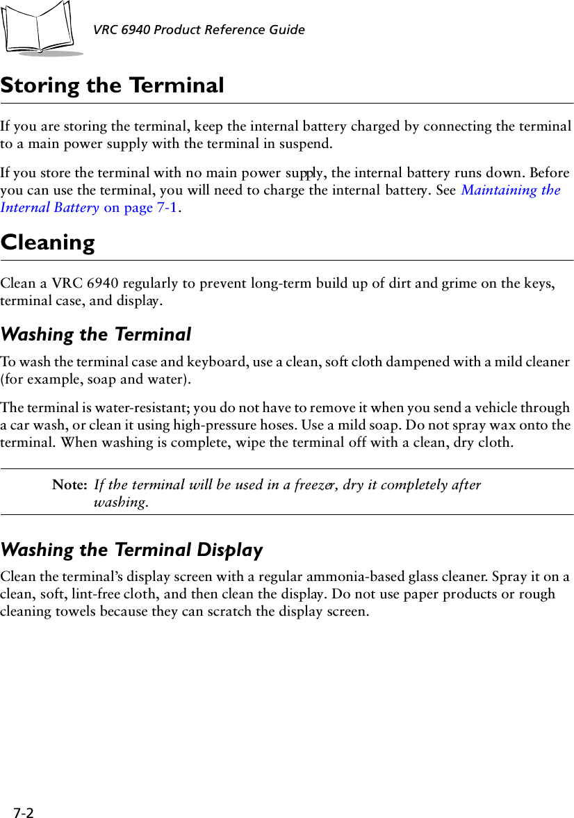
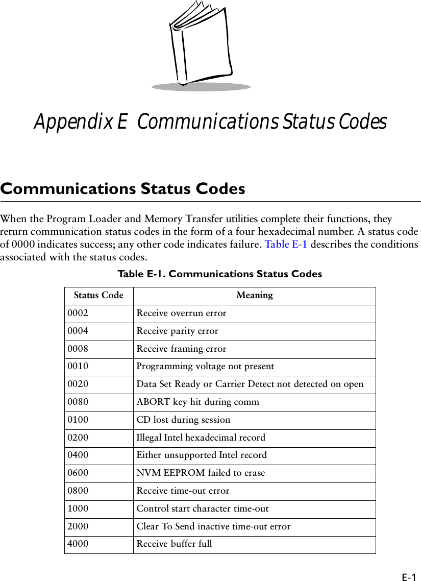
![A-5Utilities and Diagnostic TestsDIAG24 Diagnostics UtilityThe DIAG24 Diagnostics utility lets you ping an Access Point (AP) on the network as a way to identify possible problems with wireless network communication. DIAG24 has two options, with the same series of set-up menus for both options.DIAG24 SetupTo run the utility and set up for the tests:1. Boot the terminal to a DOS prompt. The DOS prompt appears if you boot the terminal and it cannot connect to the network.2. At the DOS prompt, type DIAG24 and press ENTER to display the screen shown in Figure A-3. 3. Press 1 to select the AP Ping Test or 2 to select Field Diagnostics. See Tab l e A -3 for test option descriptions.Figure A-3. The DIAG24 menuTable A-3. DIAG24 Diagnostic Test DetailsTest Name Purpose What it ChecksAP Ping Test Runs a series of ping tests that are not re-tried on transmission errors. This test is intrusive, as pings are sent as fast as possible.Cnt: ping test count.Err: number of errors (lost packets).AP: ID number of the Access Point being pinged.RS: Radio Signal Strength Indicator (RSSI) value. The RSSI range is 0 - 99. RSSI should be over 25 for a reliable connection.Field Diagnostics Identifies potential radio problems. It determines whether or not a communication problem is in the radio portion of the network.Cnt: ping test count.Err: number of errors (lost packets).Rty: number of retries.ms: number of milliseconds for the ping test.AP: ID number of the Access Point being pinged.DIAG24 ver x.xx1. AP Ping Test2. Field Diagnostics Select [1-2 or ‘Q’]](https://usermanual.wiki/Symbol-Technologies/VRC697C.Product-Reference-Guide/User-Guide-325616-Page-64.png)
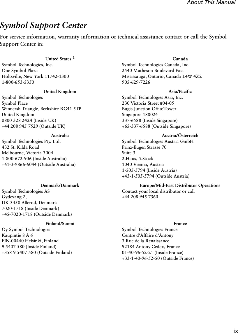
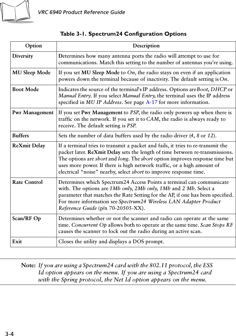
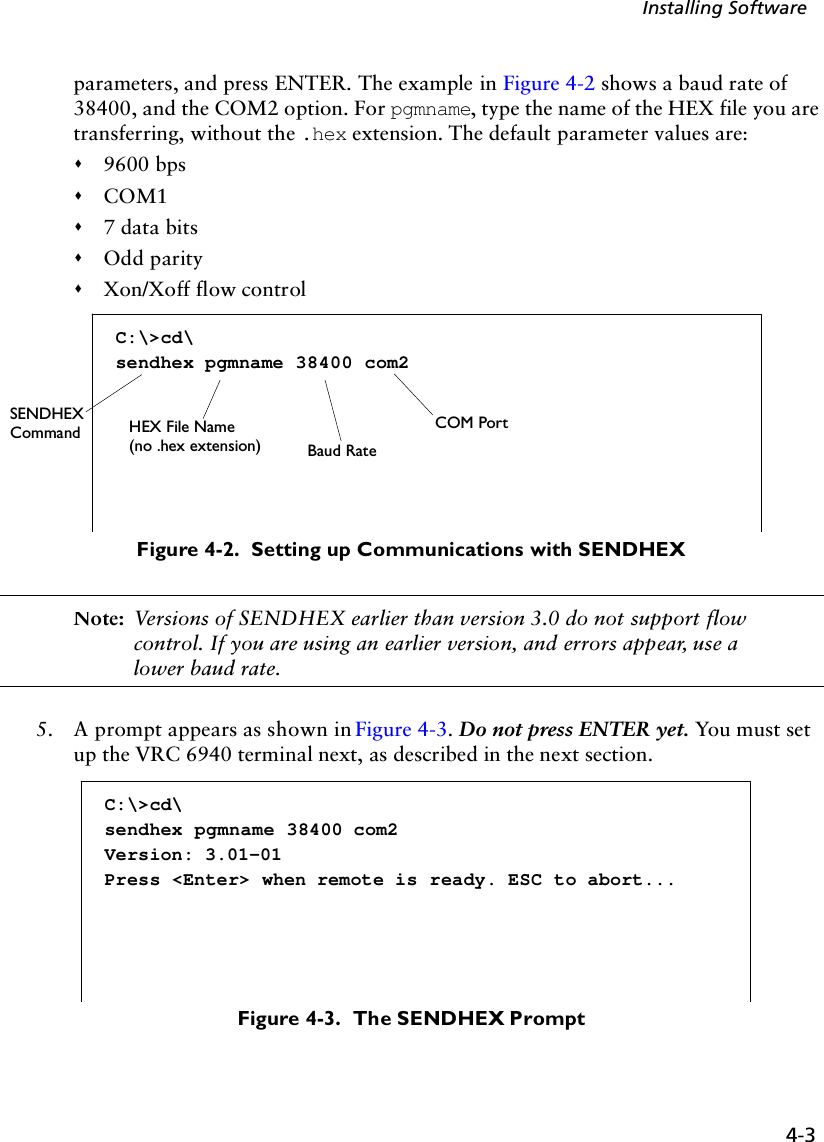
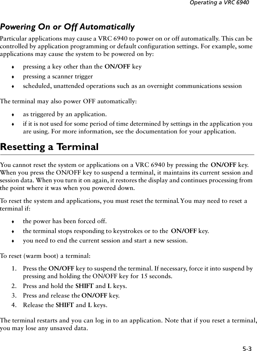
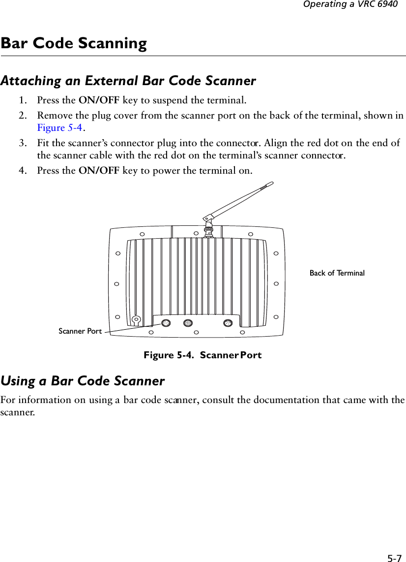
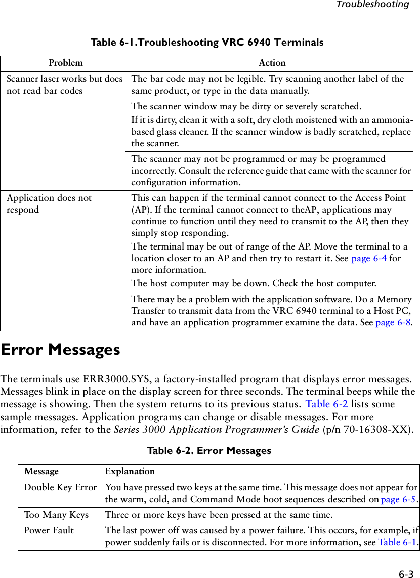
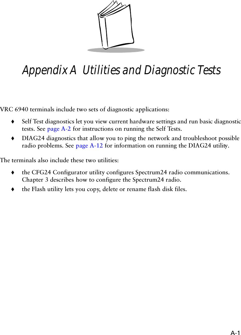
![A-6VRC 6940 Product Reference Guide Note: DIAG24 uses a message file (msg.msg) that it reads from the same drive and directory as the DIAG24 software. If you see corrupted screens, the message file may be missing.4. Select a Roaming Mode. If you want the terminal to ping an AP, but roam between APs as you move around, select Roaming Enabled. If you want to ping a specific AP, select that AP identifier from the list. If more APs are in range than can fit on one screen, then the last selection will be More. Selecting this will present more available APs for selection.Figure A-4 shows a Roaming Enabled option, followed by a list of AP identifiers. For each AP identifier, bb represents the AP identifier (or BSS identifier) and eeeeeeeeeeee represents the 48-bit MAC address of the AP in hexadecimal notation.Figure A-4. Selecting a Roaming Mode5. Press 1, 2 or 3 to select the ping message size:Figure A-5. Selecting Ping Message Size<Test Mode>1. Roaming Enabled2. bb--eeeeeeeeeeee3. bb--eeeeeeeeeeee4. bb--eeeeeeeeeeee....n. bb--eeeeeeeeeeeeSelect[1-n or 'Q']:<Test Mode>MESSAGE SIZE1. 100 bytes2. 256 bytes3. 512 bytesSelect[1-3 or 'Q']:](https://usermanual.wiki/Symbol-Technologies/VRC697C.Product-Reference-Guide/User-Guide-325616-Page-65.png)
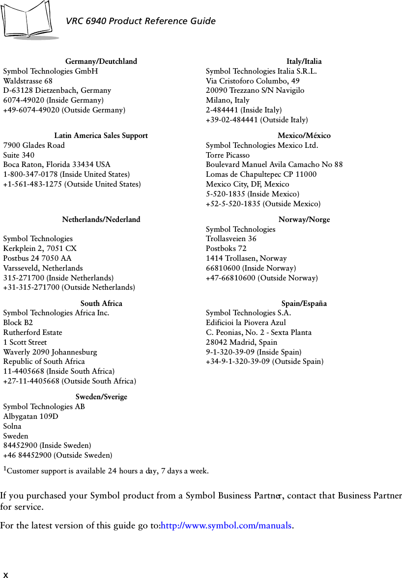
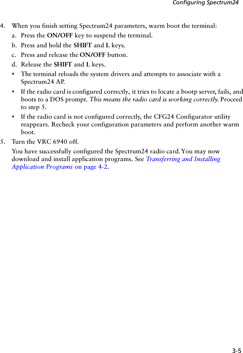
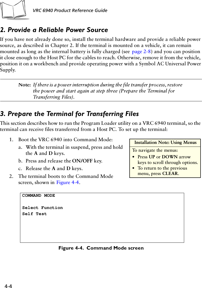
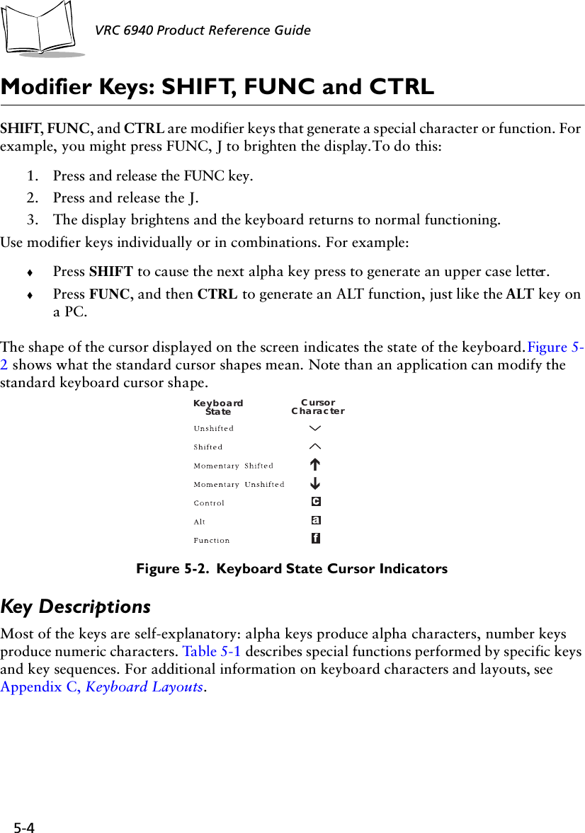
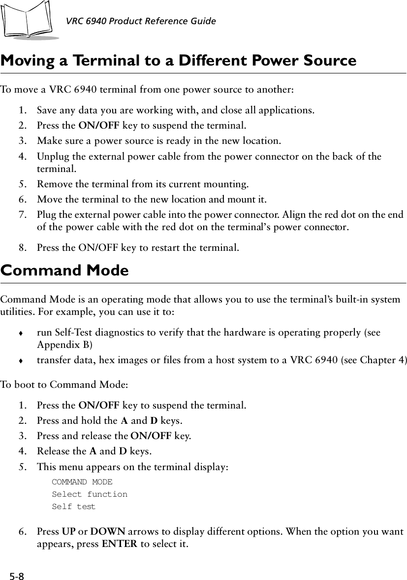
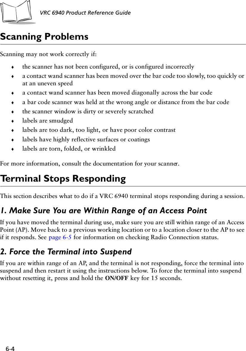
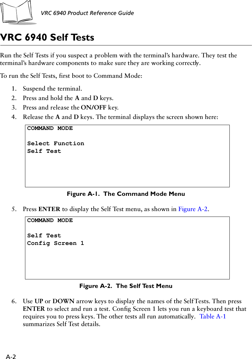
![A-7Utilities and Diagnostic Tests6. Press 1, 2, 3 or 4 to select the number of pings you want to perform:Figure A-6. Selecting the Number of Pings7. Press 1 or 2 to determine whether or not errors will cause the terminal to beep:Figure A-7. Selecting the Number of PingsAfter you select the Beep Mode, the test starts (AP Ping Test or Field Diagnostics test).<Test Mode>NUMBER OF PINGS1. 100 pings2. 500 pings3. 1000 pings4. Non-stopSelect[1-4 or 'Q']:<Test Mode>BEEP MODE1. Beep on error2. SilentSelect[1-2 or 'Q']:](https://usermanual.wiki/Symbol-Technologies/VRC697C.Product-Reference-Guide/User-Guide-325616-Page-66.png)
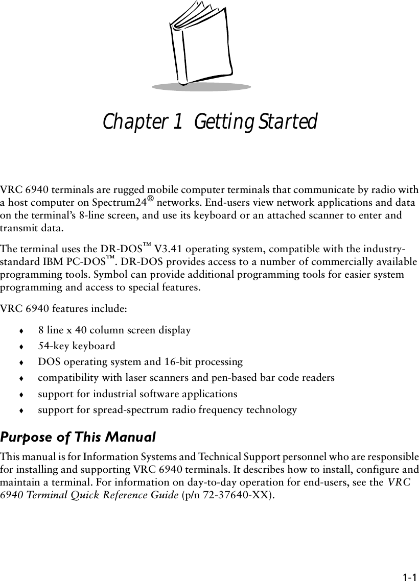
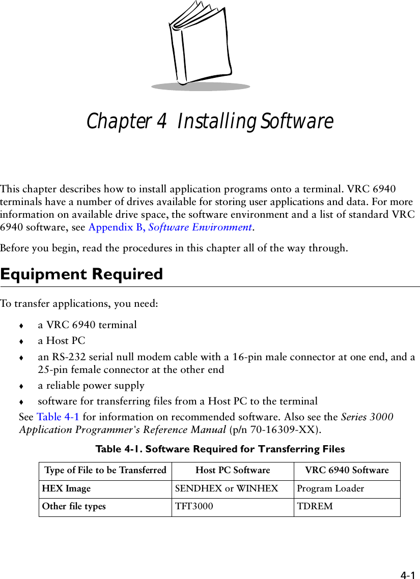
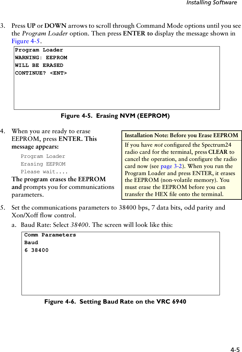
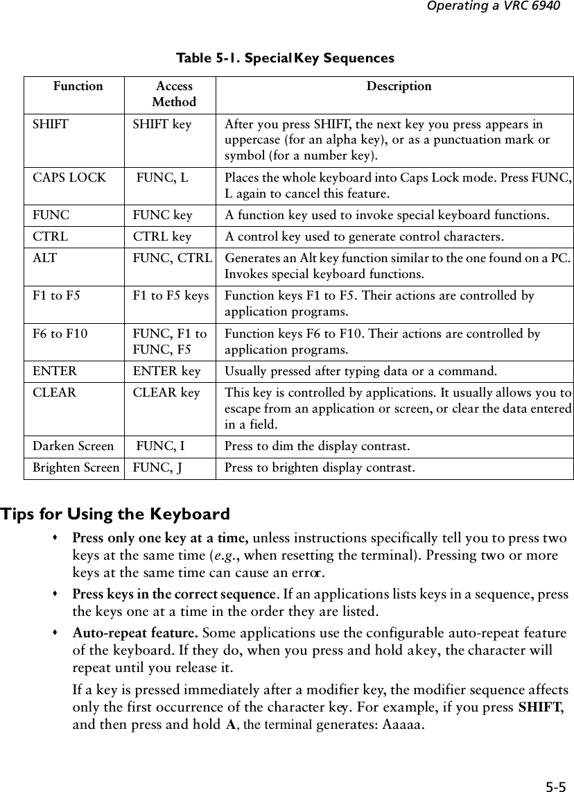
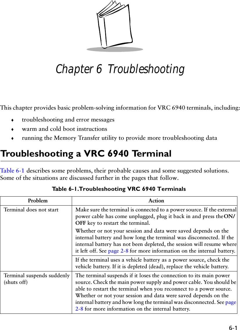
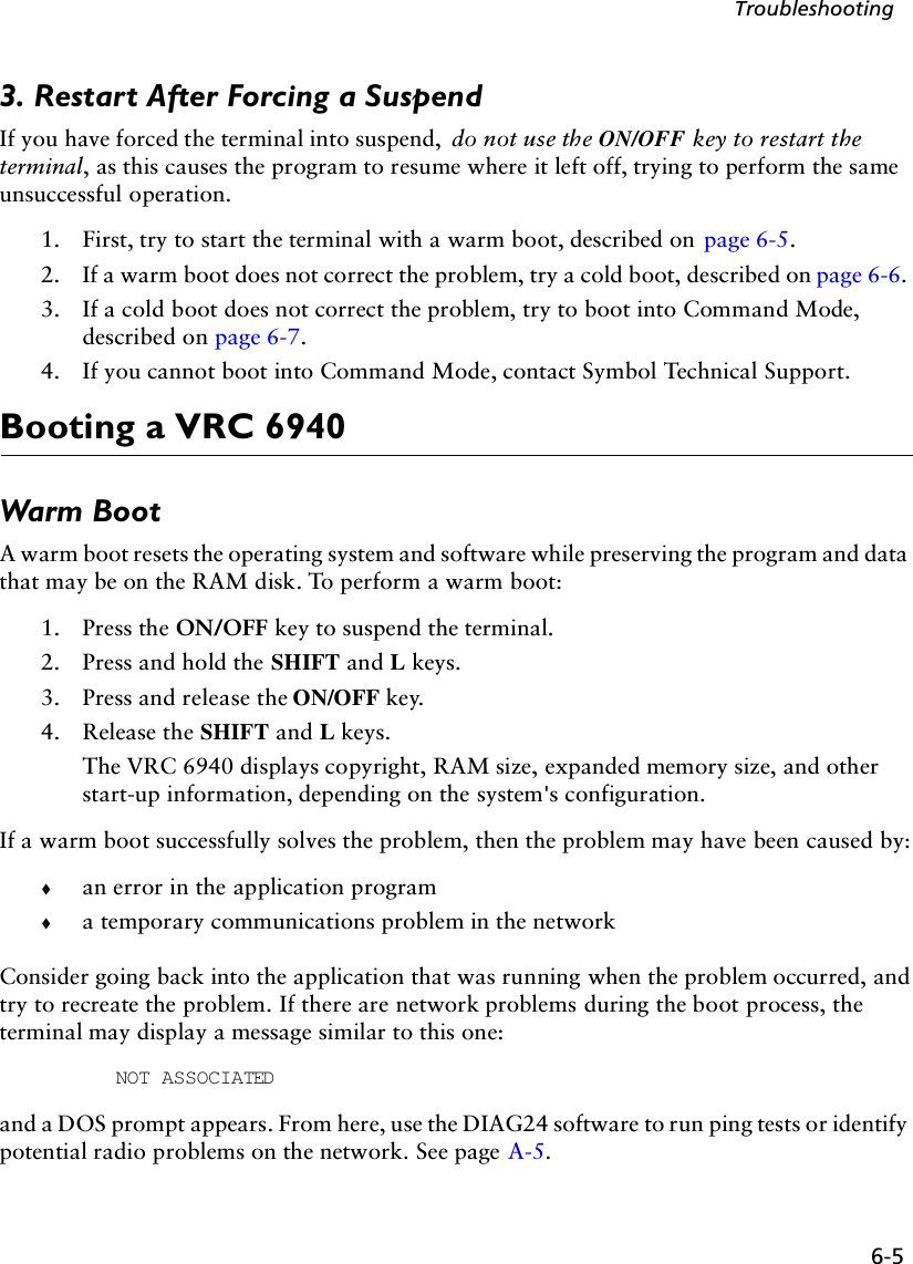
![A-9Utilities and Diagnostic TestsWhen the test stops, the terminal displays a summary screen: Figure A-9. Sample AP Ping Test Results ScreenThe summary shows:!the elapsed time of the test!total pings transmitted!packet size used !retry count !number of timeoutsTo repeat the test with the same parameters, press R. Press Q or CLEAR to end the test and return to the DIAG24 menu.AP PING TESTTotal secs = 7.4RF Secs = 6.7Pings = 100Packet size = 100Timeouts = 4[R]epeat or [Q]uit](https://usermanual.wiki/Symbol-Technologies/VRC697C.Product-Reference-Guide/User-Guide-325616-Page-68.png)
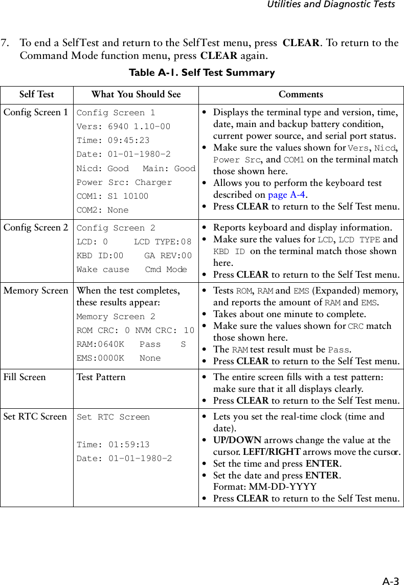
![A-11Utilities and Diagnostic TestsWhen the test stops, the terminal displays a summary screen: Figure A-11. The Field Diagnostic Test Results ScreenThe summary shows:!the elapsed time of the test!total pings transmitted!packet size used !retry count !number of timeoutsTo repeat the test with the same parameters, press R. Press Q or CLEAR to end the test and return to the DIAG24 menu.FIELD DIAGNOSTICSTotal secs = 8.2RF Secs = 4.9Pings = 100Packet size = 100Timeouts = 4[R]epeat or [Q]uit](https://usermanual.wiki/Symbol-Technologies/VRC697C.Product-Reference-Guide/User-Guide-325616-Page-70.png)
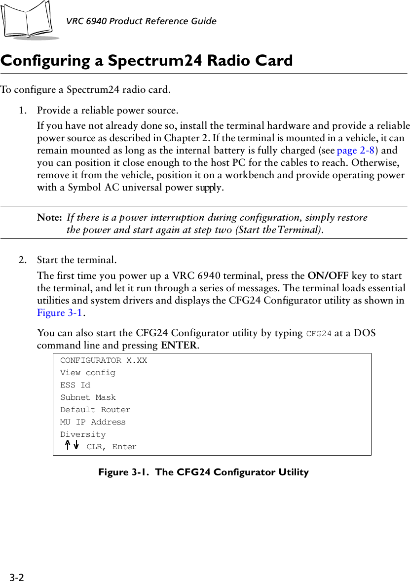
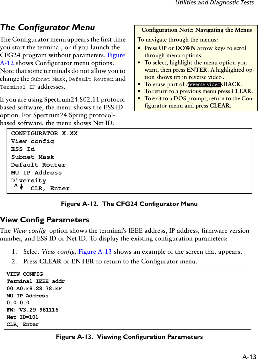
![A-12VRC 6940 Product Reference Guide CFG24 Configurator UtilityThe CFG24 Spectrum24 Configurator utility lets you:!configure radio communication parameters!initialize a configuration stored in the NET.CFG file in the terminal’s current directoryCFG24 updates NET.CFG settings every time it runs. It saves parameter settings to the radio flash storage initialization area, and then checks for an association between the terminal and an Access Point (AP).Note: The Spectrum24 DOS ODI driver must be installed before you use CFG24.Starting the UtilityThere are two ways to start the utility:1. The first time you power up a VRC 6940 terminal the terminal loads essential utilities and system drivers and displays the CFG24 Configurator utility as shown in Figure A-12. 2. Alternate method: go to a DOS prompt and type: CFG24 [-I]. How you get to a DOS prompt depends on what applications have been loaded onto the terminal, and how they have been programmed. The DOS prompt may also appear if you boot the terminal and it cannot connect to the network.The optional parameter [-I] initializes the current configuration. If you are configuring the terminal for the first time, this option starts the utility and displays the Configurator menu.Initializing the RadioWhen you use the [-I] parameter, the utility initializes the radio using the settings currently stored in NET.CFG. Default settings:NET_ID: 101Terminal IP address: 10.x.y.z (x, y, and z are the last 3 bytes of the IEEE address)Subnet mask: 255.0.0.0Default router: 0.0.0.0](https://usermanual.wiki/Symbol-Technologies/VRC697C.Product-Reference-Guide/User-Guide-325616-Page-71.png)


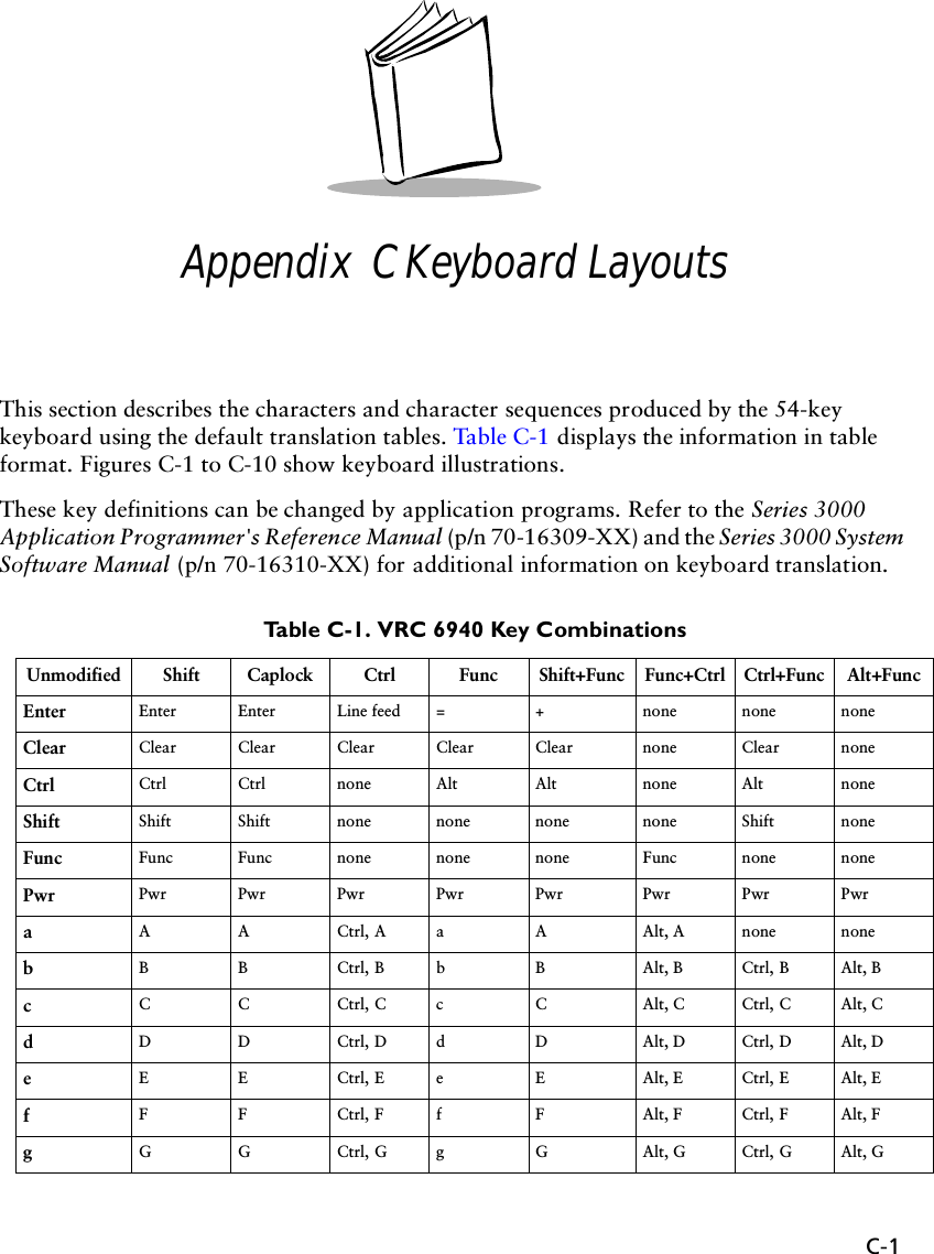
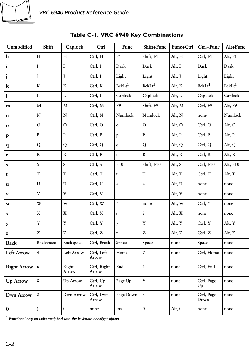
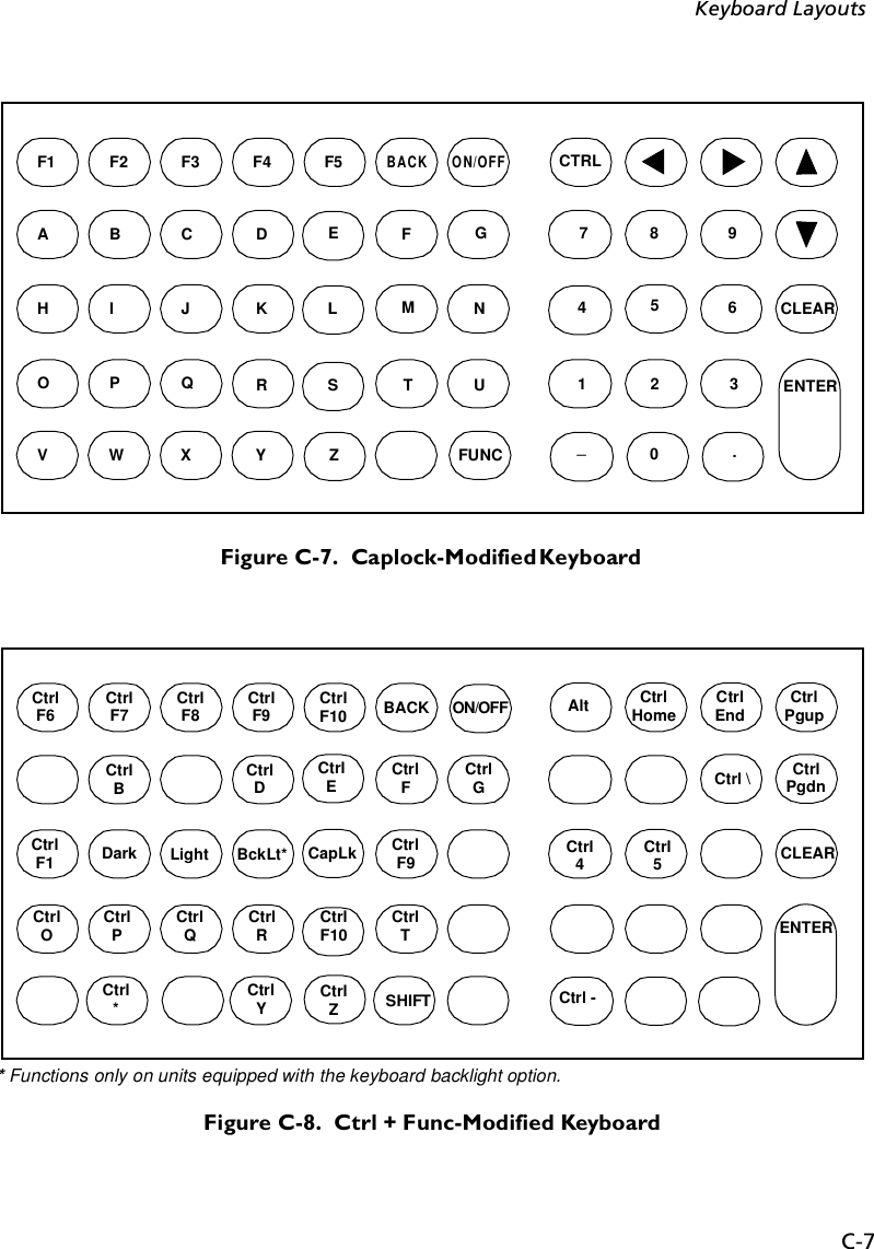
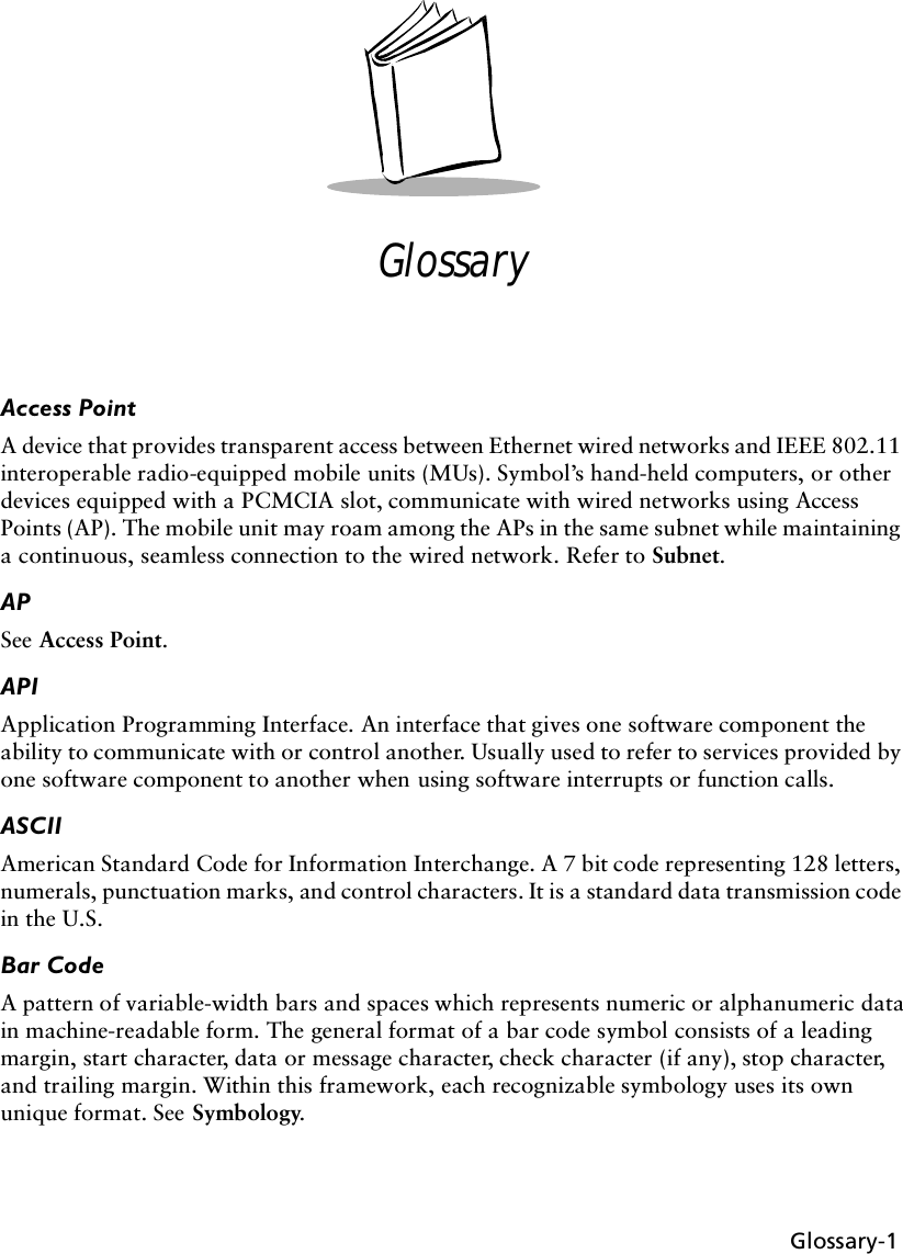
![C-3Keyboard Layouts1! 1 none ’“ Alt, 1 none none2@ 2 Ctrl, 2 , < Alt, 2 none none3# 3 none / ? Alt, 3 none none4$ 4 none [ { Alt, 4 Ctrl, 4 none5% 5 none ] } Alt, 5 Ctrl, 5 none6^ 6 Ctrl, 6 ; : Alt, 6 none none7& 7 none ‘~ Alt, 7 none none8* 8 none = + Alt, 8 none Alt, =9( 9 none \ | Alt, 9 Ctrl, \ none-_ - Ctrl, - - _ Alt, - Ctrl, - Alt, -.> . none Del . none none noneF1 Shift, F1 F1 Ctrl, F1 F6 Shift, F6 Alt, F1 Ctrl, F6 Alt, F6F2 Shift, F2 F2 Ctrl, F2 F7 Shift, F7 Alt, F2 Ctrl, F7 Alt, F7F3 Shift, F3 F3 Ctrl, 3 F8 Shift, F8 Alt, F3 Ctrl, F8 Alt, F8F4 Shift, F4 F4 Ctrl, F4 F9 Shift, F9 Alt, F4 Ctrl, F9 Alt, F9F5 Shift, F5 F5 Ctrl, F5 F10 Shift, F10 Alt, F5 Ctrl, F10 Alt, F10Table C-1. VRC 6940 Key CombinationsUnmodified Shift Caplock Ctrl Func Shift+Func Func+Ctrl Ctrl+Func Alt+Func](https://usermanual.wiki/Symbol-Technologies/VRC697C.Product-Reference-Guide/User-Guide-325616-Page-92.png)
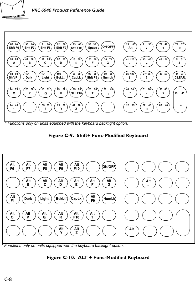
![C-6VRC 6940 Product Reference Guide Figure C-5. Func-Modified KeyboardFigure C-6. Alt-Modified Keyboard81 00PgDn41 96‘13 61=43 92\CLEAR64 00F665 00F766 00F867 00F968 00F1057 32 73 00PgUp29 00Alt 71 00Home 79 00End56 00a48 98b29 00c32 100d18 101e33 102f34 103g59 00F1101Dark102Light100BckLt*58 00CapLk67 00F969 00NumLk24 111o25 112p16 113q19 114r68 00F1020 16t78 43+74 45-55 42*53 47/21 121y44 122z26 91[27 93]39 59;40 39’51 44,53 47/13 61=12 45-82 00Ins 83 00Del01 27Space* Functions only on units equipped with the keyboard backlight option.ON/OFFAltF1Alt 8Alt 4 Alt 6Alt 1 Alt 2 Alt 3Alt - Alt 0AltF2 AltF3 AltF4 AltF5Alt A Alt B Alt C Alt D Alt E Alt F Alt GAlt H Alt I Alt J Alt K Alt L Alt M Alt NAlt O Alt P Alt Q Alt R Alt S Alt T Alt UAlt V Alt W Alt X Alt Y Alt ZAlt 7 Alt 9Alt 5ON/OFF](https://usermanual.wiki/Symbol-Technologies/VRC697C.Product-Reference-Guide/User-Guide-325616-Page-95.png)