Symbol Technologies VRC697C Wireless mobile computer terminal User Manual 3764002c
Symbol Technologies Inc Wireless mobile computer terminal 3764002c
UserManual.wiki
>
Symbol Technologies
>
VRC697C User Manual
>
Quick Reference Guide
Contents
1.
Product Reference Guide
2.
Quick Reference Guide
3.
QRG Addendum
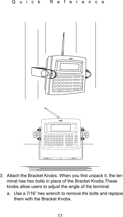
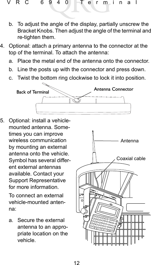
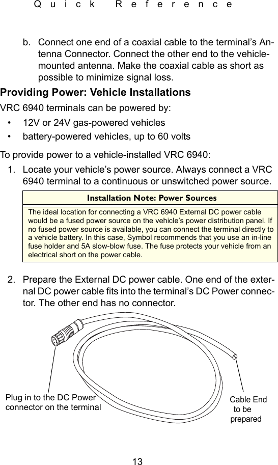
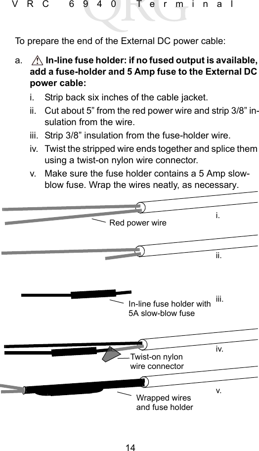
Quick Reference Guide
Navigation menu
Upload a User Manual
Namespaces
Wiki Guide
HTML
PDF
Info
Views
User Manual
Discussion / Help
Navigation