Symbol Technologies VRC697C Wireless mobile computer terminal User Manual VRC 6940 Product Reference Guide
Symbol Technologies Inc Wireless mobile computer terminal VRC 6940 Product Reference Guide
Contents
- 1. Product Reference Guide
- 2. Quick Reference Guide
- 3. QRG Addendum
Product Reference Guide

VRC 6940
Product Reference Guide

VRC 6940
Product Reference Guide
72-37641-02
Revision B
June 2001

ii
2001 by Symbol Technologies, Inc. All rights reserved.
No part of this publication may be reproduced or used in any form, or by any electrical or
mechanical means, without permission in writing from Symbol. This includes electronic or
mechanical means, such as photocopying, recording, or information storage and retrieval
systems. The material in this manual is subject to change without notice.
The software is provided strictly on an “as is” basis. All software, including firmware,
furnished to the user is on a licensed basis. Symbol grants to the user a non-transferable and
non-exclusive license to use each software or firmware program delivered hereunder (licensed
program). Except as noted below, such license may not be assigned, sublicensed, or otherwise
transferred by the user without prior written consent of Symbol. No right to copy a licensed
program in whole or in part is granted, except as permitted under copyright law. The user
shall not modify, merge, or incorporate any form or portion of a licensed program with other
program material, create a derivative work from a licensed program, or use a licensed
program in a network without written permission from Symbol. The user agrees to maintain
Symbol’s copyright notice on the licensed programs delivered hereunder, and to include the
same on any authorized copies it makes, in whole or in part. The user agrees not to
decompile, disassemble, decode, or reverse engineer any licensed program delivered to the
user or any portion thereof.
Symbol reserves the right to make changes to any software or product to improve reliability,
function, or design.
Symbol does not assume any product liability arising out of, or in connection with, the
application or use of any product, circuit, or application described herein.
No license is granted, either expressly or by implication, estoppel, or otherwise under any
Symbol Technologies, Inc., intellectual property rights. An implied license only exists for
equipment, circuits, and subsystems contained in Symbol products.
Symbol, Spectrum One, and Spectrum24 are registered trademarks of Symbol Technologies,
Inc. Other product names mentioned in this manual may be trademarks or registered
trademarks of their respective companies and are hereby acknowledged.
Symbol Technologies, Inc.
One Symbol Plaza
Holtsville, New York 11742-1300
http://www.symbol.com

iii
Contents
About This Manual
Notational Conventions . . . . . . . . . . . . . . . . . . . . . . . . . . . . . . . . . . . . . . . . . . . . . . . . . . . . . . . . . . vii
Related Publications . . . . . . . . . . . . . . . . . . . . . . . . . . . . . . . . . . . . . . . . . . . . . . . . . . . . . . . . . . . . . viii
Contact and Service Information . . . . . . . . . . . . . . . . . . . . . . . . . . . . . . . . . . . . . . . . . . . . . . . . . . . viii
Chapter 1. Getting Started
Purpose of This Manual . . . . . . . . . . . . . . . . . . . . . . . . . . . . . . . . . . . . . . . . . . . . . . . . . . . . . . . . . 1-1
Parts of a VRC 6940 Terminal. . . . . . . . . . . . . . . . . . . . . . . . . . . . . . . . . . . . . . . . . . . . . . . . . . . . 1-2
Options and Accessories. . . . . . . . . . . . . . . . . . . . . . . . . . . . . . . . . . . . . . . . . . . . . . . . . . . . . . . . . 1-3
Options . . . . . . . . . . . . . . . . . . . . . . . . . . . . . . . . . . . . . . . . . . . . . . . . . . . . . . . . . . . . . . . . . . 1-3
Accessories . . . . . . . . . . . . . . . . . . . . . . . . . . . . . . . . . . . . . . . . . . . . . . . . . . . . . . . . . . . . . . . 1-3
Radio Cards . . . . . . . . . . . . . . . . . . . . . . . . . . . . . . . . . . . . . . . . . . . . . . . . . . . . . . . . . . . . . . 1-3
Scanners . . . . . . . . . . . . . . . . . . . . . . . . . . . . . . . . . . . . . . . . . . . . . . . . . . . . . . . . . . . . . . . . . 1-3
Printers . . . . . . . . . . . . . . . . . . . . . . . . . . . . . . . . . . . . . . . . . . . . . . . . . . . . . . . . . . . . . . . . . . 1-4
Before You Use the Terminal.... . . . . . . . . . . . . . . . . . . . . . . . . . . . . . . . . . . . . . . . . . . . . . . . . . . . 1-4
Chapter 2. Installing Hardware
Equipment Required. . . . . . . . . . . . . . . . . . . . . . . . . . . . . . . . . . . . . . . . . . . . . . . . . . . . . . . . . . . . 2-1
Hardware Installation. . . . . . . . . . . . . . . . . . . . . . . . . . . . . . . . . . . . . . . . . . . . . . . . . . . . . . . . . . . 2-2
Providing Power: Vehicle Installations . . . . . . . . . . . . . . . . . . . . . . . . . . . . . . . . . . . . . . . . . . . . . . 2-5
Providing Power: Wall or Workbench Installations . . . . . . . . . . . . . . . . . . . . . . . . . . . . . . . . . . . . 2-7
Installation and the Internal Battery . . . . . . . . . . . . . . . . . . . . . . . . . . . . . . . . . . . . . . . . . . . . . . . . 2-8
Chapter 3. Configuring Spectrum24
Equipment Required. . . . . . . . . . . . . . . . . . . . . . . . . . . . . . . . . . . . . . . . . . . . . . . . . . . . . . . . . . . . 3-1
Configuring a Spectrum24 Radio Card. . . . . . . . . . . . . . . . . . . . . . . . . . . . . . . . . . . . . . . . . . . . . . 3-2

iv
VRC 6940 Product Reference Guide
Chapter 4. Installing Software
Equipment Required . . . . . . . . . . . . . . . . . . . . . . . . . . . . . . . . . . . . . . . . . . . . . . . . . . . . . . . . . . . . 4-1
Transferring and Installing Application Programs . . . . . . . . . . . . . . . . . . . . . . . . . . . . . . . . . . . . . . 4-2
1. Prepare the PC for Communications and File Downloading. . . . . . . . . . . . . . . . . . . . . . . . . 4-2
2. Provide a Reliable Power Source. . . . . . . . . . . . . . . . . . . . . . . . . . . . . . . . . . . . . . . . . . . . . . 4-4
3. Prepare the Terminal for Transferring Files . . . . . . . . . . . . . . . . . . . . . . . . . . . . . . . . . . . . . 4-4
4. Start the File Transfer. . . . . . . . . . . . . . . . . . . . . . . . . . . . . . . . . . . . . . . . . . . . . . . . . . . . . . 4-7
5. Complete the Installation of Transferred Files . . . . . . . . . . . . . . . . . . . . . . . . . . . . . . . . . . . 4-8
Chapter 5. Operating a VRC 6940
Powering a Terminal On and Off . . . . . . . . . . . . . . . . . . . . . . . . . . . . . . . . . . . . . . . . . . . . . . . . . . 5-2
Powering On . . . . . . . . . . . . . . . . . . . . . . . . . . . . . . . . . . . . . . . . . . . . . . . . . . . . . . . . . . . . . . 5-2
Suspending or Turning Off the Terminal . . . . . . . . . . . . . . . . . . . . . . . . . . . . . . . . . . . . . . . . . 5-2
Powering On or Off Automatically. . . . . . . . . . . . . . . . . . . . . . . . . . . . . . . . . . . . . . . . . . . . . . 5-3
Resetting a Terminal . . . . . . . . . . . . . . . . . . . . . . . . . . . . . . . . . . . . . . . . . . . . . . . . . . . . . . . . . . . . 5-3
Modifier Keys: SHIFT, FUNC and CTRL . . . . . . . . . . . . . . . . . . . . . . . . . . . . . . . . . . . . . . . . . . . . 5-4
Adjusting Brightness . . . . . . . . . . . . . . . . . . . . . . . . . . . . . . . . . . . . . . . . . . . . . . . . . . . . . . . . . . . . 5-6
Entering Data . . . . . . . . . . . . . . . . . . . . . . . . . . . . . . . . . . . . . . . . . . . . . . . . . . . . . . . . . . . . . . . . . 5-6
Bar Code Scanning. . . . . . . . . . . . . . . . . . . . . . . . . . . . . . . . . . . . . . . . . . . . . . . . . . . . . . . . . . . . . . 5-7
Attaching an External Bar Code Scanner . . . . . . . . . . . . . . . . . . . . . . . . . . . . . . . . . . . . . . . . . 5-7
Using a Bar Code Scanner. . . . . . . . . . . . . . . . . . . . . . . . . . . . . . . . . . . . . . . . . . . . . . . . . . . . .5-7
Moving a Terminal to a Different Power Source . . . . . . . . . . . . . . . . . . . . . . . . . . . . . . . . . . . . . . . 5-8
Command Mode . . . . . . . . . . . . . . . . . . . . . . . . . . . . . . . . . . . . . . . . . . . . . . . . . . . . . . . . . . . . . . . 5-8
Chapter 6. Troubleshooting
Troubleshooting a VRC 6940 Terminal. . . . . . . . . . . . . . . . . . . . . . . . . . . . . . . . . . . . . . . . . . . . . . 6-1
Error Messages . . . . . . . . . . . . . . . . . . . . . . . . . . . . . . . . . . . . . . . . . . . . . . . . . . . . . . . . . . . . . . . . 6-3
Scanning Problems. . . . . . . . . . . . . . . . . . . . . . . . . . . . . . . . . . . . . . . . . . . . . . . . . . . . . . . . . . . . . . 6-4
Terminal Stops Responding . . . . . . . . . . . . . . . . . . . . . . . . . . . . . . . . . . . . . . . . . . . . . . . . . . . . . . . 6-4
1. Make Sure You are Within Range of an Access Point. . . . . . . . . . . . . . . . . . . . . . . . . . . . . . 6-4
2. Force the Terminal into Suspend . . . . . . . . . . . . . . . . . . . . . . . . . . . . . . . . . . . . . . . . . . . . . 6-4
3. Restart After Forcing a Suspend . . . . . . . . . . . . . . . . . . . . . . . . . . . . . . . . . . . . . . . . . . . . . . 6-5
Booting a VRC 6940 . . . . . . . . . . . . . . . . . . . . . . . . . . . . . . . . . . . . . . . . . . . . . . . . . . . . . . . . . . . . 6-5
Warm Boot. . . . . . . . . . . . . . . . . . . . . . . . . . . . . . . . . . . . . . . . . . . . . . . . . . . . . . . . . . . . . . . . 6-5
Cold Boot . . . . . . . . . . . . . . . . . . . . . . . . . . . . . . . . . . . . . . . . . . . . . . . . . . . . . . . . . . . . . . . . . 6-6
Command Mode . . . . . . . . . . . . . . . . . . . . . . . . . . . . . . . . . . . . . . . . . . . . . . . . . . . . . . . . . . . 6-7
If Rebooting Fails . . . . . . . . . . . . . . . . . . . . . . . . . . . . . . . . . . . . . . . . . . . . . . . . . . . . . . . . . . . 6-7
Memory Transfer Analyzer (MTA) Utility . . . . . . . . . . . . . . . . . . . . . . . . . . . . . . . . . . . . . . . . . . . 6-8
Technical Support Contacts. . . . . . . . . . . . . . . . . . . . . . . . . . . . . . . . . . . . . . . . . . . . . . . . . . . . . . 6-12

v
Contents
Chapter 7. Maintenance
Maintaining the Internal Battery. . . . . . . . . . . . . . . . . . . . . . . . . . . . . . . . . . . . . . . . . . . . . . . . . . . 7-1
Storing the Terminal. . . . . . . . . . . . . . . . . . . . . . . . . . . . . . . . . . . . . . . . . . . . . . . . . . . . . . . . . . . . 7-2
Cleaning . . . . . . . . . . . . . . . . . . . . . . . . . . . . . . . . . . . . . . . . . . . . . . . . . . . . . . . . . . . . . . . . . . . . . 7-2
Appendix A. Utilities and Diagnostic Tests
VRC 6940 Self Tests. . . . . . . . . . . . . . . . . . . . . . . . . . . . . . . . . . . . . . . . . . . . . . . . . . . . . . . . . . . . A-2
Keyboard Test. . . . . . . . . . . . . . . . . . . . . . . . . . . . . . . . . . . . . . . . . . . . . . . . . . . . . . . . . . . . . A-4
DIAG24 Diagnostics Utility . . . . . . . . . . . . . . . . . . . . . . . . . . . . . . . . . . . . . . . . . . . . . . . . . . . . . . A-5
DIAG24 Setup. . . . . . . . . . . . . . . . . . . . . . . . . . . . . . . . . . . . . . . . . . . . . . . . . . . . . . . . . . . . . A-5
Ping Test . . . . . . . . . . . . . . . . . . . . . . . . . . . . . . . . . . . . . . . . . . . . . . . . . . . . . . . . . . . . . . . . . A-8
Field Diagnostic Test. . . . . . . . . . . . . . . . . . . . . . . . . . . . . . . . . . . . . . . . . . . . . . . . . . . . . . . A-10
CFG24 Configurator Utility . . . . . . . . . . . . . . . . . . . . . . . . . . . . . . . . . . . . . . . . . . . . . . . . . . . . . A-12
Starting the Utility. . . . . . . . . . . . . . . . . . . . . . . . . . . . . . . . . . . . . . . . . . . . . . . . . . . . . . . . . A-12
Initializing the Radio. . . . . . . . . . . . . . . . . . . . . . . . . . . . . . . . . . . . . . . . . . . . . . . . . . . . . . . A-12
The Configurator Menu . . . . . . . . . . . . . . . . . . . . . . . . . . . . . . . . . . . . . . . . . . . . . . . . . . . . A-13
View Config Parameters. . . . . . . . . . . . . . . . . . . . . . . . . . . . . . . . . . . . . . . . . . . . . . . . . A-13
ESS ID or Net ID . . . . . . . . . . . . . . . . . . . . . . . . . . . . . . . . . . . . . . . . . . . . . . . . . . . . . . A-14
Subnet Mask . . . . . . . . . . . . . . . . . . . . . . . . . . . . . . . . . . . . . . . . . . . . . . . . . . . . . . . . . A-14
Default Router . . . . . . . . . . . . . . . . . . . . . . . . . . . . . . . . . . . . . . . . . . . . . . . . . . . . . . . . A-15
Terminal IP Address. . . . . . . . . . . . . . . . . . . . . . . . . . . . . . . . . . . . . . . . . . . . . . . . . . . . A-16
Diversity . . . . . . . . . . . . . . . . . . . . . . . . . . . . . . . . . . . . . . . . . . . . . . . . . . . . . . . . . . . . A-16
MU Sleep Mode . . . . . . . . . . . . . . . . . . . . . . . . . . . . . . . . . . . . . . . . . . . . . . . . . . . . . . . A-17
Boot Mode . . . . . . . . . . . . . . . . . . . . . . . . . . . . . . . . . . . . . . . . . . . . . . . . . . . . . . . . . . . A-17
Power Management . . . . . . . . . . . . . . . . . . . . . . . . . . . . . . . . . . . . . . . . . . . . . . . . . . . . A-18
Buffers . . . . . . . . . . . . . . . . . . . . . . . . . . . . . . . . . . . . . . . . . . . . . . . . . . . . . . . . . . . . . . A-19
Re-Transmit Delay. . . . . . . . . . . . . . . . . . . . . . . . . . . . . . . . . . . . . . . . . . . . . . . . . . . . . A-19
Rate Control . . . . . . . . . . . . . . . . . . . . . . . . . . . . . . . . . . . . . . . . . . . . . . . . . . . . . . . . . A-20
Scanner/RF Operation . . . . . . . . . . . . . . . . . . . . . . . . . . . . . . . . . . . . . . . . . . . . . . . . . . A-20
Flash Utility . . . . . . . . . . . . . . . . . . . . . . . . . . . . . . . . . . . . . . . . . . . . . . . . . . . . . . . . . . . . . . . . . A-21
Deleting. . . . . . . . . . . . . . . . . . . . . . . . . . . . . . . . . . . . . . . . . . . . . . . . . . . . . . . . . . . . . . . . . A-21
Copying . . . . . . . . . . . . . . . . . . . . . . . . . . . . . . . . . . . . . . . . . . . . . . . . . . . . . . . . . . . . . . . . A-21
Renaming . . . . . . . . . . . . . . . . . . . . . . . . . . . . . . . . . . . . . . . . . . . . . . . . . . . . . . . . . . . . . . . A-21
Appendix B. Software Environment
Boot Sequence . . . . . . . . . . . . . . . . . . . . . . . . . . . . . . . . . . . . . . . . . . . . . . . . . . . . . . . . . . . . . . . . B-2
LAN WorkPlace (LWP) Software . . . . . . . . . . . . . . . . . . . . . . . . . . . . . . . . . . . . . . . . . . . . . . . . . . B-3
Software Files . . . . . . . . . . . . . . . . . . . . . . . . . . . . . . . . . . . . . . . . . . . . . . . . . . . . . . . . . . . . . . . . . B-3

vi
VRC 6940 Product Reference Guide
Appendix C. Keyboard Layouts
Keyboard Character & Character Combination Illustrations. . . . . . . . . . . . . . . . . . . . . . . . . . . . . . C-4
Appendix D. Environmental and Technical Specifications
Specifications . . . . . . . . . . . . . . . . . . . . . . . . . . . . . . . . . . . . . . . . . . . . . . . . . . . . . . . . . . . . . . . . . D-1
Scanner Port . . . . . . . . . . . . . . . . . . . . . . . . . . . . . . . . . . . . . . . . . . . . . . . . . . . . . . . . . . . . . . . . . D-2
COM1 Serial Port . . . . . . . . . . . . . . . . . . . . . . . . . . . . . . . . . . . . . . . . . . . . . . . . . . . . . . . . . . . . . D-3
Null Modem . . . . . . . . . . . . . . . . . . . . . . . . . . . . . . . . . . . . . . . . . . . . . . . . . . . . . . . . . . . . . . . . . D-4
Appendix E. Communications Status Codes
Communications Status Codes. . . . . . . . . . . . . . . . . . . . . . . . . . . . . . . . . . . . . . . . . . . . . . . . . . . . . E-1
Glossary
Index

vii
About This Manual
This Product Reference Guide describes the VRC 6940 terminal. Topics include: hardware
installation, software configuration, operation, troubleshooting, and maintenance.
Notational Conventions
This document uses the following conventions:
!“Operator” or “User” refers to anyone using a VRC 6940 terminal.
!“Te rmin al” refers to a VRC 6940 terminal.
!“You” refers to the System Administrator or Technical Support person using this
manual to install, configure, operate, maintain or troubleshoot a VRC 6940.
!Bold upper case type indicates a key on the terminal. For example: “Press ENTER”,
“Press J, then K”.
!Courier type is used for command line text and file names.
!Italics are used:
"to identify menu items on a terminal screen
"for variable names in usage and syntax descriptions
"to highlight specific items in the general text
"to identify chapters and sections in this and related documents
!Bullets (♦) indicate:
"action items
"lists of alternatives
"lists of required steps that are not necessarily sequential
!Sequential lists (e.g., those that describe step-by-step procedures) appear as
numbered lists.

viii
VRC 6940 Product Reference Guide
Related Publications
!VRC 6900 Series Quick Reference Guide
p/n 72-37640-XX
!Series 3000 Application Programmer's Guide
p/n 70-16308-XX
!Series 3000 Application Programmer’s Reference Manual
p/n 70-16309-XX
!Series 3000 System Software Manual
p/n 70-16310-XX
!Spectrum 24 Network Terminal Technical Reference Guide — Radio Firmware and
Driver Guide Version 3
p/n 70-20193-XX
!Spectrum 24 Ethernet Access Point User Guide
p/n 70-12057-XX
!Spectrum24 Wireless LAN Adapter Product Reference Guide
p/n 70-20505-XX
Contact and Service Information
If you have a problem with your equipment, contact the Symbol Support Center for your region. See
page vii for contact information. Before calling, have the model number, serial number, and several of
your bar code symbols at hand.
Call the Support Center from a phone near the scanning equipment so that the service person can try
to talk you through your problem. If the equipment is found to be working properly and the problem
is symbol readability, the Support Center will request samples of your bar codes for analysis at our
plant.
If your problem cannot be solved over the phone, you may need to return your equipment for servicing.
If that is necessary, you will be given specific directions.
Note: Symbol Technologies is not responsible for any damages incurred during
shipment if the approved shipping container is not used. Shipping the units
improperly can possibly void the warranty. If the original shipping container
was not kept, contact Symbol to have another sent to you.

ix
About This Manual
Symbol Support Center
For service information, warranty information or technical assistance contact or call the Symbol
Support Center in:
United States 1
Symbol Technologies, Inc.
One Symbol Plaza
Holtsville, New York 11742-1300
1-800-653-5350
Canada
Symbol Technologies Canada, Inc.
2540 Matheson Boulevard East
Mississauga, Ontario, Canada L4W 4Z2
905-629-7226
United Kingdom
Symbol Technologies
Symbol Place
Winnersh Triangle, Berkshire RG41 5TP
United Kingdom
0800 328 2424 (Inside UK)
+44 208 945 7529 (Outside UK)
Asia/Pacific
Symbol Technologies Asia, Inc.
230 Victoria Street #04-05
Bugis Junction Office Tower
Singapore 188024
337-6588 (Inside Singapore)
+65-337-6588 (Outside Singapore)
Australia
Symbol Technologies Pty. Ltd.
432 St. Kilda Road
Melbourne, Victoria 3004
1-800-672-906 (Inside Australia)
+61-3-9866-6044 (Outside Australia)
Austria/Österreich
Symbol Technologies Austria GmbH
Prinz-Eugen Strasse 70
Suite 3
2.Haus, 5.Stock
1040 Vienna, Austria
1-505-5794 (Inside Austria)
+43-1-505-5794 (Outside Austria)
Denmark/Danmark
Symbol Technologies AS
Gydevang 2,
DK-3450 Allerod, Denmark
7020-1718 (Inside Denmark)
+45-7020-1718 (Outside Denmark)
Europe/Mid-East Distributor Operations
Contact your local distributor or call
+44 208 945 7360
Finland/Suomi
Oy Symbol Technologies
Kaupintie 8 A 6
FIN-00440 Helsinki, Finland
9 5407 580 (Inside Finland)
+358 9 5407 580 (Outside Finland)
France
Symbol Technologies France
Centre d'Affaire d'Antony
3 Rue de la Renaissance
92184 Antony Cedex, France
01-40-96-52-21 (Inside France)
+33-1-40-96-52-50 (Outside France)

x
VRC 6940 Product Reference Guide
If you purchased your Symbol product from a Symbol Business Partner, contact that Business Partner
for service.
For the latest version of this guide go to:http://www.symbol.com/manuals.
Germany/Deutchland
Symbol Technologies GmbH
Waldstrasse 68
D-63128 Dietzenbach, Germany
6074-49020 (Inside Germany)
+49-6074-49020 (Outside Germany)
Italy/Italia
Symbol Technologies Italia S.R.L.
Via Cristoforo Columbo, 49
20090 Trezzano S/N Navigilo
Milano, Italy
2-484441 (Inside Italy)
+39-02-484441 (Outside Italy)
Latin America Sales Support
7900 Glades Road
Suite 340
Boca Raton, Florida 33434 USA
1-800-347-0178 (Inside United States)
+1-561-483-1275 (Outside United States)
Mexico/México
Symbol Technologies Mexico Ltd.
Torre Picasso
Boulevard Manuel Avila Camacho No 88
Lomas de Chapultepec CP 11000
Mexico City, DF, Mexico
5-520-1835 (Inside Mexico)
+52-5-520-1835 (Outside Mexico)
Netherlands/Nederland
Symbol Technologies
Kerkplein 2, 7051 CX
Postbus 24 7050 AA
Varsseveld, Netherlands
315-271700 (Inside Netherlands)
+31-315-271700 (Outside Netherlands)
Norway/Norge
Symbol Technologies
Trollasveien 36
Postboks 72
1414 Trollasen, Norway
66810600 (Inside Norway)
+47-66810600 (Outside Norway)
South Africa
Symbol Technologies Africa Inc.
Block B2
Rutherford Estate
1 Scott Street
Waverly 2090 Johannesburg
Republic of South Africa
11-4405668 (Inside South Africa)
+27-11-4405668 (Outside South Africa)
Spain/España
Symbol Technologies S.A.
Edificioi la Piovera Azul
C. Peonias, No. 2 - Sexta Planta
28042 Madrid, Spain
9-1-320-39-09 (Inside Spain)
+34-9-1-320-39-09 (Outside Spain)
Sweden/Sverige
Symbol Technologies AB
Albygatan 109D
Solna
Sweden
84452900 (Inside Sweden)
+46 84452900 (Outside Sweden)
1Customer support is available 24 hours a day, 7 days a week.

1-1
Chapter 1 Getting Started
VRC 6940 terminals are rugged mobile computer terminals that communicate by radio with
a host computer on Spectrum24® networks. End-users view network applications and data
on the terminal’s 8-line screen, and use its keyboard or an attached scanner to enter and
transmit data.
The terminal uses the DR-DOS™ V3.41 operating system, compatible with the industry-
standard IBM PC-DOS™. DR-DOS provides access to a number of commercially available
programming tools. Symbol can provide additional programming tools for easier system
programming and access to special features.
VRC 6940 features include:
!8 line x 40 column screen display
!54-key keyboard
!DOS operating system and 16-bit processing
!compatibility with laser scanners and pen-based bar code readers
!support for industrial software applications
!support for spread-spectrum radio frequency technology
Purpose of This Manual
This manual is for Information Systems and Technical Support personnel who are responsible
for installing and supporting VRC 6940 terminals. It describes how to install, configure and
maintain a terminal. For information on day-to-day operation for end-users, see the VRC
6940 Terminal Quick Reference Guide (p/n 72-37640-XX).
1-2
VRC 6940 Product Reference Guide
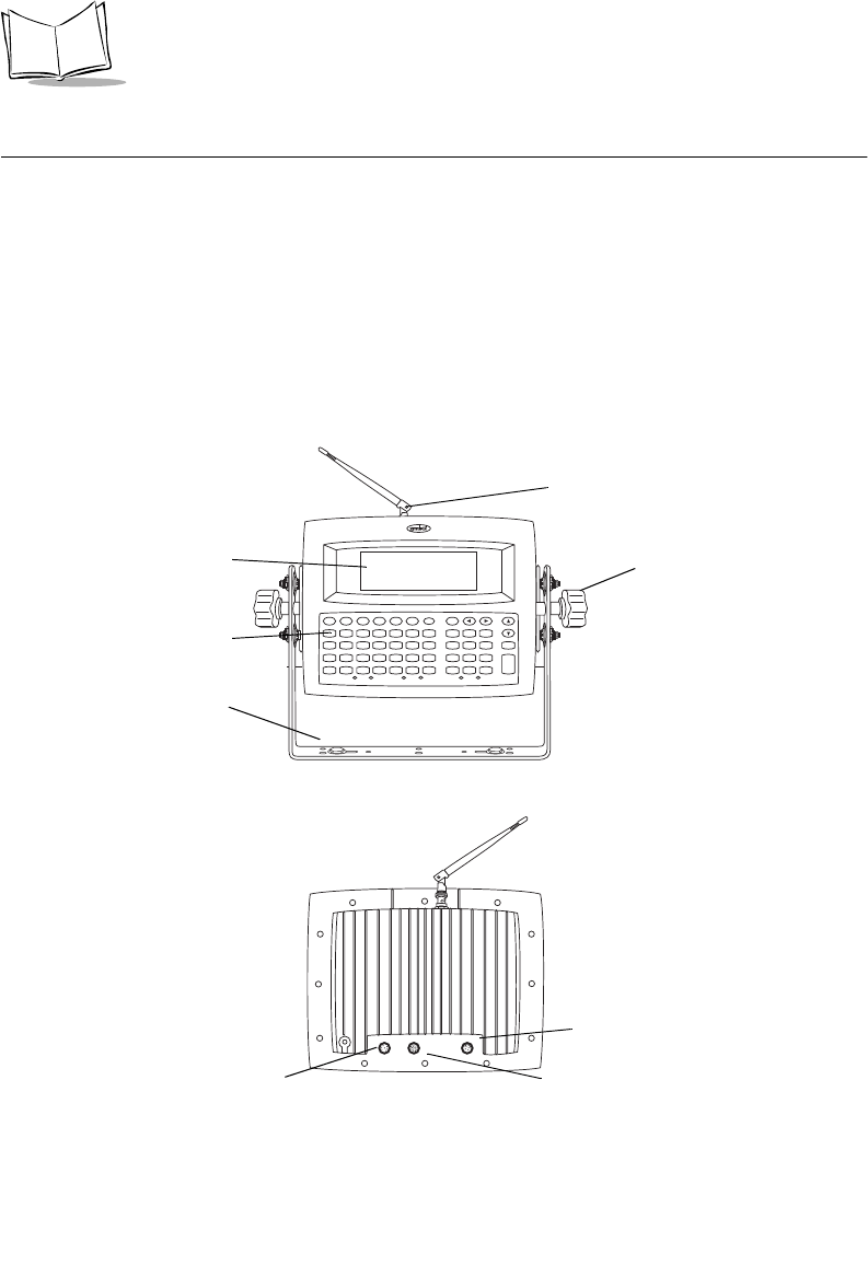
Parts of a VRC 6940 Terminal
Standard Parts
A standard VRC 6940 terminal includes these standard parts:
!Terminal with attached vehicle-mount bracket
!Bracket knobs (2)
!External DC power cable
!Internal PCMCIA radio card for use with a Symbol Spectrum24 network
!VRC 6940 Terminal Quick Reference Guide (p/n 72-37640-XX)
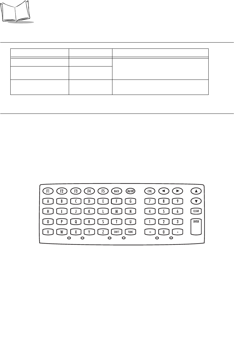
Figure 1-1. Parts of a VRC 6940
F1 F2 F3 F4 F5 BACK ON/OFF CTRL
9
ABCDEFG 78
6
HIJKLMN 45 CLEAR
3
OPQRSTU 12 ENTER
.
VWXY Z
SHIFT FUNC -0
Antenna (accessory option)
Bracket Knob
Ve h i c l e - mo u n t B r a c ke t
Display Screen
Keyb oa rd
Scanner Connector
(Remove plug cover
before using) RS-232 Connector
(Remove plug cover before using)
Power Connector
Front
Back

1-3
Getting Started
Options and Accessories
Options
You can also order the VRC 6940 with these options:
!Keyboard backlight
!Internal heating device
Accessories
You can order these VRC 6940 accessories separately from Symbol:
!Scanner cable
!RS-232 cable
!Primary antenna
!Vehicle-mounted antenna
!Spectrum24® PCMCIA radio card
!AC Universal Power Supply
!AC cable
!DC cable
Note: Contact your Symbol Sales representative to order the cable
appropriate for your country.
Radio Cards
VRC 6940 models include an internal PCMCIA radio card for use with a Symbol Spectrum24
network. For other information on radio cards, contact Symbol Technologies.
Scanners
The VRC 6940 terminal can use these Symbol laser scanner models:
!LS 2000 !LS 9100
!LS 3000 !LT 1700
!LS 5000

1-4
VRC 6940 Product Reference Guide
Printers
The VRC 6940 terminal can use these Symbol printer models:
Before You Use the Terminal...
!PS 1000 !PS 200
Table 1-1. VRC 6940 Installation and Configuration Tasks
Task Where to Find the Instructions
Install the hardware in a vehicle or
forklift, or on a wall or workbench.
See Hardware Installation page 2-2.
Provide a primary AC or DC power
source.
See Providing Power: Vehicle Installations on
page 2-5.
Charge the internal battery. See Installation and the Internal Battery on page
2-8.
Configure the radio card. See Configuring a Spectrum24 Radio Card on
page 3-2.
Transfer, install and configure software. See Transferring and Installing Application
Programs on page 4-2.

2-1
Chapter 2 Installing Hardware
This chapter describes how to install a VRC 6940 terminal into a vehicle or onto a wall or
workbench. Please read all of these instructions before you begin.
Caution
A properly trained technician must perform the installation. Improper
installation can damage your vehicle.
Equipment Required
Vehicle Mounted VRC 6940
!an External DC power cable (supplied with terminal).
!minimum of two 3/8” bolts with self-locking nylon nuts.
!a drill with a 7/16” drill bit.
!7/16” hex wrench.
!a connector for terminating the External DC power cable. Select one that mates with
your vehicle’s power supply.
!primary or external antenna (optional).
Wall or Workbench Mounted VRC 6940
!AC universal power supply (Symbol p/n 50-14001-006)
!AC line cable (Symbol p/n 23844-00-00)
!DC power cable (Symbol p/n 25-39385-01)
!minimum of two 3/8” bolts with self-locking nylon nuts
2-2
VRC 6940 Product Reference Guide
!a drill with a 7/16” drill bit
!7/16” hex wrench
!primary or external antenna (optional)
Hardware Installation
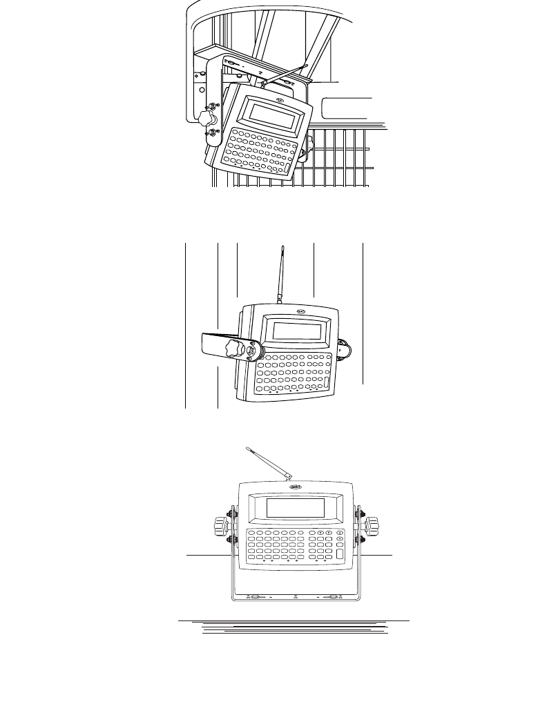
The physical requirements of the work area affect where you place the terminal. There are
different installation options, depending on where you plan to locate it. Figure 2-1 shows a
terminal mounted on a vehicle. Figure 2-2 shows a terminal mounted on a wall, and Figure
2-3 shows a terminal mounted on a workbench.
Caution
Do not install a VRC 6940 terminal in a location that will affect vehicle
safety or driveability.
To install VRC 6940 hardware:
1. Prepare a mounting location:
a. Select a location to mount the
terminal. The terminal’s
attached bracket has holes cut
for bolts. Use these holes to
mark bolt hole locations.
b. Prepare the mounting surface to
accept two 3/8” bolts. Drill two
holes with a 7/16” drill bit.
2. Install the terminal onto the mounting surface:
a. Position the terminal on the mounting surface.
b. Fasten it securely using a minimum of two 3/8” self-locking nuts.
3. Attach the Bracket Knobs. When you first unpack it, the terminal has hex bolts in
place of the Bracket Knobs shown in Figures 2-1, 2-2, and 2-3. These knobs allow
users to adjust the angle of the terminal.
a. Use a 7/16” hex wrench to remove the bolts.
b. Replace them with the Bracket Knobs.
c. To adjust the angle of the display, partially unscrew the Bracket Knobs. Then
adjust the angle of the terminal and re-tighten the knobs.
Installation Note: Mounting Locations
The bracket and terminal must be:
•firmly secured to a surface that can support
the terminal’s weight — on a vehicle, wall or
workbench
•secured with a minimum of two 3/8”
diameter bolts and nylon self-locking nuts
•easy to for end-users to see and reach
2-3
Installing Hardware
Figure 2-1. Terminal Mounted on a Vehicle
Figure 2-2. Terminal Mounted on a Wall
Figure 2-3. Terminal Mounted on a Workbench
F1 F2 F3 F4 F5 BACK ON/OFF CTRL
9
ABCDEFG 78
6
HIJKLMN 45 CLEAR
3
OPQRSTU 12 ENTER
.
VWXY Z
SHIFT FUNC -0
2-4
VRC 6940 Product Reference Guide
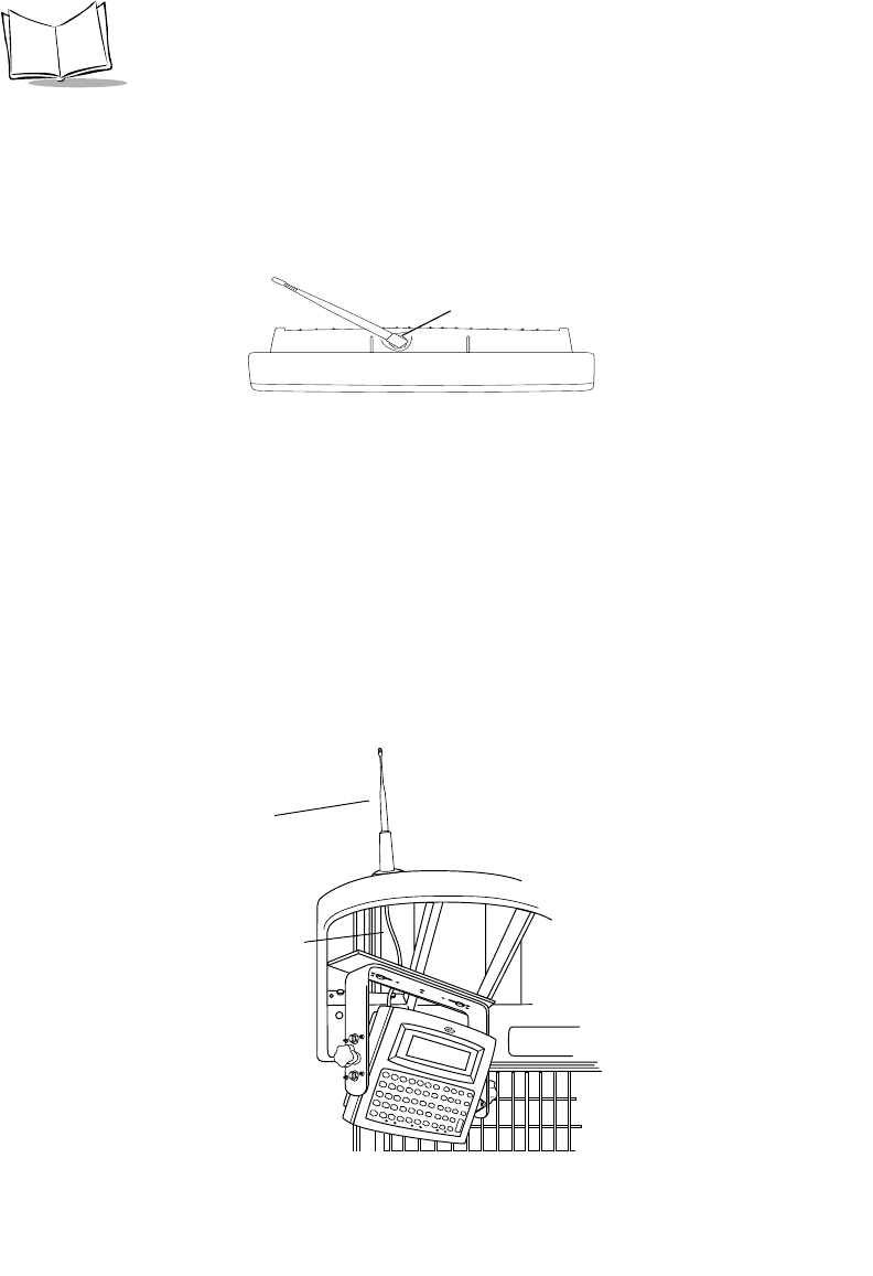
4. Optional: attach a primary antenna to the connector at the top of the terminal, as
shown in Figure 2-4. To attach the antenna:
a. Place the metal end of the antenna onto the connector.
b. Line up the posts with the connector openings and press down gently.
c. Twist the bottom ring clockwise to lock it into position.
Figure 2-4. Attaching a Primary Antenna
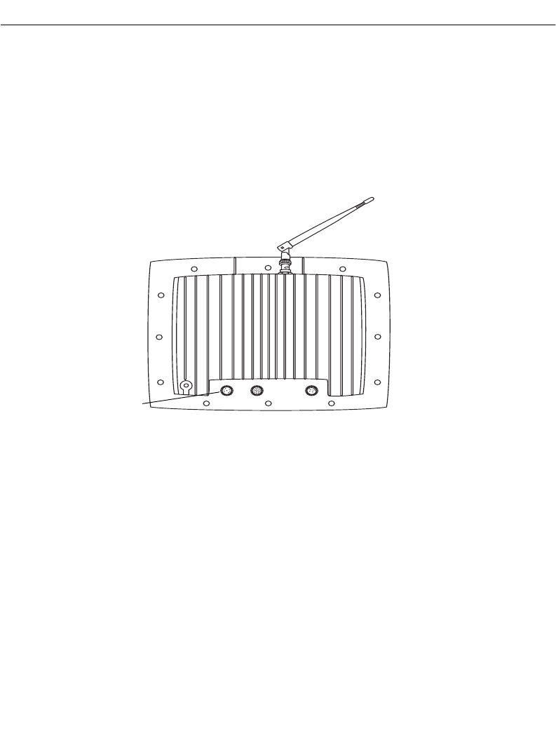
5. Optional: install a vehicle-mounted antenna. Sometimes you can improve wireless
communication by mounting an external antenna onto the vehicle, as shown in
Figure 2-5. Symbol has several different external antennas available. Contact your
Support Representative for more information.
To connect an external vehicle-mounted antenna:
a. Secure the external antenna to an appropriate location on the vehicle.
b. Connect one end of a coaxial cable to the terminal’s Antenna Connector. Connect
the other end to the vehicle-mounted antenna. Make the coaxial cable as short as
possible to minimize signal loss.
Figure 2-5. Vehicle-Mounted Antenna
Back of Terminal Antenna Connector
Coaxial Cable
Antenna
2-5
Installing Hardware
Providing Power: Vehicle Installations
VRC 6940 terminals can be powered by:
!12V or 24V gas-powered vehicles
!battery-powered vehicles, up to 60 volts
To provide power to a vehicle-installed VRC 6940:
1. Locate your vehicle’s power source. Always connect a VRC 6940 terminal to a
continuous or unswitched power source.
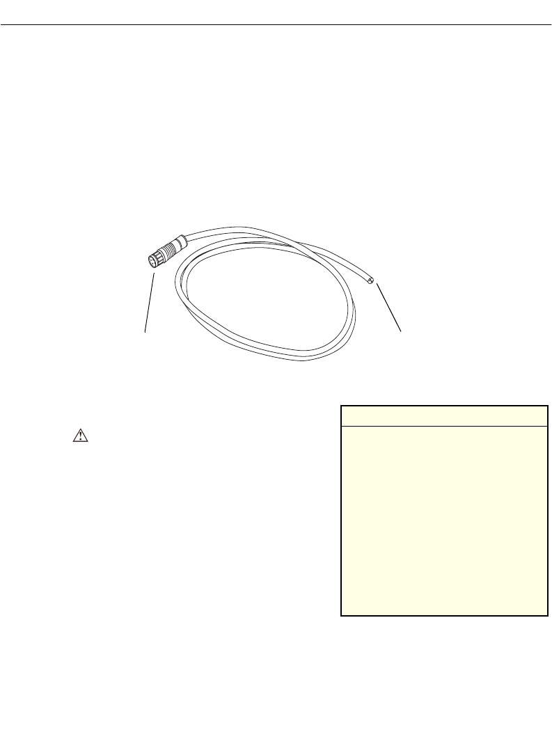
2. Prepare the External DC power cable. One end of the power cable fits into the
terminal’s DC Power connector. The other end has no connector (see Figure 2-6).
Figure 2-6. Preparing the External DC Power Cable
To prepare the External DC power cable end:
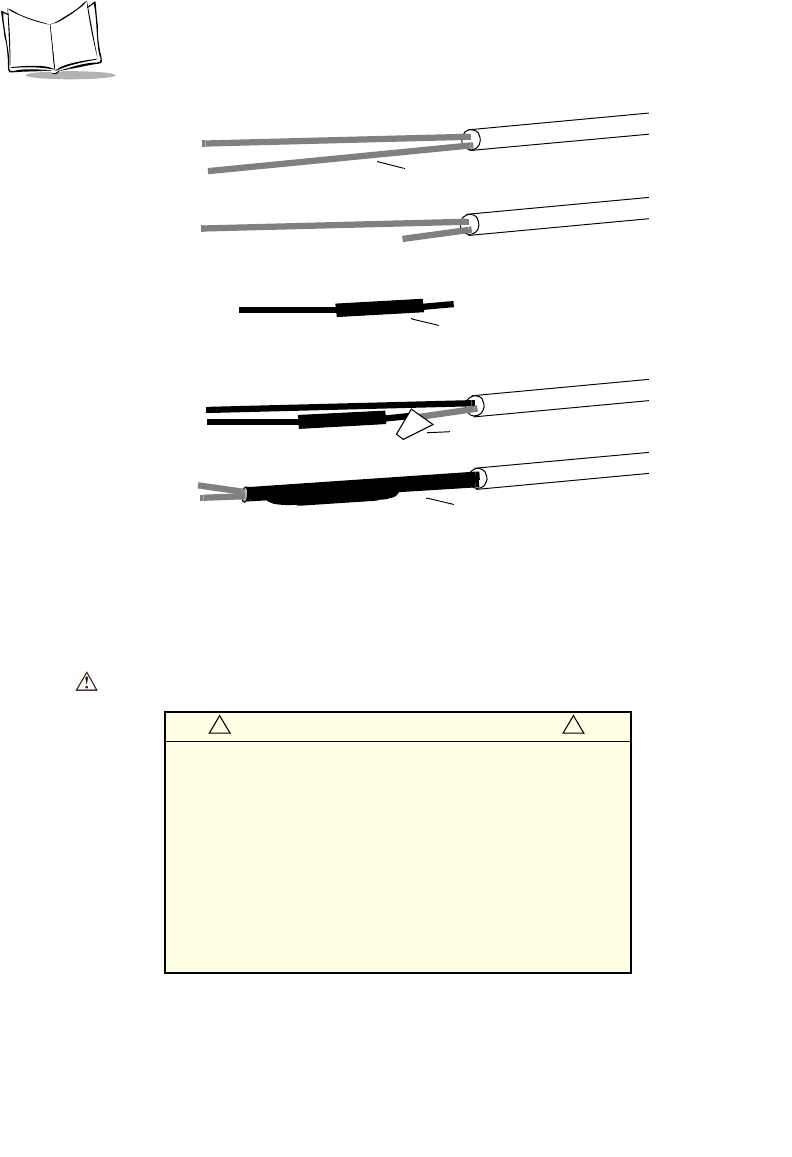
a. In-line fuse holder: if no fused output is
available, add a fuse-holder and 5 Amp
fuse to the External DC power cable.
Follow these steps and refer to Figure 2-7:
i. Strip back six inches of the cable jacket.
ii. Cut about 5” from the red power wire
and strip 3/8” insulation from the wire.
iii. Strip 3/8” insulation from the fuse-
holder wire.
iv. Twist the stripped wire ends together
and splice them using a twist-on nylon
wire connector.
v. Make sure the fuse holder contains a 5 Amp slow-blow fuse. Wrap the wires
neatly, as necessary.
Plug in to the DC Power
Cable End
connector on the terminal
to be prepared
Installation Note: Power Sources
The ideal location for connecting a
VRC 6940 External DC power
cable would be a fused power
source on the vehicle’s power
distribution panel. If no fused
power source is available, connect
the terminal directly to a vehicle
battery. In this case, Symbol
recommends you use an in-line fuse
holder and 5A slow-blow fuse. The
fuse protects your vehicle from an
electrical short on the power cable.
2-6
VRC 6940 Product Reference Guide
Figure 2-7. Adding an In-line Fuse Holder
b. Route the External DC power cable from the terminal location to the connection
point for your vehicle’s power source.
See the Installation Note below.
In-line fuse holder with
5A slow-blow fuse
Twist-on nylon
Wrapped wires
Red power wire
i.
ii.
iii.
iv.
v.
wire connector
and fuse holder
Installation Note: Cable Routing Caution
The means of routing and securing the External DC power
cable from the terminal to the vehicle power source is
extremely important. Hazards associated with improper
wiring can be severe.
To avoid unintentional contact between the wire and any
sharp edges, provide the cable with proper bushings and
clamping where it passes through openings. If the wire is
subjected to sharp surfaces and excess engine vibration,
wiring harness insulation can wear away, causing a short
between the bare wire and chassis. This can start a fire.
! !

2-7
Installing Hardware
3. Prepare the cable termination: Strip 3/8”
of insulation from the two wire ends and
terminate them with a connector that
matches your vehicle’s requirements. See
the Installation Note, right, for more
information.
a. Connect the red wire to the vehicle
power source. Connect the black wire
to a vehicle ground wire or chassis
ground.
b. Connect the External DC power cable
to your vehicle power source.
4. Insert the terminal end of the External
DC power cable into the terminal’s Power
Connector. Align the red dot on the end
of the power cable with the red dot on the Power Connector.
WARNING
A Lead Acid battery can leak Hydrogen gas. A spark anywhere
near the battery can cause it to explode. Always make your final
connection to power as far away from the battery as possible, i.e.,
connect the power cable to the battery first, then connect it to the
terminal.
Providing Power: Wall or Workbench Installations
For wall or workbench-mounted terminals, or for operating a terminal while away from a
vehicle, you can power an VRC 6940 from an AC universal power supply. You need the AC
universal power supply, an AC line cable, and a DC power cable as listed on page 2-1.
To provide power from an AC source:
1. Insert the AC line cable into the AC connector on the AC universal power supply.
2. Plug the other end of the AC line cable into an AC wall outlet.
3. Insert the DC power cable into the DC connector on the AC universal power supply.
4. Plug the other end of the cable into the terminal’s Power Connector.
Installation Note: Cable Termination
How the cable terminates depends on
your vehicle. If your vehicle has a power
output connector, then attach a mating
connector to the end of the power cable.
You may be able to connect to a fuse
panel with a commercially available
connector. If your vehicle has no power
output connector, attach a ring terminal
(for a battery post) or blade terminal
connector (for a fuse panel).
Consult your vehicle Owner’s Manual
for information on how to access your
vehicle’s power supply.

2-8
VRC 6940 Product Reference Guide
Installation and the Internal Battery
A VRC 6940 terminal has an internal battery that powers the terminal if there is a temporary
interruption, disconnection, or fluctuation in the main DC or AC power. We recommend that
you save all data and close all applications before removing a terminal’s main power supply.
You cannot use the internal battery to operate the terminal.
A terminal’s internal battery may be depleted when you first install it. It charges itself from
the terminal’s main power supply (DC or AC). If the main power supply is stable, you can
plug in the terminal and use it immediately.
If the main power supply is not stable, there may be power interruptions that cause the
terminal to reset itself during its first few hours of operation. If the terminal resets itself, you
may lose unsaved data. To avoid this, we recommend that you plug in the terminal and allow
it to charge for two hours before using it.
It takes 48 hours to fully charge the internal battery. A fully charged internal battery can
maintain data for up to 72 hours if the unit is disconnected from its main power source. This
time is reduced if the radio mode maintains continuous communication with a host.
Note: Reliable terminal operation during power interruptions cannot be
guaranteed without a fully charged internal battery. If the internal
battery is not fully charged, a power interruption may cause the
terminal to reset itself and erase valuable data.

3-1
Chapter 3 Configuring Spectrum24
Each VRC 6940 terminal has a Spectrum24 radio card that must be configured before the
terminal can communicate with a Spectrum24 network. This chapter describes how to do
this. For more information on Spectrum24 radio communications, see Spectrum24 Network
Terminal Technical Reference Guide — Radio Firmware and Driver Guide Version 3 (p/n 70-
20193-XX).
Before you begin, read the procedures in this chapter all of the way through and provide a
power source as described in Chapter 2.
Equipment Required
To configure the terminal and transfer applications, you need these items:
!a VRC 6940 terminal
!a reliable power source
3-2
VRC 6940 Product Reference Guide
Configuring a Spectrum24 Radio Card
To configure a Spectrum24 radio card.
1. Provide a reliable power source.
If you have not already done so, install the terminal hardware and provide a reliable
power source as described in Chapter 2. If the terminal is mounted in a vehicle, it can
remain mounted as long as the internal battery is fully charged (see page 2-8) and
you can position it close enough to the host PC for the cables to reach. Otherwise,
remove it from the vehicle, position it on a workbench and provide operating power
with a Symbol AC universal power supply.
Note: If there is a power interruption during configuration, simply restore
the power and start again at step two (Start the Terminal).
2. Start the terminal.
The first time you power up a VRC 6940 terminal, press the ON/OFF key to start
the terminal, and let it run through a series of messages. The terminal loads essential
utilities and system drivers and displays the CFG24 Configurator utility as shown in
Figure 3-1.
You can also start the CFG24 Configurator utility by typing CFG24 at a DOS
command line and pressing ENTER.
Figure 3-1. The CFG24 Configurator Utility
CONFIGURATOR X.XX
View config
ESS Id
Subnet Mask
Default Router
MU IP Address
Diversity
CLR, Enter
^
^
3-3
Configuring Spectrum24
3. Set Spectrum24 configuration
parameters.
The CFG24 Configurator utility lets
you set Spectrum24 parameters in a
text file on the RAM disk
(D:\net.cfg). It also saves the
parameters in a buffer in flash memory
on the radio card. The radio driver and
TCP/IP stack get their configuration
parameters from net.cfg.
Table 3-1 summarizes Spectrum24
parameters. For more information on
setting parameters, see CFG24
Configurator Utility on page A-12.
Table 3-1. Spectrum24 Configuration Options
Option Description
View Config Displays the current Spectrum24 configuration.
ESS Id or Net Id A radio network ID that lets you differentiate between different radio
networks. All equipment on one network must use the same ESS Id or Net Id.
Set this parameter to the same value specified for the Spectrum24 Access
Points (APs). An ESS Id requires a 32-character alphanumeric value. A Net
Id requires a three-character hexadecimal value (101 to 1FE).
Subnet Mask The network uses a Subnet Mask to determine whether or not one device can
communicate directly with another (e.g., a terminal trying to communicate
with a host computer). The Subnet Mask depends on your facility’s IP address
allocations. Set this option as advised by your Network Administrator. The
default value is 255.0.0.0
Note: If you change the boot mode, the value set by a server overrides this
value. See Boot Mode.
Default Router The Default Router is the node address that receives all packets destined for
remote networks. Set this as advised by your Network Administrator. The
default value is 0.0.0.0
MU IP Address If a terminal is using a fixed IP address, enter it in this field. Networks use IP
addresses to determine where to send data that is being transmitted over the
network.
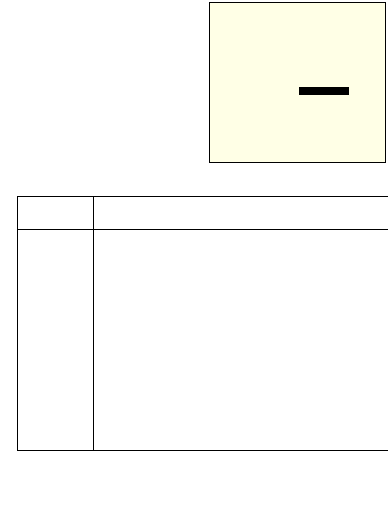
Configuration Note: Navigating the Menus
To navigate through the menus:
•Press UP or DOWN arrow keys to scroll
through menu options.
•To select, highlight the menu option you
want, then press ENTER. A highlighted
option shows up in reverse video .
•To erase an entire entry, press CTRL, and
then D.
•To erase part of an entry, press BACK.
•To return to a previous menu, press
CLEAR.
•To exit to the DOS prompt, return to the
Configurator menu and press CLEAR.
reverse video

3-4
VRC 6940 Product Reference Guide
Note: If you are using a Spectrum24 card with the 802.11 protocol, the ESS
Id option appears on the menu. If you are using a Spectrum24 card
with the Spring protocol, the Net Id option appears on the menu.
Diversity Determines how many antenna ports the radio will attempt to use for
communications. Match this setting to the number of antennas you’re using.
MU Sleep Mode If you set MU Sleep Mode to On, the radio stays on even if an application
powers down the terminal because of inactivity. The default setting is On.
Boot Mode Indicates the source of the terminal’s IP address. Options are Boot, DHCP or
Manual Entry. If you select Manual Entry, the terminal uses the IP address
specified in MU IP Address. See page A-17 for more information.
Pwr Management If you set Pwr Management to PSP, the radio only powers up when there is
traffic on the network. If you set it to CAM, the radio is always ready to
receive. The default setting is PSP.
Buffers Sets the number of data buffers used by the radio driver (4, 8 or 12).
ReXmit Delay If a terminal tries to transmit a packet and fails, it tries to re-transmit the
packet later. ReXmit Delay sets the length of time between re-transmissions.
The options are short and long. The short option improves response time but
uses more power. If there is high network traffic, or a high amount of
electrical “noise” nearby, select short to improve response time.
Rate Control Determines which Spectrum24 Access Points a terminal can communicate
with. The options are 1Mb only, 2Mb only, 1Mb and 2 Mb. Select a
parameter that matches the Rate Setting for the AP, if one has been specified.
For more information see Spectrum24 Wireless LAN Adapter Product
Reference Guide (p/n 70-20505-XX).
Scan/RF Op Determines whether or not the scanner and radio can operate at the same
time. Concurrent Op allows both to operate at the same time. Scan Stops RF
causes the scanner to lock out the radio during an active scan.
Exit Closes the utility and displays a DOS prompt.
Table 3-1. Spectrum24 Configuration Options
Option Description

3-5
Configuring Spectrum24
4. When you finish setting Spectrum24 parameters, warm boot the terminal:
a. Press the ON/OFF key to suspend the terminal.
b. Press and hold the SHIFT and L keys.
c. Press and release the ON/OFF button.
d. Release the SHIFT and L keys.
"The terminal reloads the system drivers and attempts to associate with a
Spectrum24 AP.
"If the radio card is configured correctly, it tries to locate a bootp server, fails, and
boots to a DOS prompt. This means the radio card is working correctly. Proceed
to step 5.
"If the radio card is not configured correctly, the CFG24 Configurator utility
reappears. Recheck your configuration parameters and perform another warm
boot.
5. Turn the VRC 6940 off.
You have successfully configured the Spectrum24 radio card. You may now
download and install application programs. See Transferring and Installing
Application Programs on page 4-2.

3-6
VRC 6940 Product Reference Guide

4-1
Chapter 4 Installing Software
This chapter describes how to install application programs onto a terminal. VRC 6940
terminals have a number of drives available for storing user applications and data. For more
information on available drive space, the software environment and a list of standard VRC
6940 software, see Appendix B, Software Environment.
Before you begin, read the procedures in this chapter all of the way through.
Equipment Required
To transfer applications, you need:
!a VRC 6940 terminal
!a Host PC
!an RS-232 serial null modem cable with a 16-pin male connector at one end, and a
25-pin female connector at the other end
!a reliable power supply
!software for transferring files from a Host PC to the terminal
See Tab le 4-1 for information on recommended software. Also see the Series 3000
Application Programmer's Reference Manual (p/n 70-16309-XX).
Table 4-1. Software Required for Transferring Files
Type of File to be Transferred Host PC Software VRC 6940 Software
HEX Image SENDHEX or WINHEX Program Loader
Other file types TFT3000 TDREM
4-2
VRC 6940 Product Reference Guide
Transferring and Installing Application Programs
This section describes how to transfer a HEX image from a Host PC onto a VRC 6940
terminal over a standard RS-232 null modem cable. The procedure uses the SENDHEX or
WINHEX program on the Host PC and the Program Loader utility on the VRC 6940.
The Program Loader installs the HEX image by converting the ASCII data stream into files
that are stored in non-volatile memory (NVM) on the terminal (the application EEPROM).
Any further installation procedures depend on the contents of the HEX file.
To transfer non-HEX images or files, use the TFT3000 program on the Host PC, and the
TDREM utility on the terminal. For details on all of these programs, refer to the Series 3000
Application Programmer’s Reference Manual (p/n 70-16309-XX).
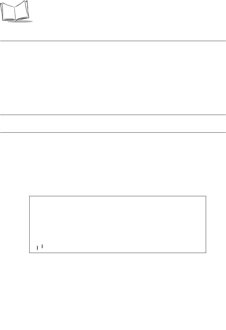
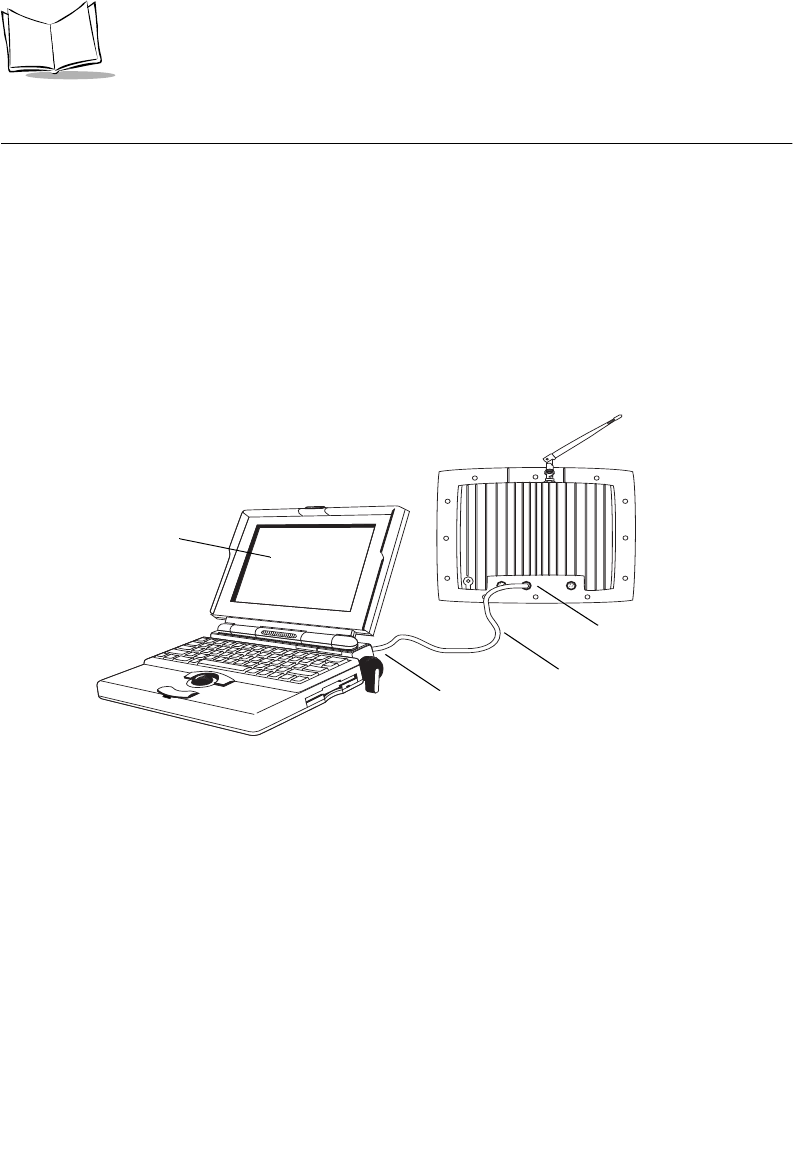
Figure 4-1. Cabling for Downloading on Benchtop
1. Prepare the PC for Communications and File Downloading
To prepare the PC for communications:
1. Begin with the VRC 6940 terminal in suspend mode.
2. Remove the plug cover from the RS-232 serial port on the terminal, and attach the
male connector end of the null modem cable.
3. Attach the female end of the null modem cable to the Host PC serial port, as shown
in Figure 4-1. Use an adapter, if necessary.
4. On the PC, start the communications program. For example, to use SENDHEX, first
open a DOS window. Then type the SENDHEX command with appropriate
To the serial port
VRC 6940 RS-232
serial port
Null modem cable
Laptop Computer

4-3
Installing Software
parameters, and press ENTER. The example in Figure 4-2 shows a baud rate of
38400, and the COM2 option. For pgmname, type the name of the HEX file you are
transferring, without the .hex extension. The default parameter values are:
"9600 bps
"COM1
"7 data bits
"Odd parity
"Xon/Xoff flow control
Figure 4-2. Setting up Communications with SENDHEX
Note: Versions of SENDHEX earlier than version 3.0 do not support flow
control. If you are using an earlier version, and errors appear, use a
lower baud rate.
5. A prompt appears as shown in Figure 4-3. Do not press ENTER yet. You must set
up the VRC 6940 terminal next, as described in the next section.
Figure 4-3. The SENDHEX Prompt
C:\>cd\
sendhex pgmname 38400 com2
SENDHEX HEX File Name
(no .hex extension) Baud Rate
COM Port
Command
C:\>cd\
sendhex pgmname 38400 com2
Version: 3.01-01
Press <Enter> when remote is ready. ESC to abort...
4-4
VRC 6940 Product Reference Guide
2. Provide a Reliable Power Source
If you have not already done so, install the terminal hardware and provide a reliable power
source, as described in Chapter 2. If the terminal is mounted on a vehicle, it can remain
mounted as long as the internal battery is fully charged (see page 2-8) and you can position
it close enough to the Host PC for the cables to reach. Otherwise, remove it from the vehicle,
position it on a workbench and provide operating power with a Symbol AC Universal Power
Supply.
Note: If there is a power interruption during the file transfer process, restore
the power and start again at step three (Prepare the Terminal for
Transferring Files).
3. Prepare the Terminal for Transferring Files
This section describes how to run the Program Loader utility on a VRC 6940 terminal, so the
terminal can receive files transferred from a Host PC. To set up the terminal:
1. Boot the VRC 6940 into Command Mode:
a. With the terminal in suspend, press and hold
the A and D keys.
b. Press and release the ON/OFF key.
c. Release the A and D keys.
2. The terminal boots to the Command Mode
screen, shown in Figure 4-4.
Figure 4-4. Command Mode screen
Installation Note: Using Menus
To navigate the menus:
•Press UP or DOWN arrow
keys to scroll through options.
•To return to the previous
menu, press CLEAR.
COMMAND MODE
Select Function
Self Test

4-5
Installing Software
3. Press UP or DOWN arrows to scroll through Command Mode options until you see
the Program Loader option. Then press ENTER to display the message shown in
Figure 4-5.
Figure 4-5. Erasing NVM (EEPROM)
4. When you are ready to erase
EEPROM, press ENTER. This
message appears:
Program Loader
Erasing EEPROM
Please wait....
The program erases the EEPROM
and prompts you for communications
parameters.
5. Set the communications parameters to 38400 bps, 7 data bits, odd parity and
Xon/Xoff flow control.
a. Baud Rate: Select 38400. The screen will look like this:
Figure 4-6. Setting Baud Rate on the VRC 6940
Program Loader
WARNING: EEPROM
WILL BE ERASED
CONTINUE? <ENT>
Installation Note: Before you Erase EEPROM
If you have not configured the Spectrum24
radio card for the terminal, press CLEAR to
cancel the operation, and configure the radio
card now (see page 3-2). When you run the
Program Loader and press ENTER, it erases
the EEPROM (non-volatile memory). You
must erase the EEPROM before you can
transfer the HEX file onto the terminal.
Comm Parameters
Baud
6 38400

4-6
VRC 6940 Product Reference Guide
b. Data Bits: Select 7. The screen will look like this:
Figure 4-7. Setting Data Bits on the VRC 6940
c. Parity: Select Odd. The screen will look like this:
Figure 4-8. Setting Parity on the VRC 6940
d. Flow Control: Select Xon/xoff. The screen will look like this:
Figure 4-9. Setting Flow Control on the VRC 6940
6. When all parameters are set, the screen displays this message:
Program Loader
Start? <ENT>
7. Press ENTER to start the Program Loader.
Comm Parameters
Data Bits
7
Comm Parameters
Parity
Odd
Comm Parameters
Flow Control
Xon/xoff

4-7
Installing Software
4. Start the File Transfer
1. On the Host PC, press ENTER to start the transfer. The Host PC displays this
message:
C:>\ Bytes sent = xxxx xx%
If the Host PC is not ready or the cable is disconnected between the PC and the
terminal, the PC displays this message:
Awaiting DSR
In this case, check the cable connection and then press ENTER again on the Host PC
to start the download.
2. During the transfer, the VRC 6940 terminal displays these messages:
Program Loader
Receiving :xxxx
Check the status on both the terminal and the Host PC during data transmission.
They should both show program segment addresses being transferred (XXXX). If
this does not happen, then the data is not transferring correctly.
3. When the transmission is complete, the terminal displays a status code. A successful
download shows a status of 0000. This message appears:
Program Loader
Status 0000
Any other value indicates a failed transfer. See Appendix E, Communications Status
Codes.
Failed Transfers
If a file transfer finishes with a status value other than 0000, then the transfer was not
successful. In this case:
1. Check cable connections between the VRC 6940 terminal and the Host PC. Make
sure the null modem cable is connected to the correct port on the Host PC.
2. Repeat the transfer steps using a lower baud rate (e.g., 19200).
3. If the problem persists, contact Symbol Technical Support for assistance.

4-8
VRC 6940 Product Reference Guide
Successful File Transfer
Following a successful file transfer, the files must be copied to the flash disk before you can
use them. This happens the next time the terminal is re-initialized (cold booted). See
5. Complete the Installation of Transferred Files, next.
5. Complete the Installation of Transferred Files
To complete the installation of transferred files, you must re-initialize (cold boot) the
terminal. To do this:
1. Disconnect the null modem cable from the VRC 6940 terminal and Host PC.
2. Replace the terminal plug cover for the serial port on the VRC 6940.
3. Perform a cold boot:
a. Press and hold the ENTER, F1 and F4 keys.
b. Press and release the ON/OFF key.
c. Release the ENTER, F1 and F4 keys.
4. When the terminal restarts, it boots according to the applications you have loaded.
For more information, refer to the documentation for the applications.

5-1
Chapter 5 Operating a VRC 6940
After you install and configure a VRC 6940 terminal for your facility, you can release it for
use. This chapter describes how to use the terminal, including:
!Powering the terminal On and Off
!Resetting the terminal
!Adjusting brightness
!Entering data
!Attaching a scanner
!Moving a terminal to different power source
!Booting into Command Mode
The instructions in this chapter assume that the terminal has been fully installed, configured,
and set up to run your facility’s software applications. For information on installing and
configuring a terminal, see Chapters 2, 3 and 4.
5-2
VRC 6940 Product Reference Guide
Powering a Terminal On and Off
A terminal must be connected to a main power supply (e.g., a vehicle battery). If you remove
this power supply, the terminal suspends and cannot be turned on again until you reconnect
the power. An internal battery maintains data while the terminal is suspended, but it cannot
be used to operate the terminal. Save all your data and close all applications before removing
a terminal’s main power supply. See page 2-8 for more information.
Powering On
To turn the terminal on, press the ON/OFF key located at the top right corner of the alpha
section of the keyboard. As the terminal starts, several screens of information appear,
followed by the application screen set to run at your facility. If the terminal does not power
on, see Chapter 6, Troubleshooting.
Figure 5-1. The ON/OFF key
Suspending or Turning Off the Terminal
To suspend the terminal, press the ON/OFF key. The terminal appears to turn off. However
if you press the ON/OFF key again, the terminal resumes its previous session.
Forcing the Terminal into Suspend
If the terminal does not suspend when you press the ON/OFF key, you can force it into suspend.
To do this, press and hold the ON/OFF key for 15 seconds, or until the display goes dark.
Turning the Terminal Off
Normally, you will not turn the terminal off: you will place it into suspend. The terminal only
turns off if you have:
!disconnected the power cable, AND
!allowed the internal battery to run down.
For more information, see Installation and the Internal Battery on pa g e2-8.
To start the terminal press the ON/OFF key.

5-3
Operating a VRC 6940
Powering On or Off Automatically
Particular applications may cause a VRC 6940 to power on or off automatically. This can be
controlled by application programming or default configuration settings. For example, some
applications may cause the system to be powered on by:
!pressing a key other than the ON/OFF key
!pressing a scanner trigger
!scheduled, unattended operations such as an overnight communications session
The terminal may also power OFF automatically:
!as triggered by an application.
!if it is not used for some period of time determined by settings in the application you
are using. For more information, see the documentation for your application.
Resetting a Terminal
You cannot reset the system or applications on a VRC 6940 by pressing the ON/OFF key.
When you press the ON/OFF key to suspend a terminal, it maintains its current session and
session data. When you turn it on again, it restores the display and continues processing from
the point where it was when you powered down.
To reset the system and applications, you must reset the terminal. You may need to reset a
terminal if:
!the power has been forced off.
!the terminal stops responding to keystrokes or to the ON/OFF key.
!you need to end the current session and start a new session.
To reset (warm boot) a terminal:
1. Press the ON/OFF key to suspend the terminal. If necessary, force it into suspend by
pressing and holding the ON/OFF key for 15 seconds.
2. Press and hold the SHIFT and L keys.
3. Press and release the ON/OFF key.
4. Release the SHIFT and L keys.
The terminal restarts and you can log in to an application. Note that if you reset a terminal,
you may lose any unsaved data.
5-4
VRC 6940 Product Reference Guide
Modifier Keys: SHIFT, FUNC and CTRL
SHIFT, FUNC, and CTRL are modifier keys that generate a special character or function. For
example, you might press FUNC, J to brighten the display. To do this:
1. Press and release the FUNC key.
2. Press and release the J.
3. The display brightens and the keyboard returns to normal functioning.
Use modifier keys individually or in combinations. For example:
!Press SHIFT to cause the next alpha key press to generate an upper case letter.
!Press FUNC, and then CTRL to generate an ALT function, just like the ALT key on
a PC.
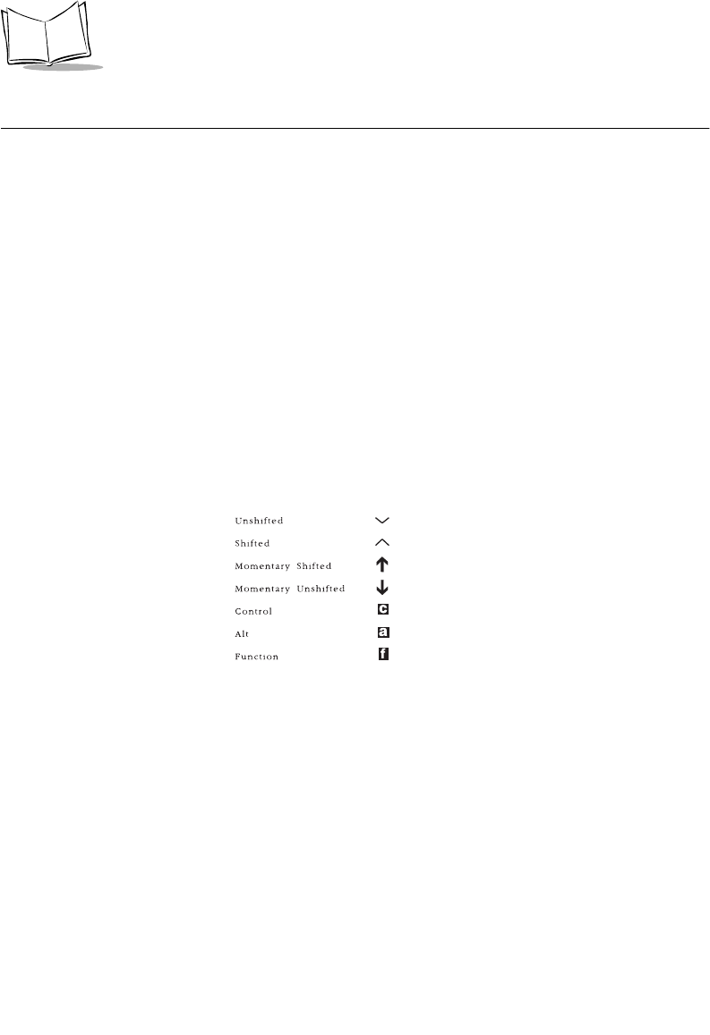
The shape of the cursor displayed on the screen indicates the state of the keyboard. Figure 5-
2 shows what the standard cursor shapes mean. Note than an application can modify the
standard keyboard cursor shape.
Figure 5-2. Keyboard State Cursor Indicators
Key Descriptions
Most of the keys are self-explanatory: alpha keys produce alpha characters, number keys
produce numeric characters. Table 5-1 describes special functions performed by specific keys
and key sequences. For additional information on keyboard characters and layouts, see
Appendix C, Keyboard Layouts.
Keyboard
State Cursor
Character Low
Battery

5-5
Operating a VRC 6940
Table 5-1. Special Key Sequences
Tips for Using the Keyboard
"Press only one key at a time, unless instructions specifically tell you to press two
keys at the same time (e.g., when resetting the terminal). Pressing two or more
keys at the same time can cause an error.
"Press keys in the correct sequence. If an applications lists keys in a sequence, press
the keys one at a time in the order they are listed.
"Auto-repeat feature. Some applications use the configurable auto-repeat feature
of the keyboard. If they do, when you press and hold a key, the character will
repeat until you release it.
If a key is pressed immediately after a modifier key, the modifier sequence affects
only the first occurrence of the character key. For example, if you press SHIFT,
and then press and hold A, the terminal generates: Aaaaa.
Function Access
Method
Description
SHIFT SHIFT key After you press SHIFT, the next key you press appears in
uppercase (for an alpha key), or as a punctuation mark or
symbol (for a number key).
CAPS LOCK FUNC, L Places the whole keyboard into Caps Lock mode. Press FUNC,
L again to cancel this feature.
FUNC FUNC key A function key used to invoke special keyboard functions.
CTRL CTRL key A control key used to generate control characters.
ALT FUNC, CTRL Generates an Alt key function similar to the one found on a PC.
Invokes special keyboard functions.
F1 to F5 F1 to F5 keys Function keys F1 to F5. Their actions are controlled by
application programs.
F6 to F10 FUNC, F1 to
FUNC, F5
Function keys F6 to F10. Their actions are controlled by
application programs.
ENTER ENTER key Usually pressed after typing data or a command.
CLEAR CLEAR key This key is controlled by applications. It usually allows you to
escape from an application or screen, or clear the data entered
in a field.
Darken Screen FUNC, I Press to dim the display contrast.
Brighten Screen FUNC, J Press to brighten display contrast.
5-6
VRC 6940 Product Reference Guide
Adjusting Brightness
Entering Data
To enter data or issue commands, use the terminal’s keyboard, or attach a scanner (see Figure
5-4).
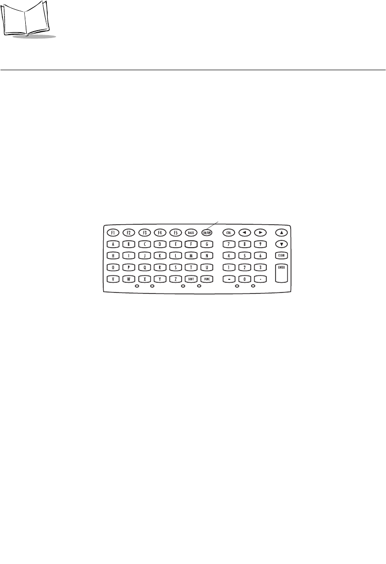
Using the Keyboard
Use the VRC 6940 keyboard to enter data and perform other tasks. The keyboard includes
character keys (A - Z, 0 - 9), and modifier keys, described on page 5-4. When used in
combination with one or more modifier keys, each character key can produce more than the
usual one or two characters.
Figure 5-3. VRC 6940 Keyboard
Task Key Sequence Comment
Brighten the screen. FUNC, J There are seven levels of brightness.
Repeat the key sequence to reach the
desired level of brightness.
Darken the screen. FUNC, I
Toggle the keyboard
backlight on or off.
FUNC, K Not all terminals include a keyboard
backlight option.
5-7
Operating a VRC 6940
Bar Code Scanning
Attaching an External Bar Code Scanner
1. Press the ON/OFF key to suspend the terminal.
2. Remove the plug cover from the scanner port on the back of the terminal, shown in
Figure 5-4.
3. Fit the scanner’s connector plug into the connector. Align the red dot on the end of
the scanner cable with the red dot on the terminal’s scanner connector.
4. Press the ON/OFF key to power the terminal on.
Figure 5-4. Scanner Port
Using a Bar Code Scanner
For information on using a bar code scanner, consult the documentation that came with the
scanner.
Scanner Port
Back of Terminal

5-8
VRC 6940 Product Reference Guide
Moving a Terminal to a Different Power Source
To move a VRC 6940 terminal from one power source to another:
1. Save any data you are working with, and close all applications.
2. Press the ON/OFF key to suspend the terminal.
3. Make sure a power source is ready in the new location.
4. Unplug the external power cable from the power connector on the back of the
terminal.
5. Remove the terminal from its current mounting.
6. Move the terminal to the new location and mount it.
7. Plug the external power cable into the power connector. Align the red dot on the end
of the power cable with the red dot on the terminal’s power connector.
8. Press the ON/OFF key to restart the terminal.
Command Mode
Command Mode is an operating mode that allows you to use the terminal’s built-in system
utilities. For example, you can use it to:
!run Self-Test diagnostics to verify that the hardware is operating properly (see
Appendix B)
!transfer data, hex images or files from a host system to a VRC 6940 (see Chapter 4)
To boot to Command Mode:
1. Press the ON/OFF key to suspend the terminal.
2. Press and hold the A and D keys.
3. Press and release the ON/OFF key.
4. Release the A and D keys.
5. This menu appears on the terminal display:
COMMAND MODE
Select function
Self test
6. Press UP or DOWN arrows to display different options. When the option you want
appears, press ENTER to select it.

6-1
Chapter 6 Troubleshooting
This chapter provides basic problem-solving information for VRC 6940 terminals, including:
!troubleshooting and error messages
!warm and cold boot instructions
!running the Memory Transfer utility to provide more troubleshooting data
Troubleshooting a VRC 6940 Terminal
Table 6-1 describes some problems, their probable causes and some suggested solutions.
Some of the situations are discussed further in the pages that follow.
Table 6-1. Troubleshooting VRC 6940 Terminals
Problem Action
Terminal does not start Make sure the terminal is connected to a power source. If the external
power cable has come unplugged, plug it back in and press the ON/
OFF key to restart the terminal.
Whether or not your session and data were saved depends on the
internal battery and how long the terminal was disconnected. If the
internal battery has not been depleted, the session will resume where
it left off. See page 2-8 for more information on the internal battery.
If the terminal uses a vehicle battery as a power source, check the
vehicle battery. If it is depleted (dead), replace the vehicle battery.
Terminal suspends suddenly
(shuts off)
The terminal suspends if it loses the connection to its main power
source. Check the main power supply and power cable. You should be
able to restart the terminal when you reconnect to a power source.
Whether or not your session and data were saved depends on the
internal battery and how long the terminal was disconnected. See page
2-8 for more information on the internal battery.

6-2
VRC 6940 Product Reference Guide
Start-up process fails The terminal may be out of range of the Access Point (AP) and unable
to communicate with the host computer. Move the terminal closer to
the AP and try starting it again.
If one of these messages appears:
Boot server doesn’t exist.
Boot server not configured for this terminal.
1. The bootp server may not be running. Check the bootp server.
2. The radio may not be functioning. Ping test the terminal (see page
A-5).
Power fault This message may appear if the last terminal shutdown was caused by
a power failure. The message blinks in place for three seconds, then
the terminal starts normally. A power failure can be caused by:
•unplugging the terminal’s power cable when the internal battery is
not fully charged
•removing the vehicle battery
•sudden main battery failure
If the internal battery is charged, it can maintain session data and your
session will resume when you restore the main power source. If the
internal battery is depleted the terminal cannot maintain session data,
and you may lose unsaved data. See page 2-8 for more information on
the internal battery.
Display is blank The terminal may not be getting power. Make sure the power cable is
securely connected to a reliable main power source (vehicle battery or
AC) and to the Power Connector on the terminal.
An application program did not download successfully.
Repeat the download process using the procedures described in
Transferring and Installing Application Programs on page 4-2.
The display may be damaged or the video connector may be loose.
Return the unit for servicing.
Scanner does not operate Check to make sure the scanner is properly connected to the terminal.
Re-connect the scanner and then reboot the terminal.
Check the documentation for the scanner you are using.
Table 6-1. Troubleshooting VRC 6940 Terminals
Problem Action

6-3
Troubleshooting
Error Messages
The terminals use ERR3000.SYS, a factory-installed program that displays error messages.
Messages blink in place on the display screen for three seconds. The terminal beeps while the
message is showing. Then the system returns to its previous status. Table 6-2 lists some
sample messages. Application programs can change or disable messages. For more
information, refer to the Series 3000 Application Programmer’s Guide (p/n 70-16308-XX).
Table 6-2. Error Messages
Scanner laser works but does
not read bar codes
The bar code may not be legible. Try scanning another label of the
same product, or type in the data manually.
The scanner window may be dirty or severely scratched.
If it is dirty, clean it with a soft, dry cloth moistened with an ammonia-
based glass cleaner. If the scanner window is badly scratched, replace
the scanner.
The scanner may not be programmed or may be programmed
incorrectly. Consult the reference guide that came with the scanner for
configuration information.
Application does not
respond
This can happen if the terminal cannot connect to the Access Point
(AP). If the terminal cannot connect to the AP, applications may
continue to function until they need to transmit to the AP, then they
simply stop responding.
The terminal may be out of range of the AP. Move the terminal to a
location closer to an AP and then try to restart it. See page 6-4 for
more information.
The host computer may be down. Check the host computer.
There may be a problem with the application software. Do a Memory
Transfer to transmit data from the VRC 6940 terminal to a Host PC,
and have an application programmer examine the data. See page 6-8.
Message Explanation
Double Key Error You have pressed two keys at the same time. This message does not appear for
the warm, cold, and Command Mode boot sequences described on page 6-5.
Too Many Keys Three or more keys have been pressed at the same time.
Power Fault The last power off was caused by a power failure. This occurs, for example, if
power suddenly fails or is disconnected. For more information, see Tabl e 6- 1.
Table 6-1. Troubleshooting VRC 6940 Terminals
Problem Action

6-4
VRC 6940 Product Reference Guide
Scanning Problems
Scanning may not work correctly if:
!the scanner has not been configured, or is configured incorrectly
!a contact wand scanner has been moved over the bar code too slowly, too quickly or
at an uneven speed
!a contact wand scanner has been moved diagonally across the bar code
!a bar code scanner was held at the wrong angle or distance from the bar code
!the scanner window is dirty or severely scratched
!labels are smudged
!labels are too dark, too light, or have poor color contrast
!labels have highly reflective surfaces or coatings
!labels are torn, folded, or wrinkled
For more information, consult the documentation for your scanner.
Terminal Stops Responding
This section describes what to do if a VRC 6940 terminal stops responding during a session.
1. Make Sure You are Within Range of an Access Point
If you have moved the terminal during use, make sure you are still within range of an Access
Point (AP). Move back to a previous working location or to a location closer to the AP to see
if it responds. See page 6-5 for information on checking Radio Connection status.
2. Force the Terminal into Suspend
If you are within range of an AP, and the terminal is not responding, force the terminal into
suspend and then restart it using the instructions below. To force the terminal into suspend
without resetting it, press and hold the ON/OFF key for 15 seconds.

6-5
Troubleshooting
3. Restart After Forcing a Suspend
If you have forced the terminal into suspend, do not use the ON/OFF key to restart the
terminal, as this causes the program to resume where it left off, trying to perform the same
unsuccessful operation.
1. First, try to start the terminal with a warm boot, described on page 6-5.
2. If a warm boot does not correct the problem, try a cold boot, described on page 6-6.
3. If a cold boot does not correct the problem, try to boot into Command Mode,
described on page 6-7.
4. If you cannot boot into Command Mode, contact Symbol Technical Support.
Booting a VRC 6940
Warm Boot
A warm boot resets the operating system and software while preserving the program and data
that may be on the RAM disk. To perform a warm boot:
1. Press the ON/OFF key to suspend the terminal.
2. Press and hold the SHIFT and L keys.
3. Press and release the ON/OFF key.
4. Release the SHIFT and L keys.
The VRC 6940 displays copyright, RAM size, expanded memory size, and other
start-up information, depending on the system's configuration.
If a warm boot successfully solves the problem, then the problem may have been caused by:
!an error in the application program
!a temporary communications problem in the network
Consider going back into the application that was running when the problem occurred, and
try to recreate the problem. If there are network problems during the boot process, the
terminal may display a message similar to this one:
NOT ASSOCIATED
and a DOS prompt appears. From here, use the DIAG24 software to run ping tests or identify
potential radio problems on the network. See page A-5.

6-6
VRC 6940 Product Reference Guide
Cold Boot
A cold boot fully resets the system and clears memory, including the RAM disk. It resets the
software and allows you to restart applications. Any unsaved RAM data will be lost.
Programs and data that have been stored in memory or on the RAM Disk are deleted. Non-
Volatile Memory (NVM) is not affected. To perform a cold boot:
1. Press the ON/OFF key to suspend the terminal.
2. Press and hold the ENTER, F4 and F1 keys.
3. Press and release the ON/OFF key.
4. Release the ENTER, F4 and F1 keys.
The VRC 6940 displays a copyright message, amount of RAM, and amount of
expanded memory. Other messages are displayed as well, varying with the system
configuration.
As the terminal boots, watch for cold boot failure messages. You may need to
reinstall a device driver. See Cold Boot Failure Messages, below.
5. Follow the instructions in Chapter 4, Installing Software to reinstall software.
Caution
The cold boot procedure erases all data and programs residing on the RAM
Disk. All contents of the RAM disk are lost.
If you have had problems starting the terminal, and cold booting (clearing memory) allows
you to boot the terminal, then something in memory was causing the problem. Perform a
Memory Transfer (see page 6-8) so that a programmer can perform application-specific
troubleshooting. Then install the correct version of the software as described on page 4-2.
Cold Boot Failure Messages
During a cold boot, the system briefly displays a status line for each driver as it loads, in this
format:
0: Drivername #.##
The line shows a status value, usually 0, followed by the driver’s name and version number.
If the system halts at one of these lines and displays a status value other than 0, the displayed
device driver failed to load properly. If such a failure occurs, the driver may need to be
reinstalled. Contact Symbol Technical Support.

6-7
Troubleshooting
Command Mode
To boot to Command Mode:
1. Press the ON/OFF key to suspend the terminal.
2. Press and hold the A and D keys.
3. Press and release the ON/OFF key.
4. Release the A and D keys.
This terminal displays this screen:
Figure 6-1. Command Mode screen
5. Use the UP or DOWN arrows to display other options in place of Self Test. When the
option you want appears, press ENTER to select it.
If warm or cold booting do not clear your problem, but you can boot to Command Mode,
the problem may be:
!BIOS and hardware problems: to check the BIOS and hardware, use the Self Test
function to check the system hardware (described on page A-2). If there is a
hardware problem, contact Symbol Technical Support.
!Application program error: if system hardware is running properly, check for an
application error. Perform a Memory Transfer (described on page 6-8) so that a
programmer can perform application-specific troubleshooting. Then install the
correct version of the software as described on page 4-2.
If Rebooting Fails
1. Re-install software following the procedures described in Chapter 4, Installing
Software.
2. Contact your authorized Symbol Support representative or Technical Support
Services.
COMMAND MODE
Select Function
Self Test

6-8
VRC 6940 Product Reference Guide
Memory Transfer Analyzer (MTA) Utility
The VRC 6940 has a Memory Transfer Analyzer (MTA) utility for application
troubleshooting. It runs from Command Mode. Programmers can analyze applications using
RCVHEX.EXE on a PC and the MTA on the VRC 6940. For more information on
RCVHEX.EXE, see the Series 3000 Application Programmer’s Guide (p/n 70-16308-XX).
The MTA transmits data from a VRC 6940 to the Host PC. You may transfer all of the
memory, or a selected range.
Transferring Memory
To transfer memory from a VRC 6940 to a Host PC you will need:
!a Host PC running the RCVHEX.EXE application
!a VRC 6940 running the MTA
!a null modem cable
Note: Always suspend a VRC 6940 terminal before attaching or removing
cables or adapters.
To conduct the Memory Transfer:
1. Start with the VRC 6940 terminal in suspend.
2. Attach the null modem cable.
a. Remove the RS-232 plug cover from the VRC 6940 terminal and plug the male
connector into it.
b. Attach the female connector to the Host PC (see Figure 4-1 on page 4-2), using
an adapter if necessary.
3. On the Host PC, exit to a DOS prompt and start the RCVHEX program. For an
example, see Figure 6-2.
a. For a filename, use an existing file, or create one by supplying the filename in the
command. The example in Figure 6-2 shows a filename of memory.txt.
b. Set the baud rate to match the baud rate for the VRC 6940.
c. Leave Data Bits and Parity set to their defaults.
d. Set the COM port as appropriate for your Host PC.
e. Press ENTER to send the command.

6-9
Troubleshooting
Figure 6-2. Setting up to Receive a Memory Transfer
4. Boot the VRC 6940 to Command Mode:
a. Press and hold the A and D keys.
b. Press and release the ON/OFF key.
c. Release the A and D keys.
d. The terminal boots to the function selector screen in Command Mode, as shown
in Figure 6-3. Press UP or DOWN arrows to scroll through the options.
Figure 6-3. Command Mode Screen
5. When the Memory Transfer option appears, press ENTER.
6. The systems displays this message:
Checking Memory
Please Wait
C:\>rcvhex memory.txt 38.4 1
RCVHEX Filename to receive data
(you can make one up)
Baud Rate COM Port
Command
COMMAND MODE
Select Function
Self Test

6-10
VRC 6940 Product Reference Guide
7. Select a range of RAM to transfer. Press the UP and DOWN arrows to select an
option (All, Range or None) and press ENTER. If you select All, the program
skips to the summary screen. Continue at step 10.
Figure 6-4. Selecting a Range of Memory to Transfer
8. Specify a range of RAM by setting Start and End addresses. Use LEFT and RIGHT
arrow keys to move the cursor to a digit that you want to set. Use UP and DOWN
arrow keys to change the value. When the correct range appears, press ENTER.
Figure 6-5. Selecting a Range of RAM to Transfer
9. Specify a range of NVM to transfer. Use the arrow keys to select All or None, and
then press ENTER.
Figure 6-6. Selecting a Range of NVM to Transfer
RAM
Select Option
All
RAM
Use arrow keys
Start End
00000 9FFFF
NVM
Select Option
All

6-11
Troubleshooting
10. If the VRC 6940 has EMS, use the arrow keys to specify the range to transfer. This
prompt only appears if EMS is installed. Then press ENTER.
Figure 6-7. Selecting a Range of EMS to Transfer
11. The terminal displays the ranges you selected. Verify that they are correct. Figure 6-
8 shows an example of what you might see. If the values are correct, press ENTER.
If the values are not correct, press CLEAR to clear the fields, then select new values.
Figure 6-8. Verifying Memory Transfer Settings
12. Next, the VRC 6940 prompts you to set communications parameters. Use UP or
DOWN arrows to select communications settings. The defaults are 9600 bps, 7 data
bits and odd parity. Xon/xoff flow control may be necessary at 38400 bps. Select the
parameters so that they match those used by RCVHEX on the Host PC.
EMS
Use arrow keys
Start End
RAM 0000 9FFF
NVM B135 DFFF
EMS None
Correct? <ENT>

6-12
VRC 6940 Product Reference Guide
13. Start the Memory Transfer. Make sure the Host PC is ready to receive data, and then
press ENTER on the VRC 6940. While memory data is transferring, the VRC 6940
displays a report of the 1 KB range being transferred. The screen updates for every
1024 bytes (1 KB) of memory.
Figure 6-9. Memory Transfer Status Screen
14. Check the transmission results. When the transmission has completed, a status screen
appears.
A status of 0000 (all zeros) indicates a successful transfer; any other value means that
the transfer failed. If the transfer failed, check the Memory Transfer and
communications settings and try the procedure again.
Figure 6-10. Status Screen when Memory Transfer is Complete
15. Press CLEAR to return to the Command Mode main menu.
Technical Support Contacts
If you cannot solve your technical problem with the information in this manual, contact
Symbol Technical Support for assistance. Refer to the section, About This Manual, for
Symbol Support telephone numbers.
Memory Transfer
Sending: 0D40
Memory Transfer
Status: 0000

7-1
Chapter 7 Maintenance
A VRC 6940 terminal requires minimal maintenance. However, as with any electronic device,
proper use and care will increase its life. This chapter provides basic maintenance instructions
including:
!maintaining the internal battery
!storing the terminal
!cleaning
Maintaining the Internal Battery
The VRC 6940 has an internal NiMh battery designed to maintain session data while the
terminal is disconnected from its main power supply (e.g., while it is being moved from one
power source to another). You cannot use the internal battery to operate the terminal. If you
remove or disconnect the main power supply (vehicle battery or other external power source),
the terminal shuts off and cannot be started again until you reconnect the external power.
As long as the battery is charged, the terminal resumes from where it left off when you
reconnect the main power supply. However, if the internal battery is not fully charged, the
terminal may lose any unsaved data when you unplug it from the main power supply.
The first time you use a terminal, connect it to a power source and turn it on to make sure
that it is working. If the main power supply is not stable, there may be power interruptions
that cause the terminal to reset itself during its first few hours of operation. If the terminal
resets itself, you may lose unsaved data. To avoid this, we recommend that you plug in the
terminal and allow it to charge for a minimum of two hours before using it.
It takes 48 hours to fully charge the internal battery. A fully charged internal battery can
maintain data for up to 72 hours if the unit is disconnected from its main power supply. This
time is reduced if the radio maintains continuous communication with a host.

7-2
VRC 6940 Product Reference Guide
Storing the Terminal
If you are storing the terminal, keep the internal battery charged by connecting the terminal
to a main power supply with the terminal in suspend.
If you store the terminal with no main power supply, the internal battery runs down. Before
you can use the terminal, you will need to charge the internal battery. See Maintaining the
Internal Battery on page 7-1.
Cleaning
Clean a VRC 6940 regularly to prevent long-term build up of dirt and grime on the keys,
terminal case, and display.
Washing the Terminal
To wash the terminal case and keyboard, use a clean, soft cloth dampened with a mild cleaner
(for example, soap and water).
The terminal is water-resistant; you do not have to remove it when you send a vehicle through
a car wash, or clean it using high-pressure hoses. Use a mild soap. Do not spray wax onto the
terminal. When washing is complete, wipe the terminal off with a clean, dry cloth.
Note: If the terminal will be used in a freezer, dry it completely after
washing.
Washing the Terminal Display
Clean the terminal’s display screen with a regular ammonia-based glass cleaner. Spray it on a
clean, soft, lint-free cloth, and then clean the display. Do not use paper products or rough
cleaning towels because they can scratch the display screen.

A-1
Appendix A Utilities and Diagnostic Tests
VRC 6940 terminals include two sets of diagnostic applications:
!Self Test diagnostics let you view current hardware settings and run basic diagnostic
tests. See page A-2 for instructions on running the Self Tests.
!DIAG24 diagnostics that allow you to ping the network and troubleshoot possible
radio problems. See page A-12 for information on running the DIAG24 utility.
The terminals also include these two utilities:
!the CFG24 Configurator utility configures Spectrum24 radio communications.
Chapter 3 describes how to configure the Spectrum24 radio.
!the Flash utility lets you copy, delete or rename flash disk files.

A-2
VRC 6940 Product Reference Guide
VRC 6940 Self Tests
Run the Self Tests if you suspect a problem with the terminal’s hardware. They test the
terminal’s hardware components to make sure they are working correctly.
To run the Self Tests, first boot to Command Mode:
1. Suspend the terminal.
2. Press and hold the A and D keys.
3. Press and release the ON/OFF key.
4. Release the A and D keys. The terminal displays the screen shown here:
Figure A-1. The Command Mode Menu
5. Press ENTER to display the Self Test menu, as shown in Figure A-2.
Figure A-2. The Self Test Menu
6. Use UP or DOWN arrow keys to display the names of the Self Tests. Then press
ENTER to select and run a test. Config Screen 1 lets you run a keyboard test that
requires you to press keys. The other tests all run automatically. Ta ble A-1
summarizes Self Test details.
COMMAND MODE
Select Function
Self Test
COMMAND MODE
Self Test
Config Screen 1

A-3
Utilities and Diagnostic Tests
7. To end a Self Test and return to the Self Test menu, press CLEAR. To return to the
Command Mode function menu, press CLEAR again.
Table A-1. Self Test Summary
Self Test What You Should See Comments
Config Screen 1 Config Screen 1
Vers: 6940 1.10-00
Time: 09:45:23
Date: 01-01-1980-2
Nicd: Good Main: Good
Power Src: Charger
COM1: S1 10100
COM2: None
•Displays the terminal type and version, time,
date, main and backup battery condition,
current power source, and serial port status.
•Make sure the values shown for Vers, Nicd,
Power Src, and COM1 on the terminal match
those shown here.
•Allows you to perform the keyboard test
described on page A-4.
•Press CLEAR to return to the Self Test menu.
Config Screen 2 Config Screen 2
LCD: 0 LCD TYPE:08
KBD ID:00 GA REV:00
Wake cause Cmd Mode
•Reports keyboard and display information.
•Make sure the values for LCD, LCD TYPE and
KBD ID on the terminal match those shown
here.
•Press CLEAR to return to the Self Test menu.
Memory Screen When the test completes,
these results appear:
Memory Screen 2
ROM CRC: 0 NVM CRC: 10
RAM:0640K Pass S
EMS:0000K None
•Test s ROM, RAM and EMS (Expanded) memory,
and reports the amount of RAM and EMS.
•Takes about one minute to complete.
•Make sure the values shown for CRC match
those shown here.
•The RAM test result must be Pass.
•Press CLEAR to return to the Self Test menu.
Fill Screen Test Pattern •The entire screen fills with a test pattern:
make sure that it all displays clearly.
•Press CLEAR to return to the Self Test menu.
Set RTC Screen Set RTC Screen
Time: 01:59:13
Date: 01-01-1980-2
•Lets you set the real-time clock (time and
date).
•UP/DOWN arrows change the value at the
cursor. LEFT/RIGHT arrows move the cursor.
•Set the time and press ENTER.
•Set the date and press ENTER.
Format: MM-DD-YYYY
•Press CLEAR to return to the Self Test menu.

A-4
VRC 6940 Product Reference Guide
Keyboard Test
The Config Screen 1 Self Test lets you test any keys except CLEAR and the ON/OFF key.
When you press a key, the program displays the corresponding key code to the right of the
Config Screen 1 test name on the top line. Ta ble A-2 shows the codes for each key.
Table A-2. 54-Key Keyboard Test Codes
Key Code Key Code Key Code
F1 00 718R36
F2 01 819S37
F3 02 920T38
F4 03 Ctrl 21 U39
F5 04 H22140
Left arrow 5 I23241
Right arrow 6 J24342
Up arrow 7 K25V43
Down arrow 8 L26W44
Func 9 M27X45
On/Off N28Y46
A11429Z47
B12530Shift 48
C13631Backspace 49
D14Clear 39 (clears
screen)
_50
E15O33051
F16P34.52
G17Q35Enter 53

A-5
Utilities and Diagnostic Tests
DIAG24 Diagnostics Utility
The DIAG24 Diagnostics utility lets you ping an Access Point (AP) on the network as a way
to identify possible problems with wireless network communication. DIAG24 has two
options, with the same series of set-up menus for both options.
DIAG24 Setup
To run the utility and set up for the tests:
1. Boot the terminal to a DOS prompt. The DOS prompt appears if you boot the
terminal and it cannot connect to the network.
2. At the DOS prompt, type DIAG24 and press ENTER to display the screen shown in
Figure A-3.
3. Press 1 to select the AP Ping Test or 2 to select Field Diagnostics. See Tab l e A -3 for
test option descriptions.
Figure A-3. The DIAG24 menu
Table A-3. DIAG24 Diagnostic Test Details
Test Name Purpose What it Checks
AP Ping Test Runs a series of ping
tests that are not re-
tried on transmission
errors. This test is
intrusive, as pings are
sent as fast as possible.
Cnt: ping test count.
Err: number of errors (lost packets).
AP: ID number of the Access Point being pinged.
RS: Radio Signal Strength Indicator (RSSI) value.
The RSSI range is 0 - 99. RSSI should be over
25 for a reliable connection.
Field Diagnostics Identifies potential
radio problems. It
determines whether or
not a communication
problem is in the radio
portion of the network.
Cnt: ping test count.
Err: number of errors (lost packets).
Rty: number of retries.
ms: number of milliseconds for the ping test.
AP: ID number of the Access Point being pinged.
DIAG24 ver x.xx
1. AP Ping Test
2. Field Diagnostics
Select [1-2 or ‘Q’]

A-6
VRC 6940 Product Reference Guide
Note: DIAG24 uses a message file (msg.msg) that it reads from the same
drive and directory as the DIAG24 software. If you see corrupted
screens, the message file may be missing.
4. Select a Roaming Mode. If you want the terminal to ping an AP, but roam between
APs as you move around, select Roaming Enabled. If you want to ping a specific
AP, select that AP identifier from the list. If more APs are in range than can fit on one
screen, then the last selection will be More. Selecting this will present more available
APs for selection.
Figure A-4 shows a Roaming Enabled option, followed by a list of AP identifiers. For
each AP identifier, bb represents the AP identifier (or BSS identifier) and
eeeeeeeeeeee represents the 48-bit MAC address of the AP in hexadecimal
notation.
Figure A-4. Selecting a Roaming Mode
5. Press 1, 2 or 3 to select the ping message size:
Figure A-5. Selecting Ping Message Size
<Test Mode>
1. Roaming Enabled
2. bb--eeeeeeeeeeee
3. bb--eeeeeeeeeeee
4. bb--eeeeeeeeeeee
....
n. bb--eeeeeeeeeeee
Select[1-n or 'Q']:
<Test Mode>
MESSAGE SIZE
1. 100 bytes
2. 256 bytes
3. 512 bytes
Select[1-3 or 'Q']:

A-7
Utilities and Diagnostic Tests
6. Press 1, 2, 3 or 4 to select the number of pings you want to perform:
Figure A-6. Selecting the Number of Pings
7. Press 1 or 2 to determine whether or not errors will cause the terminal to beep:
Figure A-7. Selecting the Number of Pings
After you select the Beep Mode, the test starts (AP Ping Test or Field Diagnostics
test).
<Test Mode>
NUMBER OF PINGS
1. 100 pings
2. 500 pings
3. 1000 pings
4. Non-stop
Select[1-4 or 'Q']:
<Test Mode>
BEEP MODE
1. Beep on error
2. Silent
Select[1-2 or 'Q']:

A-8
VRC 6940 Product Reference Guide
Ping Test
During the AP Ping Test the terminal displays and updates this screen:
Figure A-8. The AP Ping Test
Tab l e A - 4 describes the field contents. The reports wrap so that the last five message reports
are visible. If you selected non-stop mode during setup, and the Ping Test or Error count fields
overflow, then the first detail line shows the most significant digits of the count, prefixed with
an asterisk.
Table A-4. AP Ping Test Field Details
Field Description
Association Indicator A — the radio is associating with an AP.
U — the radio is not associating with an AP.
Ping Test Count Displays the number of each test as it runs.
Error Count Displays the cumulative number of errors that have occurred.
Access Point ID The ID of the AP with which the terminal is associating.
RSSI Indicator The Radio Signal Strength Indicator (RSSI) value. The RSSI range
is 0 - 99. RSSI should be over 25 for a reliable connection.
AP PING TEST
A Cnt Err AP RS
56 0 18 36
57 0 18 36
58 0 18 36
59 1 18 36 TMO
60 1 18 36
Press ‘Q’ to Quit
Indicates an error
Ping Test
Association
Error Count Access Point ID
RSSI Indicator
Indicator
Count

A-9
Utilities and Diagnostic Tests
When the test stops, the terminal displays a summary screen:
Figure A-9. Sample AP Ping Test Results Screen
The summary shows:
!the elapsed time of the test
!total pings transmitted
!packet size used
!retry count
!number of timeouts
To repeat the test with the same parameters, press R. Press Q or CLEAR to end the test and
return to the DIAG24 menu.
AP PING TEST
Total secs = 7.4
RF Secs = 6.7
Pings = 100
Packet size = 100
Timeouts = 4
[R]epeat or [Q]uit
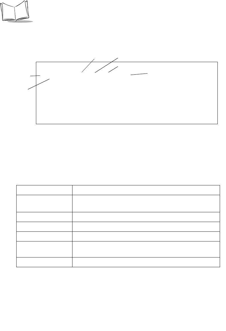
A-10
VRC 6940 Product Reference Guide
Field Diagnostic Test
During the Field Diagnostic Test the terminal displays and updates this screen:
Figure A-10. The Field Diagnostic Test
Tab l e A - 5 describes the field contents. The reports wrap so that the last five message reports
are visible. If you selected non-stop mode during setup, and the Ping Test or Error count fields
overflow, then the first detail line shows the most significant digits of the count, prefixed with
an asterisk.
Table A-5. Field Diagnostic Test Field Details
Field Description
Association Indicator A — the radio is associating with an AP.
U — the radio is not associating with an AP.
Ping Test Count Displays the number of each test as it runs.
Error Count Displays the cumulative number of errors that have occurred.
Retry Count The retry count for this message.
Timer The round-trip time in milliseconds, or an indication of error type,
if there was an error.
Access Point ID The ID of the AP with which the terminal is associating.
AP PING TEST
A Cnt Err Rty ms AP
56 0 0 165 18
57 0 0 55 18
58 1 1 TMO 18
59 1 0 220 18
60 1 0 58 18
Press ‘Q’ to Quit
Ping Test
Association
Error Count
Access Point ID
Indicator
Count
Retry Count
Timer

A-11
Utilities and Diagnostic Tests
When the test stops, the terminal displays a summary screen:
Figure A-11. The Field Diagnostic Test Results Screen
The summary shows:
!the elapsed time of the test
!total pings transmitted
!packet size used
!retry count
!number of timeouts
To repeat the test with the same parameters, press R. Press Q or CLEAR to end the test and
return to the DIAG24 menu.
FIELD DIAGNOSTICS
Total secs = 8.2
RF Secs = 4.9
Pings = 100
Packet size = 100
Timeouts = 4
[R]epeat or [Q]uit

A-12
VRC 6940 Product Reference Guide
CFG24 Configurator Utility
The CFG24 Spectrum24 Configurator utility lets you:
!configure radio communication parameters
!initialize a configuration stored in the NET.CFG file in the terminal’s current
directory
CFG24 updates NET.CFG settings every time it runs. It saves parameter settings to the radio
flash storage initialization area, and then checks for an association between the terminal and
an Access Point (AP).
Note: The Spectrum24 DOS ODI driver must be installed before you use
CFG24.
Starting the Utility
There are two ways to start the utility:
1. The first time you power up a VRC 6940 terminal the terminal loads essential
utilities and system drivers and displays the CFG24 Configurator utility as shown in
Figure A-12.
2. Alternate method: go to a DOS prompt and type: CFG24 [-I]. How you get to a
DOS prompt depends on what applications have been loaded onto the terminal, and
how they have been programmed. The DOS prompt may also appear if you boot the
terminal and it cannot connect to the network.
The optional parameter [-I] initializes the current configuration. If you are
configuring the terminal for the first time, this option starts the utility and displays
the Configurator menu.
Initializing the Radio
When you use the [-I] parameter, the utility initializes the radio using the settings currently
stored in NET.CFG. Default settings:
NET_ID: 101
Terminal IP address: 10.x.y.z (x, y, and z are the last 3 bytes of the IEEE address)
Subnet mask: 255.0.0.0
Default router: 0.0.0.0
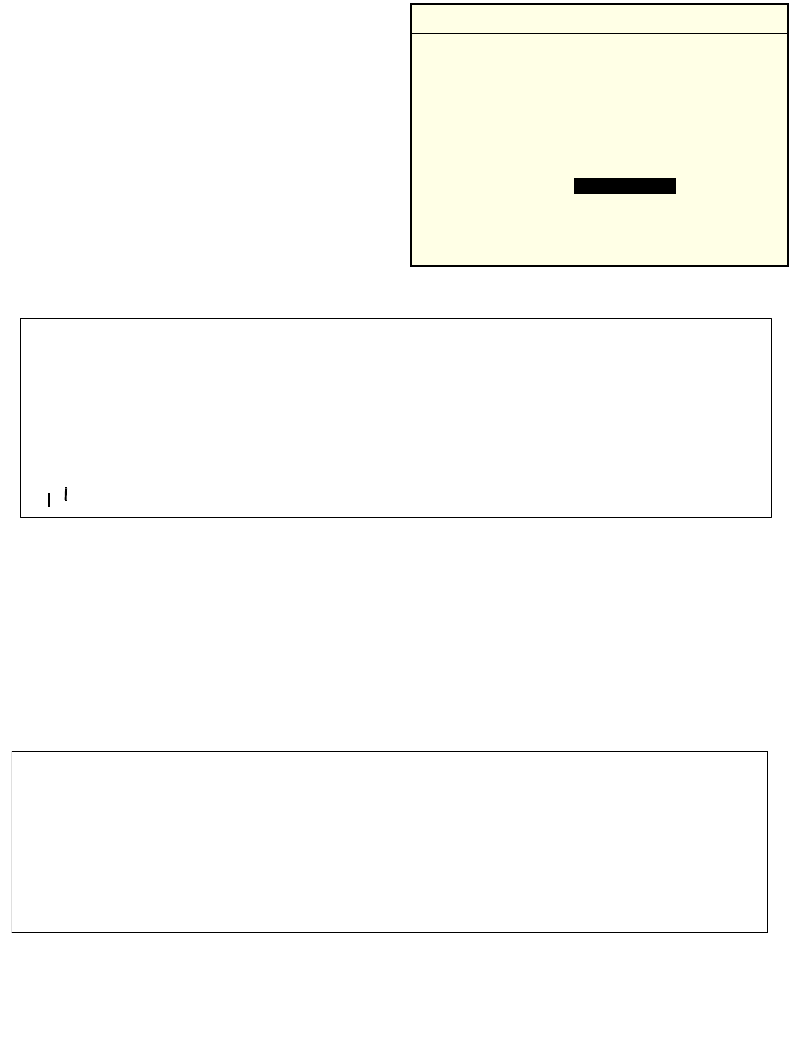
A-13
Utilities and Diagnostic Tests
The Configurator Menu
The Configurator menu appears the first time
you start the terminal, or if you launch the
CFG24 program without parameters. Figure
A-12 shows Configurator menu options.
Note that some terminals do not allow you to
change the Subnet Mask, Default Router
, and
Terminal IP addresses.
If you are using Spectrum24 802.11 protocol-
based software, the menu shows the ESS ID
option. For Spectrum24 Spring protocol-
based software, the menu shows Net ID.
Figure A-12. The CFG24 Configurator Menu
View Config Parameters
The View config option shows the terminal’s IEEE address, IP address, firmware version
number, and ESS ID or Net ID. To display the existing configuration parameters:
1. Select View config. Figure A-13 shows an example of the screen that appears.
2. Press CLEAR or ENTER to return to the Configurator menu.
Figure A-13. Viewing Configuration Parameters
reverse video
Configuration Note: Navigating the Menus
To navigate through the menus:
•Press UP or DOWN arrow keys to scroll
through menu options.
•To select, highlight the menu option you
want, then press ENTER. A highlighted op-
tion shows up in reverse video .
•To erase part of an entry, press BACK.
•To return to a previous menu press CLEAR.
•To exit to a DOS prompt, return to the Con-
figurator menu and press CLEAR.
reverse video
CONFIGURATOR X.XX
View config
ESS Id
Subnet Mask
Default Router
MU IP Address
Diversity
CLR, Enter
^
^
VIEW CONFIG
Terminal IEEE addr
00:A0:F8:28:78:EF
MU IP Address
0.0.0.0
FW: V3.29 981116
Net ID=101
CLR, Enter

A-14
VRC 6940 Product Reference Guide
ESS ID or Net ID
An ESS or Net ID identifies a radio network and differentiates between radio networks. All
equipment on one network must use the same ESS or Net ID. Spectrum24 terminals can
support the Spectrum24 802.11 or Spectrum24 Spring protocols. The menu displays the
ESS ID or Net ID, depending on which protocol you are using.
Terminals using Spectrum24 with the 802.11 protocol require an ES SID. The ES SID is a a
32-character alphanumeric value. Terminals using Spectrum24 with the Spring proprietary
network protocol require a Ne tID. The Ne tID is a three-character hexadecimal value.
To configure a terminal’s ESS ID or NET ID:
1. Select ESS ID or Net ID. Figure A-14 shows the entry for a Spring-based terminal.
2. Erase all or part of the entry, and type a new value from 100 to 1FE.
3. Press CLEAR or ENTER to return to the Configurator menu.
Figure A-14. Setting a NET ID
Subnet Mask
To configure the Subnet Mask:
1. Select Subnet Mask to display the screen shown in Figure A-15.
2. Erase all or part of the entry.
3. Type an IP address in decimal using the ddd.ddd.ddd.ddd format.
4. Press CLEAR or ENTER to return to the main menu.
NET ID
Enter Net Id:
150
BkSp, CLR, Enter

A-15
Utilities and Diagnostic Tests
Figure A-15. Setting a Subnet Mask
Default Router
The Default Router address is the node address that receives all packets destined for remote
networks. To configure the Default Router:
1. Select Default Router to display the screen shown in Figure A-16.
2. Erase all or part of the entry.
3. Type an IP address in decimal using the ddd.ddd.ddd.ddd format.
4. Press CLEAR or ENTER to return to the main menu.
Figure A-16. Setting a Default Router
SUBNET MASK
Enter SN Mask:
255.255.255.0
BkSp, CLR, Enter
DEFAULT ROUTER
Enter D Router:
0.0.0.0
BkSp, CLR, Enter

A-16
VRC 6940 Product Reference Guide
Terminal IP Address
If a boot server is not allocating IP addresses, you can set a Terminal IP Address:
1. Select MU IP Address to display the screen shown in Figure A-17.
2. Erase all or part of the entry.
3. Type an IP address in decimal using the ddd.ddd.ddd.ddd format.
4. Press CLEAR or ENTER to return to the main menu.
Figure A-17. Setting a Terminal IP Address
Diversity
To configure Diversity:
1. Select Diversity to display the screen shown in Figure A-18.
2. Use the UP or DOWN arrows to select an option. Always set Diversity set to No on
VRC 6940 terminals with only one antenna.
3. Press CLEAR or ENTER to return to the main menu.
Figure A-18. Configuring Diversity
MU IP ADDRESS
Enter IP address:
0.0.0.0
BkSp, CLR, Enter
DIVERSITY
2 antennas (Y/N)
No
BkSp, CLR, Enter

A-17
Utilities and Diagnostic Tests
MU Sleep Mode
If you set MU Sleep Mode On, the radio stays powered on when the rest of the terminal
powers down because of inactivity. You can wake the terminal by sending a message directly
to it, but broadcast messages will not wake it. If you set the switch Off, the radio powers off
if the rest of the terminal powers down because of inactivity. The default setting is On. To
configure MU Sleep Mode:
1. Select MU Sleep Mode to display the screen shown in Figure A-19.
2. Use the UP or DOWN arrow keys to select On or Off.
3. Press CLEAR or ENTER to return to the main menu.
Figure A-19. Setting Sleep Mode
Boot Mode
This option determines what network communication parameters the terminal will use when
it boots. To configure Boot Mode:
1. Select Boot Mode to display the screen shown in Figure A-20.
2. Use the UP or DOWN arrow keys to select Boot, DHCP
, or Manual Entry options.
3. Press CLEAR or ENTER to return to the main menu.
Figure A-20. Setting Boot Mode
MU SLEEP MODE
Radio State:
On
BkSp, CLR, Enter
BOOT MODE
Get IP from:
Manual Entry
BkSp, CLR, Enter

A-18
VRC 6940 Product Reference Guide
Boot Mode Options:
Power Management
If power management is set to PSP (the default), the radio only powers up if there is traffic
on the network. Because the radio is not always in a ready state when a message is sent to it,
PSP mode slows response times. If power management is set to CAM, the radio is always
ready to receive. To configure Power Management:
1. Select Pwr Management to display the screen shown in Figure A-21.
2. Use the UP or DOWN arrow keys to select PSP or CAM, then press ENTER.
3. Press CLEAR or ENTER to return to the main menu.
Figure A-21. Configuring Power Management
Boot Broadcasts a TCP/IP BOOTP request to the network. If they
have been configured to do so, boot servers on the network
send a response. The terminal accepts the first valid response it
receives, which contains a terminal IP address and other
network parameters that override any parameters entered
through CFG24.
DHCP Uses the same process as the Boot option but uses the Dynamic
Host Configuration Protocol.
Manual
Entry
The terminal does not broadcast any configuration messages to
the network. It uses the current network parameter values
(saved in the radio flash) to connect to the network.
PWER MANAGEMENT
Radio Pwr Mode:
PSP
BkSp, CLR, Enter

A-19
Utilities and Diagnostic Tests
Buffers
To configure the terminal Buffers:
1. Select Buffers to display the screen shown in Figure A-22.
2. Use the UP or DOWN arrow keys to select 4, 8,or 12, then press ENTER.
3. Press CLEAR or ENTER to return to the main menu.
Figure A-22. Configuring the Buffers
Re-Transmit Delay
To configure the Re-Transmit Delay:
1. Select ReXmit Delay to display the screen shown in Figure A-23.
2. Use the UP or DOWN arrow keys to select short or long, then press ENTER.
3. Press CLEAR or ENTER to return to the main menu.
Figure A-23. Setting the Re-Transmit Delay
BUFFERS
Enter Buf Cnt:
8
BkSp, CLR, Enter
REXMIT DELAY
Enter Delay:
short
BkSp, CLR, Enter

A-20
VRC 6940 Product Reference Guide
Rate Control
To configure the Rate Control:
1. Select Rate Control to display the screen shown in Figure A-24.
2. Use the UP or DOWN arrow keys to select 1Mb only, 2Mb only, or 1Mb and 2 Mb
options, then press ENTER. For Spring protocol, 1Mb is the only choice.
Figure A-24. Setting the Rate Control
Scanner/RF Operation
To configure the Scanner/RF operation:
1. Select Scan/RF Op to display the screen shown in Figure A-24.
2. Use the UP or DOWN arrow keys to select Concurrent Op or Scan stops RF. Then
press ENTER.
If you want an attached scanner and the radio to both operate at the same time, select
Concurrent Op. If you want radio operation to be suspended during a scan, select
Scan stops RF.
Figure A-25. Setting Scanner/RF Operation
RATE CONTROL
TX Rate:
1 MB only
BkSp, CLR, Enter
SCAN/RF OP
Select Op Mode:
Concurrent Op
BkSp, CLR, Enter

A-21
Utilities and Diagnostic Tests
Flash Utility
The flash.bat utility lets you copy, delete or rename files on the flash disk: it switches the
flash disk to write mode, performs the operation, and then returns the flash disk to read-only
mode. The LWP software copies flash.bat onto the E:\ drive the first time you start the
terminal.
Deleting
To delete a named file from the current directory of the flash disk:
flash del filename.ext
To delete all the files in the root directory of the flash disk:
flash del \*.*
Important! You don’t have to name the E: drive to erase all of the root directory files.
Copying
To copy the protocol stack configuration file (net.cfg) from the current directory to the root
directory on the flash disk:
flash copy net.cfg \
To copy a file (filename.ext) from the SVTP directory on the flash disk to the STEP
directory on the flash disk:
flash copy e:\svtp\filename.ext \step
Note: If you are copying from the E:\ drive, specify it on the first command parameter, but
do NOT specify it on the second parameter, where it is assumed. You can only use this option
to copy to the flash drive.
Renaming
To rename netcfg.1 in the flash disk root directory to net.cfg:
flash ren \netcfg.1 net.cfg
Normal restrictions for a DOS file re-name apply, i.e., netcfg.1 must exist and net.cfg
must not exist in the directory before the command is executed.

A-22
VRC 6940 Product Reference Guide

B-1
Appendix B Software Environment
This section describes the software environment for a VRC 6940 terminal. A VRC 6940 has
four drives as described in Tab le B-1:
Table B-1. VRC 6940 Drives
Drive Size Type Contents
A:\ 256 Kb Flash,
EPROM
This drive contains:
• BIOS, including the Command Mode menus and
commands and Self-Test software
• Essential system drivers
• DOS
B:\ 256 Kb Flash,
EEPROM
This drive is the main space for user applications. For
the first installation, it contains the LWP hex image.
The first time you boot a terminal, LWP copies utilities
and applications onto the E:\ drive. When you load
user applications onto the terminal, they overwrite
LWP, but the utilities and applications stay on the E:\
drive.
See Chapter 4 for information on loading applications
into this space.
D:\ 160 Kb RAM This drive contains the net.cfg file and user space.
Commands in the b:\autoexec.bat file can write
files to this disk.
The default size is 160 Kb, but this size can be changed
by b:\init.exe. For information on setting the D
drive size, see Chapter 5 of the Series 3000 Application
Programmer’s Guide (p/n 70-16308-XX).

B-2
VRC 6940 Product Reference Guide
Boot Sequence
The first time a new terminal powers up:
1. A:\config.sys loads drivers.
2. A:\autoexec.bat calls and runs B:\autoexec.bat.
3. B:\autoexec.bat loads the application files contained in the LWP.HEX file by
decompressing them into an application subdirectory on E:\ (see LAN WorkPlace
(LWP) Software on page B-3).
4. A second batch file displays a menu with terminal configuration options.
5. A third batch file loads the protocol stack to enable application-to-host connections.
If the terminal boots and the Spectrum24 radio card has no parameters, the terminal runs the
CFG24 software so that you can configure the radio card. Chapter 3 describes how to
configure the radio card.
If the Spectrum24 radio card has parameters, the terminal tries to connect to an AP. If it can
connect, the terminal starts a session and continues to boot normally. If it can’t find an AP,
the screen displays a NOT ASSOCIATED message, and a DOS prompt appears. At this point
you can run the DIAG24 ping utility (see page 6-5).
After you have started the terminal, and LWP.HEX has installed the utility files into their
appropriate directories, you can install end-user applications onto the terminal. When you
transfer a new HEX image onto the terminal, it overwrites the LWP.HEX image. The Program
Loader then installs the new HEX image by converting the ASCII data stream into files to be
stored in non-volatile flash memory on the B:\ drive.
E: 1MB Flash This drive is normally read-only, although it can be
controlled by application programming on drive B.
The LWP hex image copies these utilities into this
space:
• BOOTP
• CFG24
• DIAG24
• FLASH.BAT
Table B-1. VRC 6940 Drives
Drive Size Type Contents

B-3
Software Environment
LAN WorkPlace (LWP) Software
All VRC 6940 terminals have a copy of LWP.HEX loaded at the factory. The first time you
start the terminal, it installs the utilities listed below onto the E:\drive.
Software Files
Tab l e B-2 shows the contents of each drive after the LWP hex image is loaded on E:\ drive:
CFG24 The CFG24 Configurator utility that allows you to configure the
Spectrum24 radio. You can run it from a DOS prompt. See page A-12 for
more information.
DIAG24 The DIAG24 Diagnostics utility that allows you to run Access Point ping
tests. You can run it from a DOS prompt. See page A-5 for more
information.
BOOTP BOOTP boot utility. It requests and receives an IP address and then sets
up communications parameters for use by other parts of the system. It
executes automatically during start-up procedures. Do not run it from a
DOS prompt. See page A-17 for more information on configuring boot
mode.
FLASH A batch file that provides some flash disk housekeeping functions. You
can run it from a DOS prompt. See page A-21 for more information.
Table B-2. VRC 6940: Software Files
Directory File Name Description
A:\ LOADER.EXE An NVM loader utility that can be used in place of the
Command Mode Program Loader. For more
information, see the Series 3000 Application
Programmer’s Reference Manual (p/n 70-16309-XX).
SHELL.COM The DOS command shell.
AUTOEXEC.BAT Calls B:\autoexec.bat, if it exists, and executes it.
If there is no B:\ drive, the terminal boots into
Command Mode.
DSKBCHK.COM Checks to see if the terminal has been configured with
a B:\ drive. For more information, see the Series 3000
Application Programmer’s Reference Manual (p/n 70-
16309-XX).

B-4
VRC 6940 Product Reference Guide
A:\
(cont’d)
2WAY3000.SYS A Series 3000 Protocol Device Driver. For more
information, see the Series 3000 System Software
Manual (p/n 70-16310-XX).
S1.BIN A Spectrum One radio driver.
CONFIG.SYS A configuration file that loads essential drivers and
files. It loads A:\shell.com
B:\ COMMAND.COM A command batch file.
AUTOEXEC.BAT Loads the application files contained in the LWP.HEX
file by decompressing them into an application
subdirectory on E:\ drive.
ERR3000.SYS An error message driver.
PKUNZJR.COM An unzip utility.
FLASHDSK.SYS The flash disk driver.
FLSHCTL.EXE Switches the flash disk between read-write and read-
only modes.
FLSHFMT.EXE A utility used to format the flash disk.
D:\ NET.CFG The Spectrum24 configuration file. This file is
configured by the CFG24 Configurator utility.
_AP.BAT Built by FLSHAUTO.BAT for use in the warm boot
process.
E:\ NET.CFG Configuration file used by LSL.COM,
SLAODI3K.COM, and TCPIP.EXE to get
configuration parameters.
FLSHAUTO.BAT Initialization batch file. Loads the radio driver and the
TCP/IP stack.
FLSHAUT1.BAT Builds the _AP.bat file for use.
MSG.MSG File used by the DIAG24 Ping utility.
Table B-2. VRC 6940: Software Files
Directory File Name Description

B-5
Software Environment
E:\
(cont’d)
APPINIT.COM Scans the flash disk for valid applications. If it finds
more than one, it displays an application selection
menu. A valid RF application has a home directory in
the flash disk’s root directory containing a file called
RUN.BAT. This is how the system knows which
applications are present, and which are batch
applications.
CBT.COM Utility to re-initialize (cold boot) the terminal.
WBT.COM Utility to re-initialize (warm boot) the application.
WAIT.EXE A command used in batch files to pause the display
for a specified number of seconds. The pause can be
interrupted with the CTRL-FUNC-1 key sequence. If
interrupted, the command returns an errorlevel 1.
GETSTR.EXE Prompts for keyboard input, which is placed as a
character string in the environment variable _STR.
Used to customize utility files for building an
application HEX during developer kit installation.
LSL.COM Novell’s Netware Link Support Layer software. Used
to access the physical network, in this case a PCMCIA
radio card.
DIAG24.EXE A diagnostic ping utility for diagnosing possible radio
problems. See page A-5 for more information.
CFG24.EXE A utility for configuring Spectrum24 radio
parameters. See page A-12 for more information.
BOOTP A utility that requests and receives an IP address and
sets up communications parameters for use by other
parts of the system. It runs automatically during start-
up. Do not run it from a DOS prompt.
TCPIP.EXE Novell’s Lan Workplace stack version 5.0.
PIPCT.EXE Used to save and restore part of the BIOS work area
overwritten when TCPIP.EXE is loaded.
SS.BAT Batch file to run DIAG24 for site survey purposes.
Table B-2. VRC 6940: Software Files
Directory File Name Description

B-6
VRC 6940 Product Reference Guide
E:\
(cont’d)
TDREM.EXE Remote end of serial link used to transfer files to and
from a terminal. Used mainly during development but
also a useful diagnostic tool.
FLASH.BAT A flash utility for copying, renaming or deleting files
from flash memory. Useful in development for
transferring single files to flash disk. See page A-21 for
more information.
RAMINIT.EXE Copies _AP.BAT to new RAM disk. The _AP.BAT is
saved by a previous RAMCHG. The _AP.BAT must
be smaller than 120 bytes.
RAMCHG.EXE Changes the RAM disk size and warm boots the
terminal. RAMCHGnn changes the RAM disk to
nnKBytes.
RF_VER.COM Radio utility file.
RFOFF.COM Used for batch application to unconditionally turn off
the radio adapter to conserve battery life.
UPD802
(sub-directory)
Stores files to update radio to become 802.11
compatible.
TFTPC.COM Encapsulation for TFTP.EXE to allow trapping of
error messages. This allows the re-trying of a file
transfer if an error is found.
TFTP.EXE Trivial File Transfer Protocol software.
TFTP.MSG TFTP message file.
LWP.MSG TCP/IP message file.
BGET.BAT Batch file for doing TFTP file transfers from a server
to the flash disk. If the file already exists on the
current directory on the flash disk (normally the
current application’s home directory), the file is not
transferred. BGET.BAT calls FGET.BAT to perform the
actual transfer.
Table B-2. VRC 6940: Software Files
Directory File Name Description

B-7
Software Environment
E:\
(cont’d)
FGET.BAT Batch file for doing TFTP file transfers from a server
to the flash disk. If the transfer fails it is retried. The
server IP address is picked up from the environment
variable SIADDR, which is set up by BOOTP.COM if
either a BOOTP or DHCP process is performed.
UPDATE.BAT Batch file used for an over-the-air software update
facility. It downloads a ZIP file and unzips it into the
application directory. The ZIP file is the same file that
was placed in the application HEX.
CHK_ID.EXE Checks to see if the ident.txt files on the paths
specified in the command-line are identical. Used in
apphex.bat to check for the need to copy the
application files to the flash disk.
GETNUM.EXE Returns an errorlevel depending on a single key hit.
Returns errorlevel n if the numeric key ‘n’ is pressed.
All other keys return errorlevel 99. Used to make
menu selections in batch files.
IDENT.TXT Used to identify a particular HEX build.
SLAODI3K.COM Wireless LAN adapter driver.
APP
(sub-directory)
Applications stored in this directory.
Table B-2. VRC 6940: Software Files
Directory File Name Description

B-8
VRC 6940 Product Reference Guide

C-1
Appendix C Keyboard Layouts
This section describes the characters and character sequences produced by the 54-key
keyboard using the default translation tables. Ta bl e C-1 displays the information in table
format. Figures C-1 to C-10 show keyboard illustrations.
These key definitions can be changed by application programs. Refer to the Series 3000
Application Programmer's Reference Manual (p/n 70-16309-XX) and the Series 3000 System
Software Manual (p/n 70-16310-XX) for additional information on keyboard translation.
Table C-1. VRC 6940 Key Combinations
Unmodified Shift Caplock Ctrl Func Shift+Func Func+Ctrl Ctrl+Func Alt+Func
Enter Enter Enter Line feed = + none none none
Clear Clear Clear Clear Clear Clear none Clear none
Ctrl Ctrl Ctrl none Alt Alt none Alt none
Shift Shift Shift none none none none Shift none
Func Func Func none none none Func none none
Pwr Pwr Pwr Pwr Pwr Pwr Pwr Pwr Pwr
aA A Ctrl, A a A Alt, A none none
bB B Ctrl, B b B Alt, B Ctrl, B Alt, B
cC C Ctrl, C c C Alt, C Ctrl, C Alt, C
dD D Ctrl, D d D Alt, D Ctrl, D Alt, D
eE E Ctrl, E e E Alt, E Ctrl, E Alt, E
fF F Ctrl, F f F Alt, F Ctrl, F Alt, F
gG G Ctrl, G g G Alt, G Ctrl, G Alt, G

C-2
VRC 6940 Product Reference Guide
hH H Ctrl, H F1 Shift, F1 Alt, H Ctrl, F1 Alt, F1
iI I Ctrl, I Dark Dark Alt, I Dark Dark
jJ J Ctrl, J Light Light Alt, J Light Light
kKKCtrl, KBckLt
1BckLt1Alt, K BckLt1BckLt1
lL L Ctrl, L Caplock Caplock Alt, L Caplock Caplock
mM M Ctrl, M F9 Shift, F9 Alt, M Ctrl, F9 Alt, F9
nN N Ctrl, N Numlock Numlock Alt, N none Numlock
oO O Ctrl, O o O Alt, O Ctrl, O Alt, O
pP P Ctrl, P p P Alt, P Ctrl, P Alt, P
qQ Q Ctrl, Q q Q Alt, Q Ctrl, Q Alt, Q
rR R Ctrl, R r R Alt, R Ctrl, R Alt, R
sS S Ctrl, S F10 Shift, F10 Alt, S Ctrl, F10 Alt, F10
tT T Ctrl, T t T Alt, T Ctrl, T Alt, T
uU U Ctrl, U + + Alt, U none none
vV V Ctrl, V - - Alt, V none none
wW W Ctrl, W * none Alt, W Ctrl, * none
xX X Ctrl, X / ? Alt, X none none
yY Y Ctrl, Y y Y Alt, Y Ctrl, Y Alt, Y
zZ Z Ctrl, Z z Z Alt, Z Ctrl, Z Alt, Z
Back Backspace Backspace Ctrl, Break Space Space none Space none
Left Arrow 4 Left Arrow Ctrl, Left
Arrow
Home 7 none Ctrl, Home none
Right Arrow 6Right
Arrow
Ctrl, Right
Arrow
End 1 none Ctrl, End none
Up Arrow 8 Up Arrow Ctrl, Up
Arrow
Page Up 9 none Ctrl, Page
Up
none
Dwn Arrow 2 Dwn Arrow Ctrl, Dwn
Arrow
Page Down 3 none Ctrl, Page
Down
none
0) 0 none Ins 0 Alt, 0 none none
1 Functional only on units equipped with the keyboard backlight option.
Table C-1. VRC 6940 Key Combinations
Unmodified Shift Caplock Ctrl Func Shift+Func Func+Ctrl Ctrl+Func Alt+Func

C-3
Keyboard Layouts
1! 1 none ’“ Alt, 1 none none
2@ 2 Ctrl, 2 , < Alt, 2 none none
3# 3 none / ? Alt, 3 none none
4$ 4 none [ { Alt, 4 Ctrl, 4 none
5% 5 none ] } Alt, 5 Ctrl, 5 none
6^ 6 Ctrl, 6 ; : Alt, 6 none none
7& 7 none ‘~ Alt, 7 none none
8* 8 none = + Alt, 8 none Alt, =
9( 9 none \ | Alt, 9 Ctrl, \ none
-_ - Ctrl, - - _ Alt, - Ctrl, - Alt, -
.> . none Del . none none none
F1 Shift, F1 F1 Ctrl, F1 F6 Shift, F6 Alt, F1 Ctrl, F6 Alt, F6
F2 Shift, F2 F2 Ctrl, F2 F7 Shift, F7 Alt, F2 Ctrl, F7 Alt, F7
F3 Shift, F3 F3 Ctrl, 3 F8 Shift, F8 Alt, F3 Ctrl, F8 Alt, F8
F4 Shift, F4 F4 Ctrl, F4 F9 Shift, F9 Alt, F4 Ctrl, F9 Alt, F9
F5 Shift, F5 F5 Ctrl, F5 F10 Shift, F10 Alt, F5 Ctrl, F10 Alt, F10
Table C-1. VRC 6940 Key Combinations
Unmodified Shift Caplock Ctrl Func Shift+Func Func+Ctrl Ctrl+Func Alt+Func
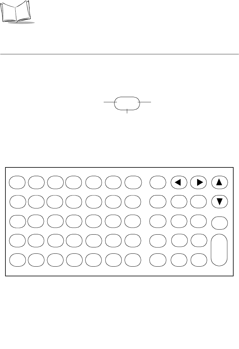
C-4
VRC 6940 Product Reference Guide
Keyboard Character & Character Combination
Illustrations
The captions indicate what sequence of modifier keys produce the keyboard character.
FUNC and SHIFT-FUNC key combinations (Figure C-5 and Figure C-9) produce scan codes,
ASCII values, and printable characters/logical key sequence names. The keys are illustrated
as follows:
Figure C-1. Key Captions
Figure C-2. Unshifted Keyboard
SS AA
C
Scan Code
(decimal) ASCII Value
(decimal)
Printable Character or Logical Key
Sequence Name
n
F1 F2 F3 F4 F5
ON/OFF
BACK CTRL
ab cd eg
f789
hi jklm456
op qr sut 123
CLEAR
vwxy
zFUNC
SHIFT _0.
ENTER
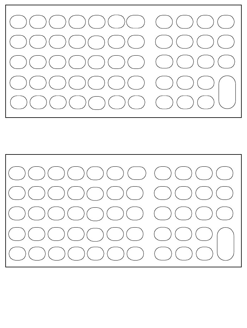
C-5
Keyboard Layouts
Figure C-3. Shift-Modified Keyboard
Figure C-4. Ctrl-Modified Keyboard
Shift
F1 CTRL
ABC DE G
F&* (
HI J KLN
M$%^
OPQ RSU
T!@#
CLEAR
VWX YZ _)>
ENTER
Shift
F2 Shift
F3 Shift
F4 BACK
Shift
F5 468
2
ON/OFF
Ctrl
F1 Ctrl
F2 Ctrl
F3 Ctrl
F4 Ctrl
F5 Ctrl
Brk CTRL
Ctrl
A
Ctrl
HCtrl
ICtrl
JCtrl
KCtrl
LCtrl
NCtrl
6
Ctrl
O
Ctrl
PCtrl
QCtrl
RCtrl
S
Ctrl
U
Ctrl
TCtrl
2
CLEAR
Ctrl
VCtrl
WCtrl
XCtrl
ZCtrl -
Line
Feed
Ctrl ↑
↑↑
↑
Ctrl →
→→
→
Ctrl ↓
↓↓
↓
Ctrl
BCtrl
CCtrl
DCtrl
F
Ctrl
ECtrl
G
Ctrl
M
Ctrl
Y
Ctrl ←
←←
←
ON/OFF
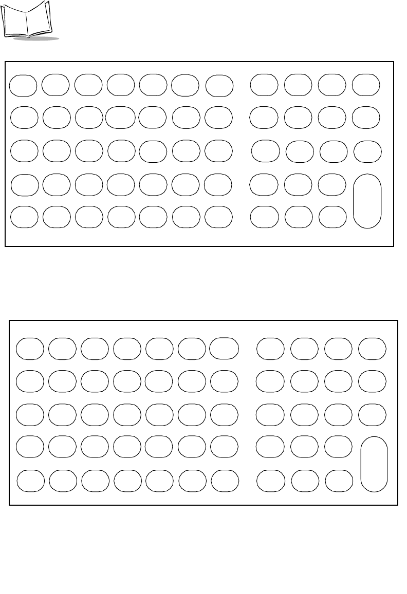
C-6
VRC 6940 Product Reference Guide
Figure C-5. Func-Modified Keyboard
Figure C-6. Alt-Modified Keyboard
81 00
PgDn
41 96
‘
13 61
=43 92
\
CLEAR
64 00
F6
65 00
F7
66 00
F8
67 00
F9
68 00
F10
57 32 73 00
PgUp
29 00
Alt 71 00
Home 79 00
End
56 00
a
48 98
b
29 00
c
32 100
d
18 101
e
33 102
f
34 103
g
59 00
F1
101
Dark
102
Light
100
BckLt*
58 00
CapLk
67 00
F9
69 00
NumLk
24 111
o25 112
p16 113
q
19 114
r68 00
F10
20 16
t78 43
+
74 45
-
55 42
*
53 47
/
21 121
y44 122
z
26 91
[
27 93
]39 59
;
40 39
’
51 44
,
53 47
/13 61
=
12 45
-
82 00
Ins 83 00
Del
01 27
Space
* Functions only on units equipped with the keyboard backlight option.
ON/OFF
Alt
F1
Alt 8
Alt 4 Alt 6
Alt 1 Alt 2 Alt 3
Alt - Alt 0
Alt
F2 Alt
F3 Alt
F4 Alt
F5
Alt A Alt B Alt C Alt D Alt E Alt F Alt G
Alt H Alt I Alt J Alt K Alt L Alt M Alt N
Alt O Alt P Alt Q Alt R Alt S Alt T Alt U
Alt V Alt W Alt X Alt Y Alt Z
Alt 7 Alt 9
Alt 5
ON/OFF
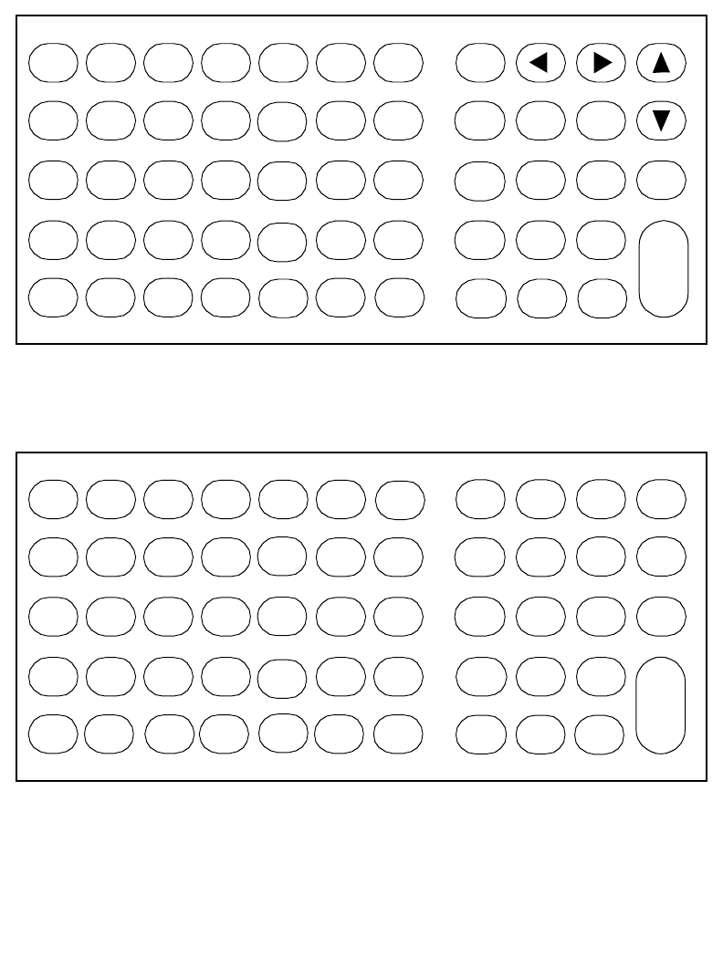
C-7
Keyboard Layouts
Figure C-7. Caplock-Modified Keyboard
Figure C-8. Ctrl + Func-Modified Keyboard
F1 F2 F3 F4 F5
ON/OFFBACK
CTRL
ABC DEG
F789
HI J KL N
M 4 56
OPQ RS U
T12 3
CLEAR
VWX YZ FUNC _0.
ENTER
Ctrl
F6 Ctrl
F7 Ctrl
F8 Ctrl
F9 Ctrl
F10 BACK Alt
Ctrl
BCtrl
D
Dark CapLk
Ctrl
P
CLEAR
SHIFT Ctrl -
ENTER
Ctrl
Home Ctrl
End Ctrl
Pgup
Ctrl
ECtrl
FCtrl
G
Ctrl
F1 Light BckLt* Ctrl
F9
Ctrl
OCtrl
QCtrl
RCtrl
F10 Ctrl
T
Ctrl
*Ctrl
YCtrl
Z
Ctrl \
Ctrl
4Ctrl
5
Ctrl
Pgdn
* Functions only on units equipped with the keyboard backlight option.
ON/OFF
C-8
VRC 6940 Product Reference Guide
Figure C-9. Shift+ Func-Modified Keyboard
Figure C-10. ALT + Func-Modified Keyboard
ON/OFF
CLEAR
89 00
Shft F6 90 00
Shft F7 91 00
Shft F8 92 00
Shft F9 93 00
Shft F10
57 32
Space
56 00
A
48 66
B
29 00
C
32 68
D
18 69
E
33 70
F34 71
G
84 00
Shft F1
101
Dark
101
Light
100
BckLt*
58 00
CapLk
92 00
Shft F9
69 00
NumLk
24 79
O
25 80
P
16 81
Q
19 82
R
93 00
Shft F10
20 84
T
78 43
+
74 45
-53 63
?
21 89
Y
44 90
Z
29 00
Alt 71 55
7
73 57
9
79 49
1
81 51
3
41 126
~
13 43
+
43 124
|
26 123
{
27 125
}
39 58
:
40 34
“
51 60
<
53 63
?
12 95
_82 48
0
83 46
.
13 43
+
01 27
* Functions only on units equipped with the keyboard backlight option.
Alt
F6 ON/OFF
Dark
Alt
F7 Alt
F8 Alt
F9 Alt
F10
Alt
CAlt
DAlt
EAlt
FAlt
G
Alt
F1 Light BckLt* CapLk Alt
F9 NumLk
Alt
OAlt
PAlt
QAlt
RAlt
F10 Alt
T
Alt
YAlt
Z
Alt
=
Alt
-
Alt
B
* Functions only on units equipped with the keyboard backlight option.

D-1
Appendix D Environmental and Technical
Specifications
This appendix describes:
!physical, environmental, and operational information for VRC 6940 terminals
!reference information for the COM1 and scanner ports
!mappings for the null modem pinouts
Specifications
Tab l e D -1 summarizes physical, operational, and environmental specifications for the VRC
6940.
Table D-1. VRC 6940 Specifications
Dimensions 12” x 9” x 3" / 310 mm x 234 mm x 81 mm
(LxWxD)
Weight 6.7 lbs
Data Communication RS-232 serial port
Power Requirements 9 - 60 VDC
Backup Battery NiMH
Display Size 8 line x 40 character
Display Vacuum Fluorescent
Number of Keys 54 keys
Radio Module Internal PCMCIA

D-2
VRC 6940 Product Reference Guide
Scanner Port
The Scanner Port is located on the back panel of the VRC 6940. Table D-2 lists the pin
descriptions.
Microprocessor NEC V25
Housing Magnesium Alloy
Sealing IP65 and NEMA4
Vibration Specification SAE 1445
Operating Temperature:
without internal heater
with optional internal heater
-2°F to 122° F / -20°C to 50° C
-22°F to 122°F / -30°C to 50°C
Storage Temperature -40°F to 140° F/ -40°C to 60° C
RF Technology: 2.4 GHz Yes
Operating System DR-DOS
Architecture 16 Bit
Memory:
RAM
FLASH
640KB
1.2MB
Programming Tool 16 Bit Application Developer's Toolkit
Table D-2. Scanner Port Pin Descriptions
Pin Name Function Direction
1 SOS Start of scan1input
2 BARDATA Bar code data input
3 LEDEN L.E.D. enable output
4 LASERTRIGN Laser trigger not input
5 LASEREN Laser enable output
6 GROUND Logic/power ground N/A
7 LASERVCC Laser power (+5V) output
1Must be grounded on contact–wand scanners
Table D-1. VRC 6940 Specifications

D-3
Environmental and Technical Specifications
COM1 Serial Port
The COM1 Serial Port is located on the back panel of the VRC 6940. Table D-3 lists the pin
descriptions.
Table D-3. COM1 Serial Port Descriptions
Pin Name Signal Direction
1 GROUND GND IN1
2 TRANSMIT DATA TXD OUT1
3 RECEIVED DATA RXD IN1
4 REQUEST TO SEND RTS OUT1
5 CLEAR TO SEND CTS IN1
6 DATA SET READY DSR IN1
7 SIGNAL GROUND GND —1
8 CARRIER DETECT DCD IN1
9 Not used
10 Not used
11 REV CH OUT1
12-19 Not used
20 DATA TERMINAL READY DTR OUT1
21 Not used
22 RING INDICATOR RI IN1
23 Not used
24 Reserved2
25 Reserved2
1RS-232 signal
2Symbol internal test signals
D-4
VRC 6940 Product Reference Guide
Null Modem
A null modem cable is used for:
!downloading programs from a PC to a VRC 6940 terminal
!unloading memory contents from a VRC 6940 terminal to a PC
The cable has a 16-pin male circular connector, and a 25-pin female D-Connector. Tabl e D -
4 shows the pin-outs for both connectors.
Table D-4. Null Modem Pin Out Descriptions
VRC6940 16-Pin Circular Connector
(Male)
Host 25-Pin D-Connector
(Female)
Pin Name Pin Name
1DCD20DTR
2 RXD 2 TXD
3 TXD 3 RXD
4 DTR 6, 8 DSR, DCD
5 GND 7 GND
6DSR20DTR
7RTS5CTS
8CTS4RTS

E-1
Appendix E Communications Status Codes
Communications Status Codes
When the Program Loader and Memory Transfer utilities complete their functions, they
return communication status codes in the form of a four hexadecimal number. A status code
of 0000 indicates success; any other code indicates failure. Tabl e E-1 describes the conditions
associated with the status codes.
Table E-1. Communications Status Codes
Status Code Meaning
0002 Receive overrun error
0004 Receive parity error
0008 Receive framing error
0010 Programming voltage not present
0020 Data Set Ready or Carrier Detect not detected on open
0080 ABORT key hit during comm
0100 CD lost during session
0200 Illegal Intel hexadecimal record
0400 Either unsupported Intel record
0600 NVM EEPROM failed to erase
0800 Receive time-out error
1000 Control start character time-out
2000 Clear To Send inactive time-out error
4000 Receive buffer full

E-2
VRC 6940 Product Reference Guide

Glossary-1
Glossary
Access Point
A device that provides transparent access between Ethernet wired networks and IEEE 802.11
interoperable radio-equipped mobile units (MUs). Symbol’s hand-held computers, or other
devices equipped with a PCMCIA slot, communicate with wired networks using Access
Points (AP). The mobile unit may roam among the APs in the same subnet while maintaining
a continuous, seamless connection to the wired network. Refer to Subnet.
AP
See Access Point.
API
Application Programming Interface. An interface that gives one software component the
ability to communicate with or control another. Usually used to refer to services provided by
one software component to another when using software interrupts or function calls.
ASCII
American Standard Code for Information Interchange. A 7 bit code representing 128 letters,
numerals, punctuation marks, and control characters. It is a standard data transmission code
in the U.S.
Bar Code
A pattern of variable-width bars and spaces which represents numeric or alphanumeric data
in machine-readable form. The general format of a bar code symbol consists of a leading
margin, start character, data or message character, check character (if any), stop character,
and trailing margin. Within this framework, each recognizable symbology uses its own
unique format. See Symbology.

Glossary-2
VRC 6940 Product Reference Guide
Baud Rate
A measure for data transmission speed.
BIOS
Basic Input Output System. A collection of ROM-based code with a standard API used to
interface with standard PC hardware.
Bit
Binary digit. One bit is the basic unit of binary information. Generally, eight consecutive bits
compose one byte of data. The pattern of 0 and 1 values within the byte determines its
meaning.
Bits per Second (bps)
Number of bits transmitted or received per second.
BOOTP
Bootstrap protocol. A TCP/IP protocol that enables a VRC 6940, for example, to learn its IP
address from a centrally administered server. It does this by broadcasting a TCP/IP BOOTP
request message to the network. Boot servers on the network respond if configured to do so.
The terminal accepts and uses the first valid IP address that it receives and, optionally, other
network parameters.
Byte
On an addressable boundary, eight adjacent binary digits (0 and 1) combined in a pattern to
represent a specific character or numeric value. Bits are numbered from the right, 0 through
7, with bit 0 the low-order bit. One byte in memory can be used to store one ASCII character.
Data Communications Equipment (DCE)
A device such as a modem that is designed to attach directly to a DTE (Data Terminal
Equipment) device.
Data Terminal Equipment (DTE)
A device such as a terminal or printer that is designed to attach directly to a DCE (Data
Communications Equipment) device.
Decode
To recognize a bar code symbology (e.g., Codabar, Code 128, Code 3 of 9, UPC/EAN, etc.)
and analyze the content of the bar code scanned.

Glossary-3
Glossary
DOS
Disk Operating System. This is basic software that allows you to load and use software
applications on your computer. VRC 6940 terminals use a product called DR-DOS.
DR-DOS
Disk operating system software on VRC 6940 terminals. It is compatible with and extends
the industry-standard IBM PC-DOS, and provides access to a number of commercially
available programming tools.
EEPROM
Electrically Erasable Programmable Read-Only Memory. An on-board non-volatile memory
chip. See NVM.
ESS ID
Allows facilities using 802.11 protocol to limit which Access Points a VRC 6940 terminal can
communicate with. The terminal can only communicate with Spectrum24 Access Points that
have matching ESS IDs. See Spectrum24 documentation for further information.
File Transfer Protocol (FTP)
A TCP/IP application protocol governing file transfer via network. See TCP/IP.
Flash Disk
Non-volatile memory for storing application and configuration files.
Flow Control
The procedure for adjusting the flow of data from one device to another to ensure that the
receiving device can handle all of the incoming data.
FTP
See File Transfer Protocol.
HEX Image
A file format used for installing applications on the VRC 6940. The image may contain BIOS
information, applications, and instructions for transferring the applications.
Host
A computer that serves other terminals in a network, providing services such as network
control, database access, special programs, supervisory programs, or programming
languages.

Glossary-4
VRC 6940 Product Reference Guide
I/O Ports
Input/Output Ports. The I/O ports are primarily dedicated to passing information into or out
of the terminal’s memory. The VRC 6940 terminal includes a Serial port and a Scanner port.
IP Address
A 32-bit address assigned to nodes on a TCP/IP network. The address is written as four octets
separated by periods (dotted decimal format), e.g., 130.24.34.03. They represent a network
section, an optional subnet section, and a host section. Also see Terminal IP Address .
LAN
Local Area Network.
Liquid Crystal Display (LCD)
A display that uses liquid crystal sealed between two glass plates. The crystals are excited by
precise electrical charges, causing them to reflect light outside according to their bias. They
use little electricity and react relatively quickly. They require external light to reflect their
information to the user.
Light Emitting Diode (LED)
A low power electronic light source commonly used as an indicator light. It uses less power
than an incandescent light bulb but more than a Liquid Crystal Display (LCD).
MU
Mobile Unit.
Net ID
A Net ID allows facilities using Spring protocol to limit which Access Points a VRC 6940
terminal can communicate with. The terminal can only communicate with Spectrum24
Access Points that have matching Net IDs. See the Spectrum24 documentation for more
information.
NVM
Non-volatile memory. This is memory that retains its contents after its power supply is
removed or turned off. Files and programs contained in NVM help load programs onto the
terminal and provide an environment for running programs.
Null Modem
A special cable that allows direct connection between two DTE (Data Terminal Equipment)
devices by making each one emulate a DCE (Data Communications Equipment) device.
Glossary-5
Glossary
Parity
A technique for verifying whether or not data has been lost or overwritten when it is
transferred from one place in storage to another or between computers.
PCMCIA
Personal Computer Memory Card Interface Association.
PCMCIA Card
A plug-in expansion card for laptop computers and other devices, also called a PC Card. PC
Cards are 85.6 mm long x 54 mm wide, and have a 68 pin connector. There are several
different kinds:
RAM
Random Access Memory. Data in RAM can be accessed in random order, and quickly written
and read.
RF
Radio Frequency.
ROM
Read-Only Memory. Data stored in ROM cannot be changed or removed.
Router
A device that connects separate networks. Routers are typically used to extend the range of
cabling and to organize the topology of a network into subnets. They also support the
required protocols for packet filtering. Refer to Subnet.
RTC
Real Time Clock.
Type Height Common Use
Type I 3.3 mm RAM or Flash RAM
Type II 5 mm modems, LAN adaptors
Type III 10.5 mm Hard Disks

Glossary-6
VRC 6940 Product Reference Guide
Scanner
An electronic device used to scan bar code symbols and produce a digitized pattern that
corresponds to the bars and spaces of the symbol. Its three main components are:
1. Light source (laser or photoelectric cell) - illuminates a bar code.
2. Photodetector - registers the difference in reflected light (more light reflected from
spaces).
3. Signal conditioning current - transforms optical detector output into a digitized bar
pattern.
Spectrum24
Symbol’s frequency-hopping, spread spectrum cellular network.
Spread Spectrum
A technique for uniformly distributing the information content of a radio signal over a
frequency range larger than normally required for robust transmission of data. Spreading the
signal without adding additional information adds significant redundancy, which allows the
data to be recovered in the presence of strong interfering signals such as noise and jamming
signals. This is its primary advantage.
Subnet
A subset of nodes on a network that are serviced by the same router. Refer to Router.
SVTP
Symbol Virtual Terminal Program.
Terminal
A Symbol portable computer product.
Terminal IP Address
The terminal’s network address. Networks use IP addresses to determine where to send data
that is being transmitted over a network. An IP address is a 32-bit number referred to as a
series of 8-bit numbers in decimal dot notation (e.g., 130.24.34.03). The highest 8-bit
number you can use is 254.
TFTP
Trivial File Transfer Protocol.

Glossary-7
Glossary
Transmission Control Protocol/Internet Protocol (TCP/IP)
A suite of standard network protocols that were originally used in UNIX environments but
are now used in many others. The TCP governs sequenced data; the IP governs packet
forwarding. TCP/IP is the primary protocol that defines the Internet.
VRC
Vehicular Radio Computer.

Glossary-8
VRC 6940 Product Reference Guide

Index-1
Index
A
Accessories (optional) . . . . . . . . . . . . . . . 1-4
Alt + Func-modified keyboard . . . . . . . . . C-8
Alt-modified keyboard . . . . . . . . . . . . . . C-6
Antenna, vehicle-mounted option . . . . . . . 2-4
AP ping test . . . . . . . . . . . . . . . . . . A-5, A-8
Applications, installing . . . . . . . . . . . . . . 4-2
B
Backlight, keyboard . . . . . . . . . . . . . . . . 5-6
Booting
boot mode . . . . . . . . . . . . . . . . . . . . 3-4
cold . . . . . . . . . . . . . . . . . . . . . . . . 6-6
failure to reboot . . . . . . . . . . . . . . . . 6-7
sequence . . . . . . . . . . . . . . . . . . . . . B-2
to Command Mode . . . . . . . . . . . . . 6-7
warm . . . . . . . . . . . . . . . . . . . . . . . 6-5
BOOTP . . . . . . . . . . . . . . . . . . . . . . . . . B-3
Brightness control . . . . . . . . . . . . . . . . . . 5-6
C
Cable, null modem . . . . . . . . . . . . . . . . . D-4
Caplock-modified keyboard . . . . . . . . . . . C-7
CFG24 Configurator utility . . . . . . A-1, A-12
boot mode . . . . . . . . . . . . . . . . . . . A-17
buffers . . . . . . . . . . . . . . . . . . . . . A-19
default router . . . . . . . . . . . . . . . . A-15
diversity . . . . . . . . . . . . . . . . . . . . A-16
ESS ID/NET ID . . . . . . . . . . . . . . . A-14
IP Address . . . . . . . . . . . . . . . . . . . A-16
menu . . . . . . . . . . . . . . . . . . . . . . A-13
parameters . . . . . . . . . . . . . . . . . . A-13
power management . . . . . . . . . . . . A-18
rate control . . . . . . . . . . . . . . . . . . A-20
re-transmit delay . . . . . . . . . . . . . . A-19
scanner/rf operation . . . . . . . . . . . . A-20
sleep mode . . . . . . . . . . . . . . . . . . A-17
starting utility . . . . . . . . . . . . . . . . . 3-2
subnet mask . . . . . . . . . . . . . . . . . A-14
using menus for . . . . . . . . . . . . . . . . 3-3
Changing power sources . . . . . . . . . . . . . 5-8
Com1 serial port pin descriptions . . . . . . . D-3
Command Mode
diagnostics . . . . . . . . . . . . . . . . . . . 5-8
file transfer . . . . . . . . . . . . . . . . . . . 4-4
Communications status codes . . . . . . . . . E-1
Configuration
configuration utility . . . . . . . . . . . . A-12
first time start-up . . . . . . . . . . .3-2, A-12
hardware . . . . . . . . . . . . . . . . . . . . 3-1
parameters . . . . . . . . . . . . . . .3-3, A-13
Spectrum24 radio card . . . . . . . . 3-2–3-5
Copying files to flash . . . . . . . . . . . . . . A-21
CTRL functions . . . . . . . . . . . . . . . . . . . 5-4
Ctrl + Func-modified keyboard . . . . . . . . C-7
Ctrl-modified keyboard . . . . . . . . . . . . . . C-5
D
Data buffer . . . . . . . . . . . . . . . . . . . . . . 3-4
Default router . . . . . . . . . . . . . . . . . . . . 3-3
Deleting files from flash . . . . . . . . . . . . A-21
DIAG24 diagnostics utility . .A-1 – A-10, B-3
Diagnostics . . . . . . . . . . . . . . . . . A-1–A-11
DIAG24 diagnostics . . . . . . . . . . . . . A-5
keyboard test . . . . . . . . . . . . . . . . . A-4
ping test . . . . . . . . . . . . . . . . . . . . . A-5

Index-2
VRC 6940 Product Reference Guide
Display
adjusting brightness . . . . . . . . . . . . . 5-6
blank . . . . . . . . . . . . . . . . . . . . . . . 6-2
washing . . . . . . . . . . . . . . . . . . . . . . 7-2
Diversity . . . . . . . . . . . . . . . . . . . . . . . . 3-4
E
EEPROM, erasing with Program Loader . . 4-5
802.11 protocol . . . . . . . . . . . . . . . . . . A-14
Entering data . . . . . . . . . . . . . . . . . . . . . 5-6
Equipment, optional . . . . . . . . . . . . . . . . 1-3
Error messages . . . . . . . . . . . . . . . . . . . . 6-3
ESS ID . . . . . . . . . . . . . . . . . . . . . . . . . . 3-3
F
Field diagnostic tests . . . . . . . . . . . . . . .A-10
File transfer
baud rate settings . . . . . . . . . . . . . . . 4-5
Command Mode . . . . . . . . . . . . . . . 4-4
communications status codes . . . . . . . E-1
data bits settings . . . . . . . . . . . . . . . . 4-6
failed transfer . . . . . . . . . . . . . . . . . . 4-7
flow control settings . . . . . . . . . . . . . 4-6
HEX image . . . . . . . . . . . . . . . . . . . 4-2
installing transferred files . . . . . . . . . . 4-8
null modem cable . . . . . . . . . . . . . . . 4-2
parity settings . . . . . . . . . . . . . . . . . . 4-6
Program Loader . . . . . . . . . . . . . . . . 4-2
SENDHEX . . . . . . . . . . . . . . . . . . . 4-2
starting . . . . . . . . . . . . . . . . . . . . . . 4-7
successful transmission . . . . . . . . . . . 4-7
TD Rem utility . . . . . . . . . . . . . . . . . 4-2
terminal preparation . . . . . . . . . . . . . 4-4
TFT3000 program . . . . . . . . . . . . . . 4-2
using Program Loader . . . . . . . . . . . . 4-4
First time terminal use . . . . . . . . . . . 1-4, 7-1
Flash disk . . . . . . . . . . . . . . . . . . . . . . . . B-3
copying files to . . . . . . . . . . . . . . . .A-21
deleting files from . . . . . . . . . . . . . .A-21
renaming files on . . . . . . . . . . . . . .A-21
Flash utility . . . . . . . . . . . . . . . . . . . . .A-21
FUNC key . . . . . . . . . . . . . . . . . . . . . . . 5-4
Func-modified keyboard . . . . . . . . . . . . .C-6
H
HEX image transfer . . . . . . . . . . . . . . . . 4-2
I
Initial use, terminal . . . . . . . . . . . . . . . . . 1-4
Initializing the radio . . . . . . . . . . . . . . . A-12
Installation
overview of tasks . . . . . . . . . . . . . . . 1-4
software . . . . . . . . . . . . . . . . . . 4-1–4-8
Internal battery . . . . . . . . . . . . . . . . . . . 7-1
IP address . . . . . . . . . . . . . . . . . . . . . . . 3-3
K
Keyboard
backlight option . . . . . . . . . . . . . . . . 5-6
cursor indicators . . . . . . . . . . . . . . . 5-4
key descriptions . . . . . . . . . . . . . . . . 5-4
keyboard layouts . . . . . . . . . . . . . . . C-1
keyboard test . . . . . . . . . . . . . . . . . . A-4
modifier keys . . . . . . . . . . . . . . . . . . 5-4
special functions . . . . . . . . . . . . . . . 5-4
using keyboard . . . . . . . . . . . . . . . . 5-6
L
LWP LAN Workplace software . . . . . . . . B-3
M
Maintenance . . . . . . . . . . . . . . . . . . . . . 7-1
internal battery . . . . . . . . . . . . . . . . 7-1
terminal . . . . . . . . . . . . . . . . . . . . . 7-2
Memory transfer . . . . . . . . . . . . . . . . . . 6-8
communications status code . . . . . . . E-1
Modifier keys . . . . . . . . . . . . . . . . . . . . . 5-4
Mounting hardware (illus.) . . . . . . . . . . . 2-3
Moving a terminal to new power source . . 5-8
N
Net ID . . . . . . . . . . . . . . . . . . . . . . . . . 3-3
Null modem cable . . . . . . . . . . . . . . . . . 4-2
for memory transfers . . . . . . . . . . . . 6-8
pin descriptions . . . . . . . . . . . . . . . . D-4

Index-3
Index
O
ON/OFF key . . . . . . . . . . . . . . . . . . . . . 5-2
Operation
entering data . . . . . . . . . . . . . . . . . . 5-6
power on suspend or off . . . . . . . . . . 5-2
Options . . . . . . . . . . . . . . . . . . . . . . . . . 1-3
P
Parts
accessories . . . . . . . . . . . . . . . . . . . . 1-3
options . . . . . . . . . . . . . . . . . . . . . . 1-3
standard . . . . . . . . . . . . . . . . . . . . . 1-2
Ping test . . . . . . . . . . . . . . . . . . . . A-5, A-8
Power
changing power sources . . . . . . . . . . 5-8
connecting to terminal . . . . . . . .2-5, 2-7
external cable preparation . . . . . . . . . 2-5
forcing off . . . . . . . . . . . . . . . . . . . . 6-4
terminal power management . . . . . . . 3-4
Power cable
external . . . . . . . . . . . . . . . . . . . . . 2-5
external cable preparation . . . . . . . . . 2-5
Power management . . . . . . . . . . . . . . . . A-18
Power on, suspend or off . . . . . . . . . . . . . 5-2
Printer options . . . . . . . . . . . . . . . . . . . . 1-4
Program Loader utility . . . . . . . . . . . . . . 4-4
function . . . . . . . . . . . . . . . . . . . . . 4-2
navigating in . . . . . . . . . . . . . . . . . . 4-5
R
Radio
default settings . . . . . . . . . . . . . . . . A-12
initialization . . . . . . . . . . . . . . . . . A-12
initializing . . . . . . . . . . . . . . . . . . . A-12
options . . . . . . . . . . . . . . . . . . . . . . 1-3
Related publications . . . . . . . . . . . . . . . . viii
Renaming flash files . . . . . . . . . . . . . . . A-21
Resetting a terminal . . . . . . . . . . . . . . . . 5-3
Re-transmit delay . . . . . . . . . . . . . . . . . . 3-4
S
Scanner
attaching an external scanner . . . . . . 5-7
options . . . . . . . . . . . . . . . . . . . . . . 1-3
scanner and RF operation . . . . . . . . . . . A-20
Scanner port
pin descriptions . . . . . . . . . . . . . . . . D-2
Self Test diagnostics . . . . . . . . . . . . . . . . A-1
command mode . . . . . . . . . . . . . . . . 5-8
menu options . . . . . . . . . . . . . . . . . A-3
SENDHEX
default values for communications . . . 4-2
earlier versions . . . . . . . . . . . . . . . . 4-3
Serial port Com1 pin descriptions . . . . . . . D-3
Service information . . . . . . . . . . . . . . . i-viii
SHIFT functions . . . . . . . . . . . . . . . . . . 5-4
Shift-modified keyboard . . . . . . . . . . C-5
Shift+Func-modified keyboard . . . . . . C-8
Sleep mode . . . . . . . . . . . . . . . . . . . . . . 3-4
Software
environment . . . . . . . . . . . . . . . . . . B-1
files . . . . . . . . . . . . . . . . . . . . . . . . B-3
hardware required for installation . . . 4-1
installation . . . . . . . . . . . . . . . . 4-1–4-8
LWP . . . . . . . . . . . . . . . . . . . . . . . B-3
Program Loader utility . . . . . . . . . . . 4-1
required for file transfers . . . . . . . . . 4-1
SENDHEX . . . . . . . . . . . . . . . . . . . 4-1
software utilities. See Utilities.
standard . . . . . . . . . . . . . . . . . . . . . B-3
Specifications, physical, operational,
environmental . . . . . . . . . . . . . . D-1
Spectrum24 configuration options. . . . . . . 3-3
Status codes . . . . . . . . . . . . . . . . . . . . . . E-1
Storage . . . . . . . . . . . . . . . . . . . . . . . . . 7-2
Subnet mask . . . . . . . . . . . . . . . . . . . . . 3-3
Symbol Support Center . . . . . . . . . . . . . . . ix
System utilities, command mode . . . . . . . . 5-8
Also see Utilities
T
TDRem utility . . . . . . . . . . . . . . . . . . . . 4-2
Technical support . . . . . . . . . . . . . . . . . . .viii

Index-4
VRC 6940 Product Reference Guide
Terminal
accessories . . . . . . . . . . . . . . . . . . . . 1-3
configurator utility . . . . . . . . . . . . .A-12
initial use . . . . . . . . . . . . . . . . . . . . . 1-4
parts (illus.) . . . . . . . . . . . . . . . . . . . 1-2
preparing for file transfer . . . . . . . . . . 4-4
restart after forced power off . . . . . . . 6-5
Troubleshooting . . . . . . . . . . . . . . 6-1–6-12
application not responding . . . . . . . . . 6-3
blank display . . . . . . . . . . . . . . . . . . 6-2
booting to Command Mode . . . . . . . . 6-7
failure to reboot . . . . . . . . . . . . . . . . 6-7
power fault . . . . . . . . . . . . . . . . . . . 6-2
scanner problems . . . . . . . . . . . . . . . 6-3
start-up problems . . . . . . . . . . . 6-1, 6-2
terminal shuts off . . . . . . . . . . . . . . . 6-1
terminal stops responding . . . . . . . . . 6-4
U
Utilities
CFG24 configurator . . . . . . . . A-12, B-3
command mode . . . . . . . . . . . . . . . . 5-8
DIAG24 diagnostics . . . . . . . . . . . . . A-5
flash utility . . . . . . . . . . . . . . . . . . A-21
keyboard test . . . . . . . . . . . . . . . . . . A-4
ping test . . . . . . . . . . . . . . . . . . . . . A-5
V
Vehicle mounted antenna . . . . . . . . . . . . . 2-4
W
Warm boot . . . . . . . . . . . . . . . . . . . . . . 6-5

2
72-37641-02
Revision B — June 2001
Symbol Technologies, Inc. One Symbol Plaza, Holtsville N.Y. 11742-1300
VRC 6940 Product Reference Guide