Symbol Technologies WSM5030 RLAN Radio Module User Manual Quick Reference Guide
Symbol Technologies Inc RLAN Radio Module Quick Reference Guide
UserManual.wiki
>
Symbol Technologies
>
WSM5030 User Manual
>
Quick Reference Guide
Contents
1.
Quick Reference Guide
2.
Amendment letter
3.
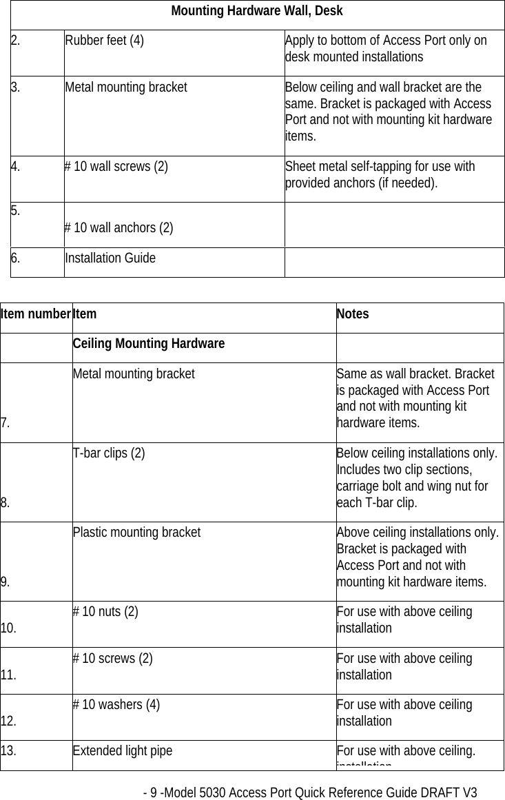
Module Installation
Quick Reference Guide
Navigation menu
Upload a User Manual
Namespaces
Wiki Guide
HTML
PDF
Info
Views
User Manual
Discussion / Help
Navigation