Synapse Electronique ZW01UL Wireless communcation module User Manual
Synapse Electronique Wireless communcation module Users Manual
Users Manual
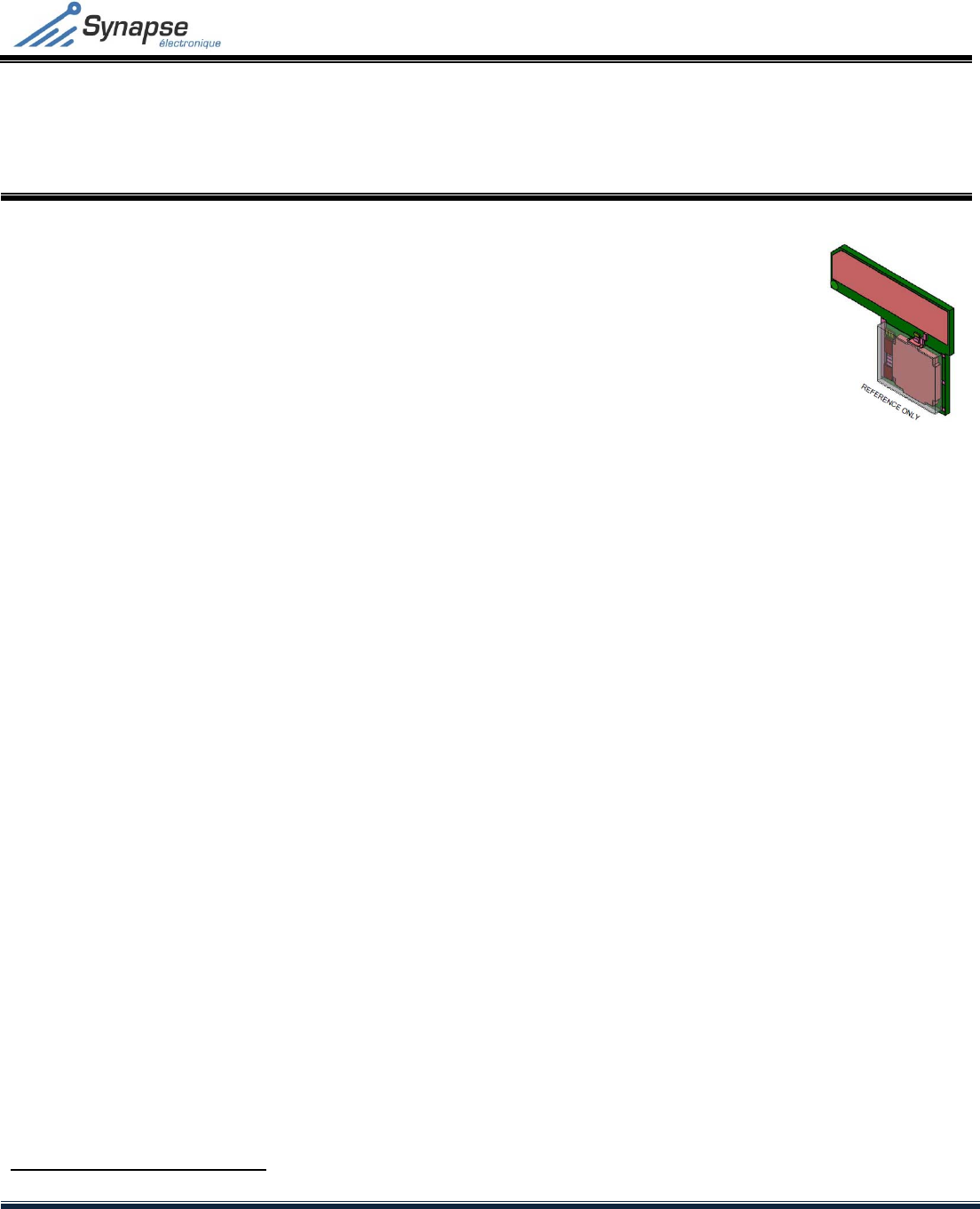
SYN‐RF‐ZW01UxZ‐WAVERADIOMODULE
TECHNICALSPECIFICATION
Rev. 3 – September 015
CONFIDENTIALITY: The information in this document is strictly confidential and is the sole property of Synapse Électronique Inc. This
information may not be reproduced, used or transmitted in any form, in part or in whole, without the written consent of Synapse Électronique Inc.
1/19
Z‐WaveRadioModule
1.1 TECHNICALSUMMARY
FCCcertification:Limitedmodular
FLiRS1mode:lowconsumptionoperation
UARTcommunication:115,200bps
Z‐Wavesoftwareprotocolstackincluded
IntegratedPCBantenna
Outputpower:‐4dBm
CompactPCBfootprint:41x32mm
Basedonan8051CPUcore
Power‐On‐Reset/Brown‐Outdetection
TXmode:typicalcurrent32mAat‐4dBm
RXmode:typicalcurrent32mA
Normalmode:typicalcurrent15mA
Sleepmode:typicalcurrent1µA
1.2 APPLICATIONS
Z‐Waveslaveandenhancedslavemodules
HVACthermostat
Lightswitch‐dimmer
Energymeasurementdevice
Securitysystems
Sensornetworks
Remotecontrolofhouseholdappliances
Audioandvideomanagement
1.3 DESCRIPTION
TheSYN‐RF‐ZW01Uxseriesofmodules
integratesaPCBantennaanda
microcontrollerwithRFtransmitter‐
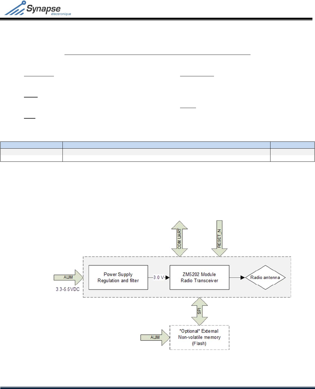
receiver(ZM5202).Anoptionalexternal
non‐volatilememorycanbeadded
accordingtotheZ‐Wavesoftwarestackvariantincludedinthe
module.
Thelimitedmodularcertificationallowstheintegrationofthe
moduleinacompatibleproductwithoutrequiringcertifyingthe
finalproduct.
Toensureareliablecommunication,thepatentedZ‐Wave
protocolsupportsautomaticretransmissions,collision
avoidancemechanisms,frameacknowledgement,CRCs,
frequencyagility,andmeshrouting.
1.4 CERTIFICATION
Limitedmodularcertification
MODEL:SYN‐RF‐ZW01Ux‐L
FCCID:OW7‐ZW01L
IC:10525A‐ZW01UL
1TousethemoduleinFLiRSmode,pleaserefertotheSigmaDesigndocumentation.

SYN‐RF‐ZW01UxZ‐WAVERADIOMODULE
TECHNICALSPECIFICATION
Rev. 3 – September 015
CONFIDENTIALITY: The information in this document is strictly confidential and is the sole property of Synapse Électronique Inc. This
information may not be reproduced, used or transmitted in any form, in part or in whole, without the written consent of Synapse Électronique Inc.
2/19
TABLEOFCONTENT
1.1TECHNICALSUMMARY.............................................................................................................................................................1
1.2APPLICATIONS..........................................................................................................................................................................1
1.3DESCRIPTION............................................................................................................................................................................1
1.4CERTIFICATION.........................................................................................................................................................................1
2Nomenclature...............................................................................................................................................................................3
3FUNCTIONALBLOCKDIAGRAM....................................................................................................................................................3
4PINMAP........................................................................................................................................................................................4
5ELECTRICSPECIFICATIONS............................................................................................................................................................5
5.1Absolutemaximalratings.........................................................................................................................................................5
5.2Recommendedoperatingconditions.......................................................................................................................................5
5.3Electricalspecifications............................................................................................................................................................5
5.4Radiospecifications(RF)...........................................................................................................................................................6
5.5Resettingthemodule...............................................................................................................................................................6
5.6Unusedpins..............................................................................................................................................................................7
5.7Modulecommunication...........................................................................................................................................................7
6EXTERNALNON‐VOLATILEMEMORY(Flash)................................................................................................................................8
7INTEGRATIONGUIDELINES.........................................................................................................................................................10
7.1Environmentalconsiderations................................................................................................................................................10
7.2Soldering.................................................................................................................................................................................10
7.3Connectiondiagramexamples...............................................................................................................................................11
8Mechanicinformation................................................................................................................................................................12
8.1PCBfootprint..........................................................................................................................................................................12
8.2Moduledimensions................................................................................................................................................................13
9FCCComplianceStatement........................................................................................................................................................14
10ICComplianceStatement...........................................................................................................................................................15
11ModificationHISTORY.................................................................................................................................................................16
ANNEXES..................................................................................................................................................................................................
17
1INTEGRATIONconsiderationsfortheSTE402NP+thermostat...................................................................................................18
1.1Mechanicconsiderations........................................................................................................................................................18
1.2PCBintegrationconsiderations..............................................................................................................................................18
2integrationconsiderationsintheSTE‐CIR034heatingConvector..............................................................................................19
2.1Mechanicconsiderations........................................................................................................................................................19
2.2PCBintegrationconsiderations..............................................................................................................................................19
SYN‐RF‐ZW01UxZ‐WAVERADIOMODULE
TECHNICALSPECIFICATION
Rev. 3 – September 015
CONFIDENTIALITY: The information in this document is strictly confidential and is the sole property of Synapse Électronique Inc. This
information may not be reproduced, used or transmitted in any form, in part or in whole, without the written consent of Synapse Électronique Inc.
3/19
2 NOMENCLATURE
SYN‐RF‐ ZW01URS‐ L
12345
1. Functionality
SYN‐RF:Radioproduct
2. Series
ZW01:Z‐Waveprotocol,series01
3. Zone
U:US/CANzone(908MHz)
4. Softwarestack
RS:Routingslave
ES:Enhancedroutingslave
5. Option
L:Limitedmodularcertification
ModelDescriptionZone
*
SYN‐RF‐ZW01URS‐LZ‐Waveradiomodule–routingslavesoftwareconfigurationU
SYN‐RF‐ZW01UES‐LZ‐Waveradiomodule–enhancedroutingslavesoftwareconfigurationU
Table1–Availableoptions
3 FUNCTIONALBLOCKDIAGRAM
Figure1–Blockdiagram‐SYN‐RF‐ZW01Uxmodule
SYN‐RF‐ZW01UxZ‐WAVERADIOMODULE
TECHNICALSPECIFICATION
Rev. 3 – September 015
CONFIDENTIALITY: The information in this document is strictly confidential and is the sole property of Synapse Électronique Inc. This
information may not be reproduced, used or transmitted in any form, in part or in whole, without the written consent of Synapse Électronique Inc.
4/19
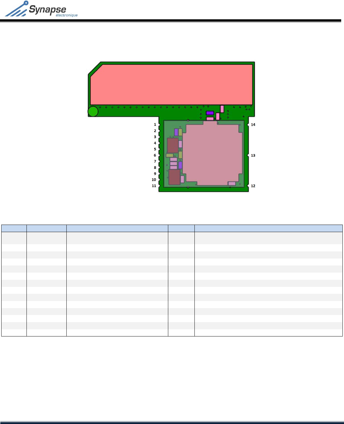
4 PINMAP
Figure2–Pinmap
Pin#NameMCUPinTypeDescription
1RESET_NRESETfunctionisactiveonlowlevel
–
defaultto ahighlevelvia a10K
Ohmpull‐upresistorembeddedinthemodule
2GND1 GND Powersupplyandcircuitground
3NVM_SCKP2.4/SPI1_SCKSPIserialmemory port
–
Dataclocksignal
4NVM_MOSIP2.2/SPI1_MOSISPIserialmemoryport
–
Datasignal,module toexternalmemory
5NVM_MISOP2.3/SPI1_MISOSPIserialmemory port
–
Datasignal,externalmemorytomodule
6NVM_CSP0.4I/O SPIserialmemory port
–
Memoryselection(enable)
7GND2 GND Powersupplyandcircuitground
8UART_B2RFP3.4/UART0_RXUARTserialcommunicationport
–
Datasignal,mastertomodule
9UART_RF2BP3.5/UART0_TXUARTserialcommunicationport
–
Datasignal,moduletomaster
10GND3 GND Powersupplyandcircuitground
11VCC VCC Power rail
12GND4 GND Powersupplyandcircuitground
13GND5 GND Powersupply andcircuitground
14GND6 GND Powersupplyandcircuitground
Table2‐Pinmap
SYN‐RF‐ZW01UxZ‐WAVERADIOMODULE
TECHNICALSPECIFICATION
Rev. 3 – September 015
CONFIDENTIALITY: The information in this document is strictly confidential and is the sole property of Synapse Électronique Inc. This
information may not be reproduced, used or transmitted in any form, in part or in whole, without the written consent of Synapse Électronique Inc.
5/19
5 ELECTRICSPECIFICATIONS
5.1 Absolutemaximalratings
SymbolSettingsMinTypicalMaxUnits
VDD‐GNDSupplyvoltage3.2‐ 6VDC
VIN‐GNDVoltageappliedonaninput‐0.5‐ 6VDC
TSTORStoragetemperature‐55‐ 85
°
C
TAMBOperatingambienttemperature‐40‐ 85
°
C
Table3–Absolutemaximalratings2
5.2 Recommendedoperatingconditions
SymbolSettingsMinTypicalMaxUnits
VDD‐GNDSupplyvoltage3.3‐ 5.5VDC
VIN‐GNDVoltageappliedonaninput0‐5.5VDC
VRIPPLEMaximumsupplyvoltageripple‐ ‐ 0.1∆V
TAMBOperatingambienttemperature‐102580°C
Table4–Recommendedoperatingconditions
5.3 Electricalspecifications
SymbolParameterMinTypicalMaxUnits
VIHHigh‐levelthresholdvoltage,digitalinput2.2‐ ‐ V
VILLow‐levelthresholdvoltage,digitalinput‐‐0.6V
VIL_RESETLow‐levelthresholdvoltage,RESET_Ninput‐ ‐ 0.9V
IILLeakagecurrent,anydigitalinput‐‐10µA
PUINInternalpull‐upresistor,anydigitalinputexceptRESET_N15‐ 20kΩ
PUIN_RESETInternalpull‐upresistor,RESET_Ninput9.910.010.1kΩ
VOHHigh‐levelvoltage,digitaloutputport2.43.03.06V
VOLLow‐levelvoltage,digitaloutputport‐‐0.4V
IOMaximumcurrent,digitaloutputport‐ ‐ 6mA
IDD_ACTIVESupplycurrent,processorclockedat32MHz‐14.915.9mA
IDD_RXSupplycurrent,Z‐Wavereceiving‐ 32.435.1mA
IDD_TX_‐4Supplycurrent,Z‐Wavtransmissionat‐4dBm‐32‐mA
IDD_SLEEPSupplycurrent,sleepmode,wake‐uptimerinactive‐ 1‐ µA
IDD_WUTSupplycurrent,sleepmode,wake‐uptimeractive‐2‐µA
Table5–Electricalspecifications
2Theabsolutemaximalcharacteristicsmustnotbeexceededunderanycircumstance.Exceedingtheselimitscouldcausepermanentdamagetothemodule.
SYN‐RF‐ZW01UxZ‐WAVERADIOMODULE
TECHNICALSPECIFICATION
Rev. 3 – September 015
CONFIDENTIALITY: The information in this document is strictly confidential and is the sole property of Synapse Électronique Inc. This
information may not be reproduced, used or transmitted in any form, in part or in whole, without the written consent of Synapse Électronique Inc.
6/19
5.4 Radiospecifications(RF)
Datarate9.6kbps40kbps100kbpsZone
ModulationFSKFSKGFSK
FrequencydeviationFC±20kHzFC±20kHzFC±29.3kHz
Channelbandwidth90kHz90kHz110kHz
EncodingManchesterencodedNRZNRZ
Frequency(Canada/US)908.42MHz908.40MHz916MHzU
Table6–Z‐Waveradiofrequencyspecifications
SymbolSettingsMinTypicalMaxUnits
P9.6Sensibilityat9.6kbps‐ ‐102.7‐101.0dBm
P40Sensibilityat40kbps‐ ‐99.0‐97.2dBm
P100Sensibilityat100kbps‐ ‐93.0‐91.8dBm
Table7–Receiversensibility(excludingtheantenna)
SymbolSettingsMinTypicalMaxUnits
PRFCurrenttransmitterpower(RFPOW=17,0x11)‐ ‐4‐ dBm
PH2Secondharmonic(RFPOW=20(‐3dBm))‐‐59.6‐ dBc
PH3Thirdharmonic(RFPOW=20(‐3dBm))‐ ‐47.6‐ dBc
PN30kHzPhasenoiseat30kHz‐ ‐88.1‐dBc/Hz
PN100kHzPhasenoiseat100kHz‐ ‐95.2‐ dBc/Hz
PN1MHzPhasenoiseat1MHz‐ ‐107.3‐dBc/Hz
PN10MHzPhasenoiseat10MHz‐ ‐113.1‐ dBc/Hz
PN100MHzPhasenoiseat100MHz‐ ‐113.8‐dBc/Hz
Table8–Transmitterperformances(excludingtheantenna)
5.5 Resettingthemodule
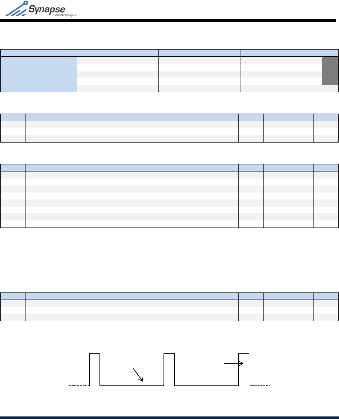
ThemoduleisresetbypulsingtheRESET_Ninputlowonetime,aspertheTReset_LspecificationinTable9.Tokeepthemodulein
'reset',theRESET_NinputmustbecontinuouslypulsedasperthespecificationsinTable9.
SymbolSettings MinTypicalMax Units
TReset_LHoldtime,RESET_Nlow3‐ 4,000us
TReset_HHoldtime,RESET_Nhigh2‐4us
TReset_PUMaximumtimeafteraresettoreturninactivemodeandbereadytoexecutethesoftware‐ ‐ 1ms
Table9–Resetmode
Figure3–PulsingtheRESET_Ninputtomaintaintheresetmode
TReset_LTReset_H

SYN‐RF‐ZW01UxZ‐WAVERADIOMODULE
TECHNICALSPECIFICATION
Rev. 3 – September 015
CONFIDENTIALITY: The information in this document is strictly confidential and is the sole property of Synapse Électronique Inc. This
information may not be reproduced, used or transmitted in any form, in part or in whole, without the written consent of Synapse Électronique Inc.
7/19
TheRESET_Ninputofthemodulemustbedrivenbyanopencollectorcircuit.Drivingthisinputwithapush‐pullcircuitcould
damagethemodule.TheRESET_Ninputintegratesapull‐upresistortomaintainthisinputhighwhennotdriven.
Donotaddanyexternalfilteronthisport;themodulealreadyincludesafilter.
5.6 Unusedpins
Allunusedpinsmustbeleftunconnected.Theredefaultlevelisinternallyfixedat3.0Vtypicalonthemodule.Theonlyexceptionis
theMISOinputportthatmustbeconnectedtoGNDwhenunused
5.7 Modulecommunication
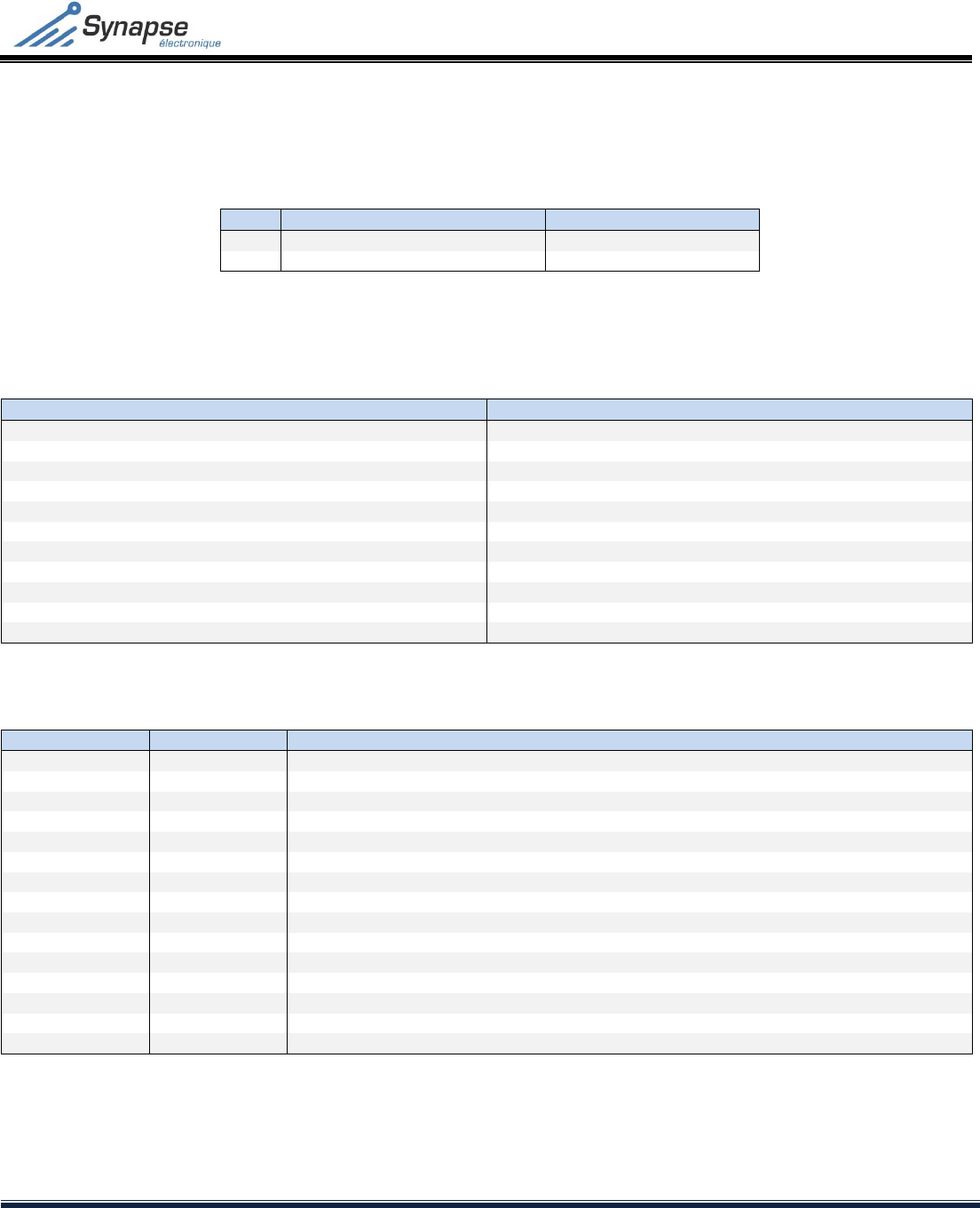
ThecommunicationwiththemoduleisperformedviatheserialUART(UniversalAsynchronousReceiver/Transmitter),usingthe
UART_RF2BandUART_B2RFports.TheUARToperatingspecificationsmustbeconfiguredasperTable10andFigure4.
Settings Value
Bitspersecond115200
Databits8
Paritynon
Stopbit1
Flowcontrolnon
Table10–UARTconfigurationsettings
Figure4–UARTcommunicationwaveform
SYN‐RF‐ZW01UxZ‐WAVERADIOMODULE
TECHNICALSPECIFICATION
Rev. 3 – September 015
CONFIDENTIALITY: The information in this document is strictly confidential and is the sole property of Synapse Électronique Inc. This
information may not be reproduced, used or transmitted in any form, in part or in whole, without the written consent of Synapse Électronique Inc.
8/19
6 EXTERNALNON‐VOLATILEMEMORY(FLASH)
DependingontheZ‐Wavenetworktypedesired,themodulemayrequireanexternalmemorytooperate.
CodeSoftwarestackExternalmemoryneeded
RSRoutingSlaveNo
ESEnhancedRoutingSlaveYes
Table11–Externalmemoryrequirement
Inthecaseofanenhancedroutingslaveapplication,thememoryneededshallmeetthefollowingrequirements:
SettingsValue
Size1Mbits
SPImodessupported(CPOL=0,SPHA=0)&(CPOL=1,CPHA=1)
SPIclockfrequency4MHz
PageWritesize256Bytes
PageErasesize256Bytes
SoftwareprotectionYes
PageRead85µs
PageWritecycle25ms
Endurance100000cyclestypical
DataRetention>20years
Temperature‐40°Cto85°C
Table12–SerialFlashmemoryspecifications
CommandOpcodeDescription
WREN0x06WriteEnable
WRDI0x04WriteDisable
RDID0x9FReadIdentification
RDSR0x05ReadStatusRegister
WRSR0x01WriteStatusRegister
READ0x03ReadDataBytes
FAST_READ0x0BReadDataBytesatHigherSpeed
PW0x0APageWrite(256B)
PP0x02PageProgram
PE0xDBPageErase(256B)
SSE0x20Sub‐SectorErase
SE0xD8SectorErase
BE0xC7BulkErase
DP0xB9DeepPower‐down
RDP0xABReleasefromDeepPower‐down
Table13–Flashmemoryinstructions

SYN‐RF‐ZW01UxZ‐WAVERADIOMODULE
TECHNICALSPECIFICATION
Rev. 3 – September 015
CONFIDENTIALITY: The information in this document is strictly confidential and is the sole property of Synapse Électronique Inc. This
information may not be reproduced, used or transmitted in any form, in part or in whole, without the written consent of Synapse Électronique Inc.
9/19
BitNameDescription
7SRWDStatusRegisterWriteDisable
6,5,4XUndefined
3BP1BlockProtect1
2BP0BlockProtect0
1WELWriteEnableLatch
0WIPWriteinProgress
Table14–Flashmemorystatusregisters
SynapseElectronicsrecommendsthefollowingmemorymodelthatmeetstherequirements.
TypeManufacturer Partnumber Memoryspace
FlashMicronTechnologyM25PE20256kB
Table15–Externalmemoryrecommended

SYN‐RF‐ZW01UxZ‐WAVERADIOMODULE
TECHNICALSPECIFICATION
Rev. 3 – September 015
CONFIDENTIALITY: The information in this document is strictly confidential and is the sole property of Synapse Électronique Inc. This
information may not be reproduced, used or transmitted in any form, in part or in whole, without the written consent of Synapse Électronique Inc.
10/19
7 INTEGRATIONGUIDELINES
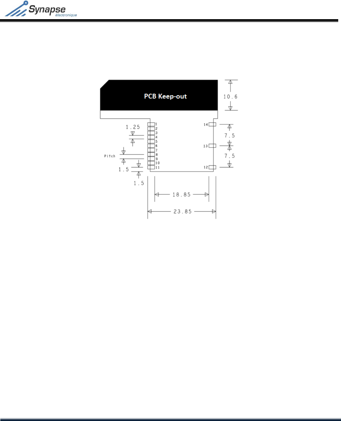
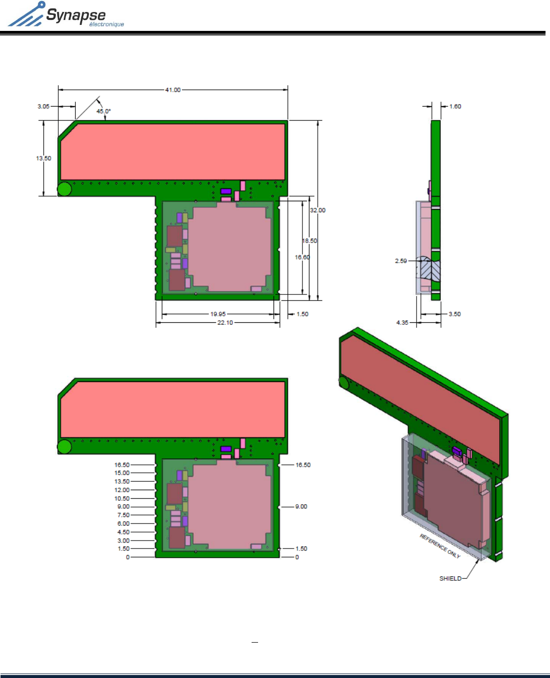
TheSYN‐RF‐ZM01Uxisasurfacemountmodule.ItsshapeanddimensionsareillustratedinFigure8.ThePCBhasathicknessof1.6
mmandaninterconnectionfootprintofcastellationtype.Figure7illustratestherecommendedPCBfootprint.
APCBantennaisintegratedonthemodule.ThegroundplaneofthemasterPCB(receivingthemodule)actsasacounterbalancefor
thePCBantenna.Thegroundplane’sdimensionshaveamajorimpactontheantennaperformance.Itisrecommendedtomaximize
thesurfaceofthisgroundplaneonthemasterPCB.
AllGNDpinsshallbedirectlyconnectedtothegroundplaneofthemasterPCB.Ifthermal‐reliefconnexionviasareused,the
combinedwidthshallbenolessthan0.5mm.
7.1 Environmentalconsiderations
Theradioperformancesofthemodulearegreatlyaffectedbyitsenvironment.Theannexesattheendofthisdocumentprovide
guidelinestointegratethemoduleindifferentmasterproducts.Theintegrationofthismoduleinproductsotherthantheones
presentedwouldrequirecarefulverificationoftheradioperformancesandcharacterization.
7.2 Soldering
Themodulemustbehandsoldered.Ithasnotbeendesignedforreflowsoldering,asitcouldresultinapermanentdamageofthe
module.
SYN‐RF‐ZW01UxZ‐WAVERADIOMODULE
TECHNICALSPECIFICATION
Rev. 3 – September 015
CONFIDENTIALITY: The information in this document is strictly confidential and is the sole property of Synapse Électronique Inc. This
information may not be reproduced, used or transmitted in any form, in part or in whole, without the written consent of Synapse Électronique Inc.
11/19
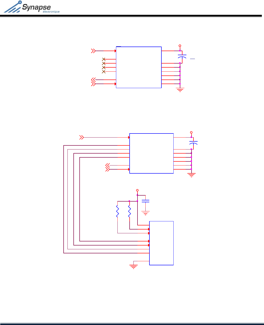
7.3 Connectiondiagramexamples
Figure5–Connectionwithoutexternalmemory
Figure6–Connectionwithexternalmemory
3.3V
UART_B2RF
UART_RF2B
RESET_N
C1
1 uF
U1
SYN-RF-ZM01xx
RESET_N
1
UART_B2RF
8UART_RF2B
9
VDD 11
GND1 2
GND2 7
GND3 10
GND4 12
GND5 13
GND6 14
NVM_SCK
3
NVM_MOSI
4
NVM_MISO
5
NVM_CS
6
3.3V
UART_B2RF
UART_RF2B
RESET_N
C1
1 uF
U1
SYN-RF-ZM01xx
RESET_N
1
UART_B2RF
8UART_RF2B
9
VDD 11
GND1 2
GND2 7
GND3 10
GND4 12
GND5 13
GND6 14
NVM_SCK
3
NVM_MOSI
4
NVM_MISO
5
NVM_CS
6
C2
R1 R2
U2
External NVM
CS#
1
HOLD#
7
SI/SIO0
5
SCLK
6
VCC
8
GND
4
SO/SIO1
2
WP#
3
3.3V
SYN‐RF‐ZW01UxZ‐WAVERADIOMODULE
TECHNICALSPECIFICATION
Rev. 3 – September 015
CONFIDENTIALITY: The information in this document is strictly confidential and is the sole property of Synapse Électronique Inc. This
information may not be reproduced, used or transmitted in any form, in part or in whole, without the written consent of Synapse Électronique Inc.
12/19
8 MECHANICINFORMATION
8.1 PCBfootprint
Figure7–RecommendedPCBfootprint
Notes:
1. Dimensionsareinmm;
2. NomaterialmustbeinthePCBkeep‐outzone,includingFR4dielectric.PerformanopeninginthemasterPCB,orplacethe
moduleinperiphery,withthekeep‐outzonelyingoutsidethemasterPCB;
3. Themoduleincludesviasonitsbottomlayer,facingthemasterPCB.Makesurethatthereisnoconductivematerial
exposedonthemasterPCB,underthemodule.Exposedconductivematerialcouldcauseashortcircuitonthemoduleor
themasterPCB,andpotentiallydamagethem.
Thesolderjointbetweenthemodule'scastellatedpadsandthemasterPCBpadsshallmeettheappropriateIPCrequirements.
Pleaserefertothedocument'IPC‐A‐610AcceptabilityofElectronicAssemblies',section8.2.4CastellatedTerminations.
SYN‐RF‐ZW01UxZ‐WAVERADIOMODULE
TECHNICALSPECIFICATION
Rev. 3 – September 015
CONFIDENTIALITY: The information in this document is strictly confidential and is the sole property of Synapse Électronique Inc. This
information may not be reproduced, used or transmitted in any form, in part or in whole, without the written consent of Synapse Électronique Inc.
13/19
8.2 Moduledimensions
Figure8–Moduledimensionsinmm
Note:TheshieldingboxisnotincludedintheSYN‐RF‐ZW01Ux‐Lversions.

SYN‐RF‐ZW01UxZ‐WAVERADIOMODULE
TECHNICALSPECIFICATION
Rev. 3 – September 015
CONFIDENTIALITY: The information in this document is strictly confidential and is the sole property of Synapse Électronique Inc. This
information may not be reproduced, used or transmitted in any form, in part or in whole, without the written consent of Synapse Électronique Inc.
14/19
9 FCCCOMPLIANCESTATEMENT
FCCWarning
NOTE:ThisequipmenthasbeentestedandfoundtocomplywiththelimitsforaClassBdigitaldevice,pursuanttoPart15oftheFCC
Rules.Theselimitsaredesignedtoprovidereasonableprotectionagainstharmfulinterferenceinaresidentialinstallation.
Thisequipmentgenerates,usesandcanradiateradiofrequencyenergyand,ifnotinstalledandusedinaccordancewiththe
instructions,maycauseharmfulinterferencetoradiocommunications.
However,thereisnoguaranteethatinterferencewillnotoccurinaparticularinstallation.Ifthisequipmentdoescauseharmful
interferencetoradioortelevisionreception,whichcanbedeterminedbyturningtheequipmentoffandon,theuserisencouraged
totrytocorrecttheinterferencebyoneormoreofthefollowingmeasures:
Reorientorrelocatethereceivingantenna.
Increasetheseparationbetweentheequipmentandreceiver.
Connecttheequipmentintoanoutletonacircuitdifferentfromthattowhichthereceiverisconnected.
Consultthedealeroranexperiencedradio/TVtechnicianforhelp.
Caution
Thisdevicecomplieswithpart15oftheFCCRules.Operationissubjecttothefollowingtwoconditions:
1. Thisdevicemaynotcauseharmfulinterference,and
2. Thisdevicemustacceptanyinterferencereceived,includinginterferencethatmaycauseundesiredoperation.
Changesormodificationsnotexpresslyapprovedbythepartyresponsibleforcompliancecouldvoidtheuser'sauthoritytooperate
theequipment.

SYN‐RF‐ZW01UxZ‐WAVERADIOMODULE
TECHNICALSPECIFICATION
Rev. 3 – September 015
CONFIDENTIALITY: The information in this document is strictly confidential and is the sole property of Synapse Électronique Inc. This
information may not be reproduced, used or transmitted in any form, in part or in whole, without the written consent of Synapse Électronique Inc.
15/19
10 ICCOMPLIANCESTATEMENT
ThisdevicecomplieswithIndustryCanadalicense‐exemptRSSstandard(s).Operationissubjecttothefollowingtwoconditions:
1. Thisdevicemaynotcauseinterference,and;
2. Thisdevicemustacceptanyinterference,includinginterferencethatmaycauseundesiredoperationofthedevice.
LeprésentappareilestconformeauxCNRd'IndustrieCanadaapplicablesauxappareilsradioexemptsdelicence.L'exploitationest
autoriséeauxdeuxconditionssuivantes:
1. L'appareilnedoitpasproduiredebrouillage,et;
2. L'utilisateurdel'appareildoitacceptertoutbrouillageradioélectriquesubi,mêmesilebrouillageestsusceptibled'en
compromettrelefonctionnement.
UnderIndustryCanadaregulations,thisradiotransmittermayonlyoperateusinganantennaofatypeandmaximum(orlesser)gain
approvedforthetransmitterbyIndustryCanada.Toreducepotentialradiointerferencetootherusers,theantennatypeandits
gainshouldbesochosenthattheequivalentisotropicallyradiatedpower(e.i.r.p.)isnotmorethanthatnecessaryforsuccessful
communication.
Conformémentàlaréglementationd'IndustrieCanada,leprésentémetteurradiopeutfonctionneravecuneantenned'untypeet
d'ungainmaximal(ouinférieur)approuvépourl'émetteurparIndustrieCanada.Danslebutderéduirelesrisquesdebrouillage
radioélectriqueàl'intentiondesautresutilisateurs,ilfautchoisirletyped'antenneetsongaindesortequelapuissanceisotrope
rayonnéeéquivalente(p.i.r.e.)nedépassepasl'intensiténécessaireàl'établissementd'unecommunicationsatisfaisante.

SYN‐RF‐ZW01UxZ‐WAVERADIOMODULE
TECHNICALSPECIFICATION
Rev. 3 – September 015
CONFIDENTIALITY: The information in this document is strictly confidential and is the sole property of Synapse Électronique Inc. This
information may not be reproduced, used or transmitted in any form, in part or in whole, without the written consent of Synapse Électronique Inc.
16/19
11 MODIFICATIONHISTORY
Rev.DateDescription
0January2015Initialrelease
1April2015Globalupdatefollowingthemodulerevision
2September2015Officialrelease
–
Certificationinformationadded
3September2015Regulatory
–
FCC&IC
–
Statementadded
Table16–Modificationhistory
SynapseÉlectroniqueInc.
1010,7thAvenue,Grand‐Mère
(Quebec)G9T2B8,Canada
Tel:1‐819‐533‐3553
Fax:1‐819‐533‐3577
www.synapseelectronique.com

SYN‐RF‐ZW01UxZ‐WAVERADIOMODULE
TECHNICALSPECIFICATION
Rev. 3 – September 015
CONFIDENTIALITY: The information in this document is strictly confidential and is the sole property of Synapse Électronique Inc. This
information may not be reproduced, used or transmitted in any form, in part or in whole, without the written consent of Synapse Électronique Inc.
17/19
ANNEXES
SYN‐RF‐ZW01UxZ‐WAVERADIOMODULE
TECHNICALSPECIFICATION
Rev. 3 – September 015
CONFIDENTIALITY: The information in this document is strictly confidential and is the sole property of Synapse Électronique Inc. This
information may not be reproduced, used or transmitted in any form, in part or in whole, without the written consent of Synapse Électronique Inc.
18/19
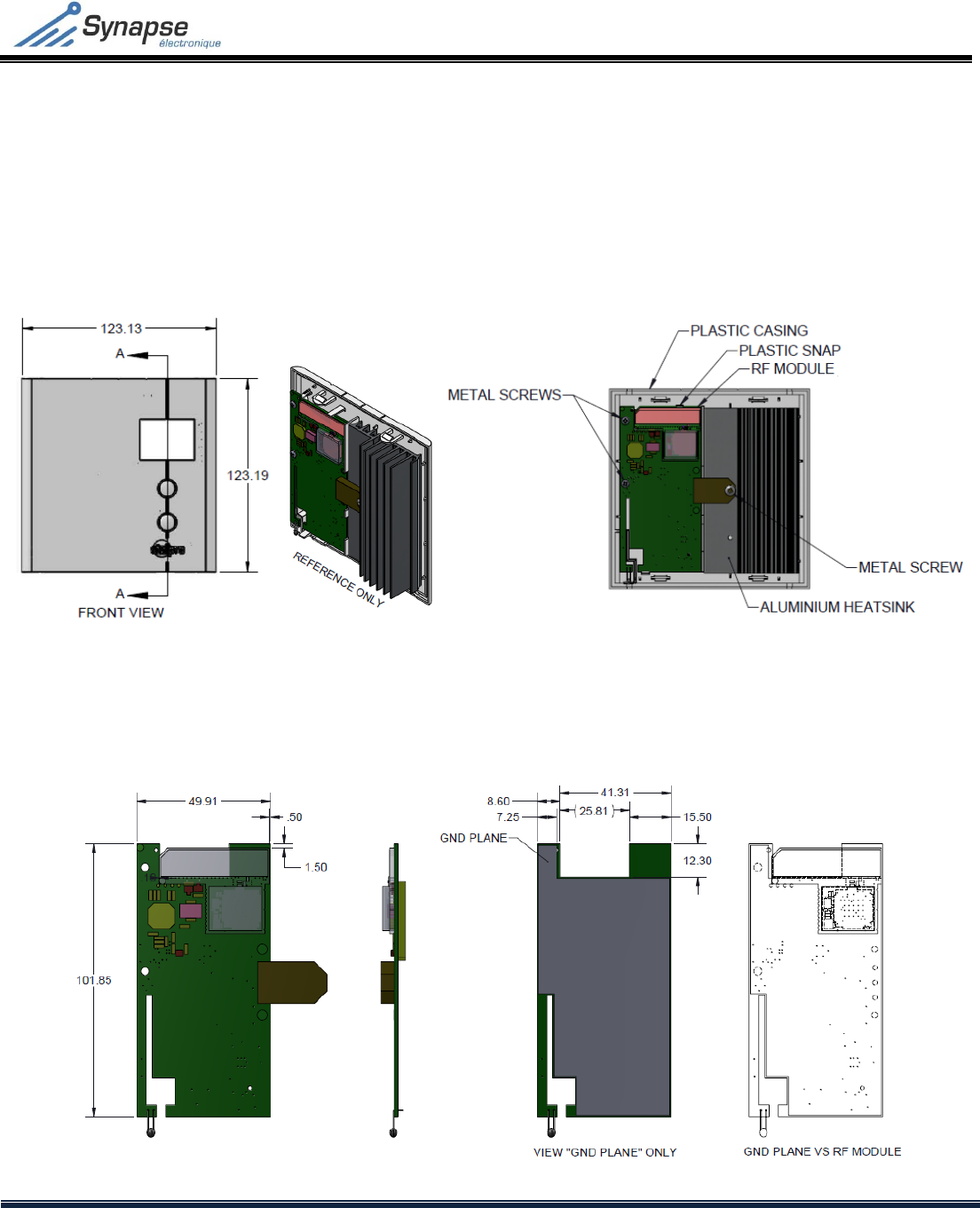
1 INTEGRATIONCONSIDERATIONSFORTHESTE402NP+THERMOSTAT
1.1 Mechanicconsiderations
ThedesignandverificationsontheSTE402NP+thermostatwereperformedinaccordancewiththefollowingspecifications.Doing
otherwisethanindicatedinthissectioncouldnegativelyimpacttheradioperformance.
MechanicintegrationintheSTE402NP+inmm
1.2 PCBintegrationconsiderations
Developmentandtestsweredonewiththelayoutandthegroundplaneillustratedhereunder.Doingotherwisethanindicatedin
thissectioncouldnegativelyimpacttheradioperformance.
ModuleintegrationontheSTE402NP+PCBinmm
SYN‐RF‐ZW01UxZ‐WAVERADIOMODULE
TECHNICALSPECIFICATION
Rev. 3 – September 015
CONFIDENTIALITY: The information in this document is strictly confidential and is the sole property of Synapse Électronique Inc. This
information may not be reproduced, used or transmitted in any form, in part or in whole, without the written consent of Synapse Électronique Inc.
19/19
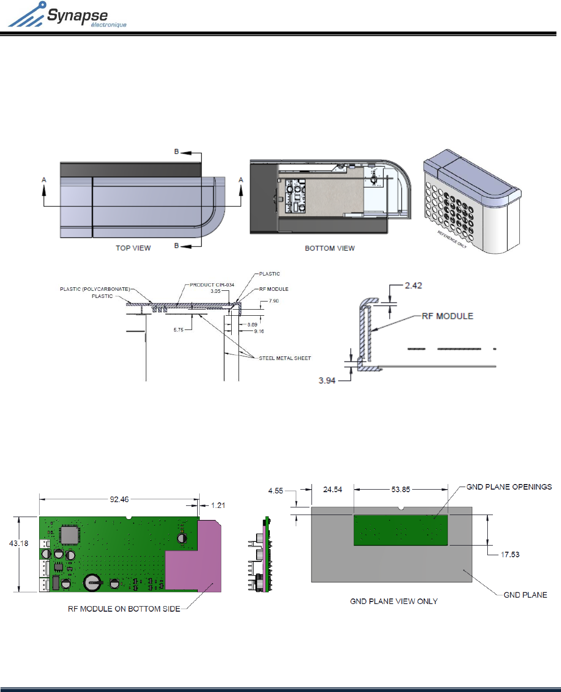
2 INTEGRATIONCONSIDERATIONSINTHESTE‐CIR034HEATINGCONVECTOR
2.1 Mechanicconsiderations
Thedesignandverificationsweredoneaccordingtothefollowingspecifications.Doingotherwisethanindicatedinthissection
couldnegativelyimpacttheradioperformance.
MechanicintegrationintheCIR034(convector)inmm
2.2 PCBintegrationconsiderations
Developmentandtestsweredonewiththelayoutandthegroundplaneillustratedhereunder.Doingotherwisethanindicatedin
thissectioncouldhaveanimpactontheradioperformance.
ModuleintegrationintheCIR‐034heatingconvectorinmm