Synapse Wireless RF200 RF200 Module User Manual My
Synapse Wireless Inc. RF200 Module My
UserManual.wiki
>
Synapse Wireless
>
RF200 User Manual
>
User Manual
Contents
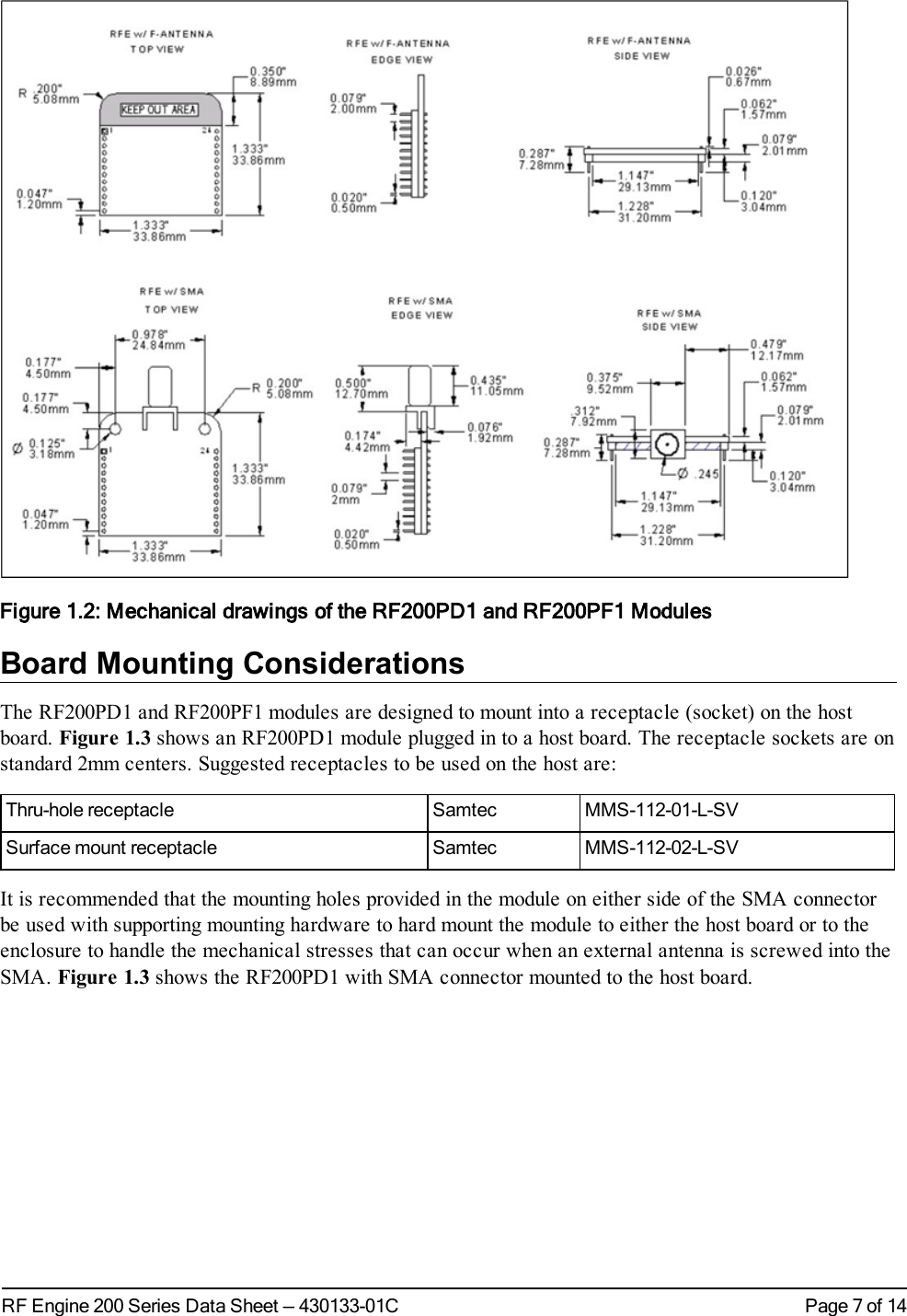
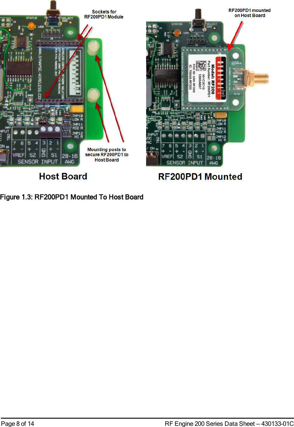
1.
Manual
2.
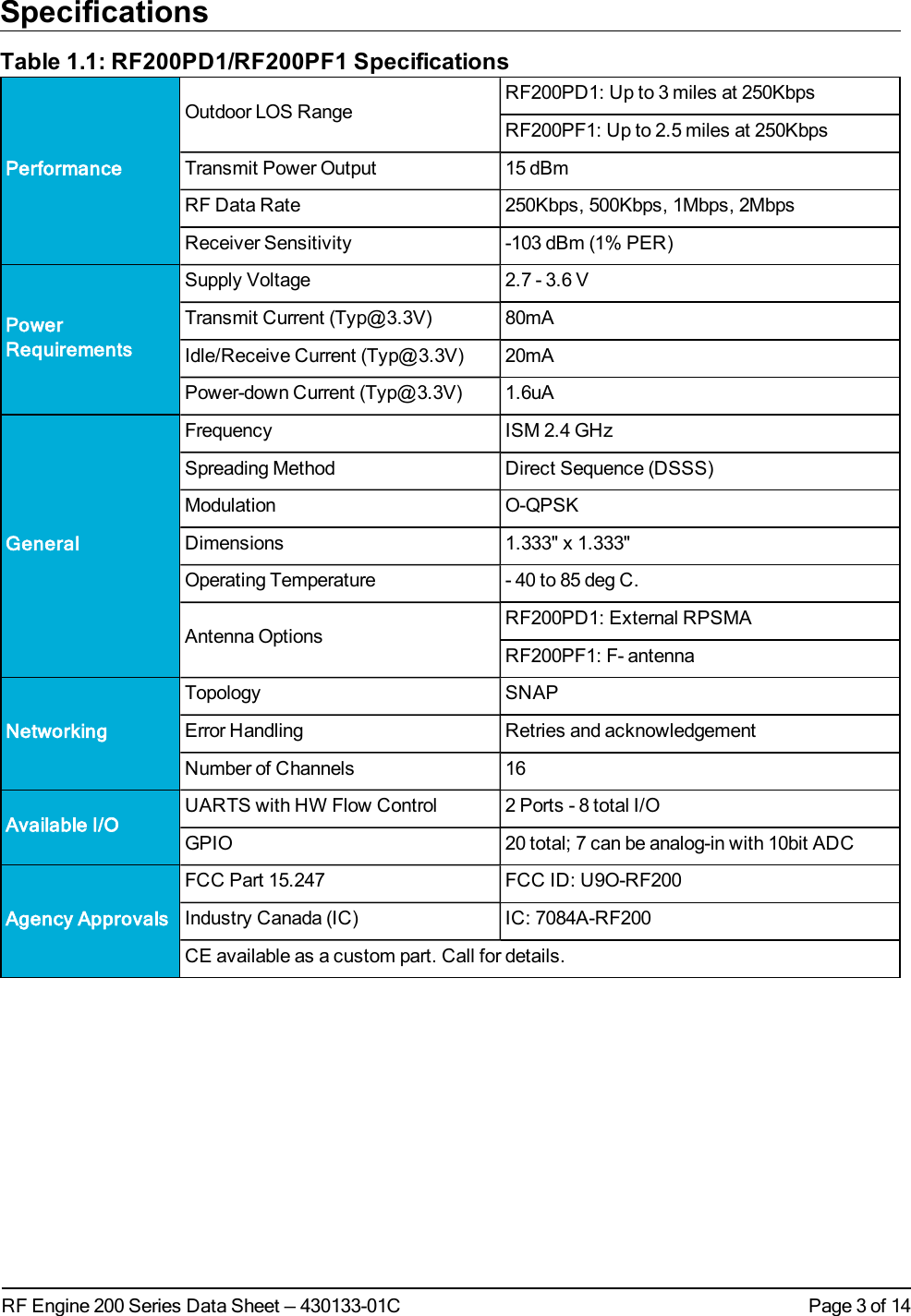
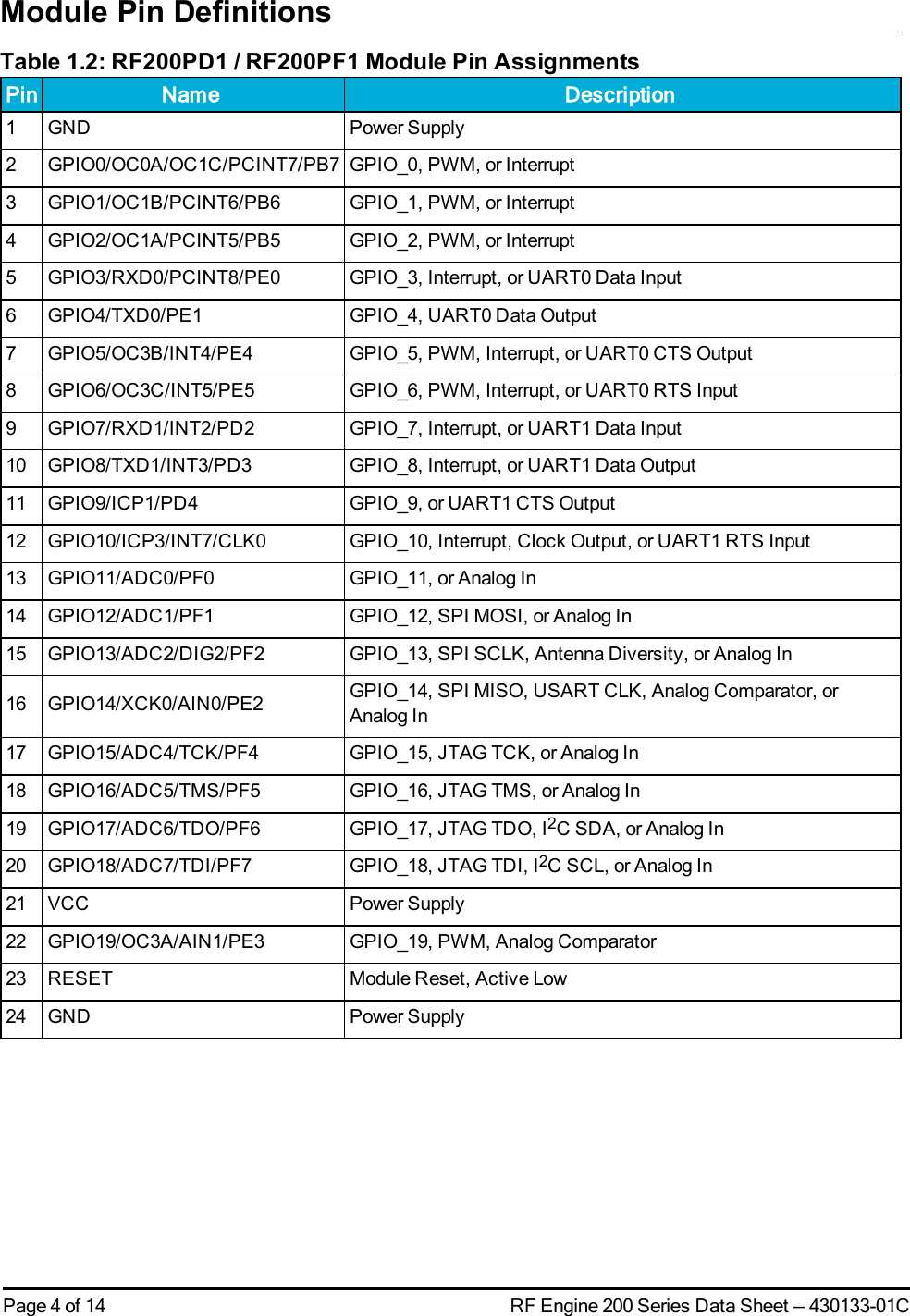
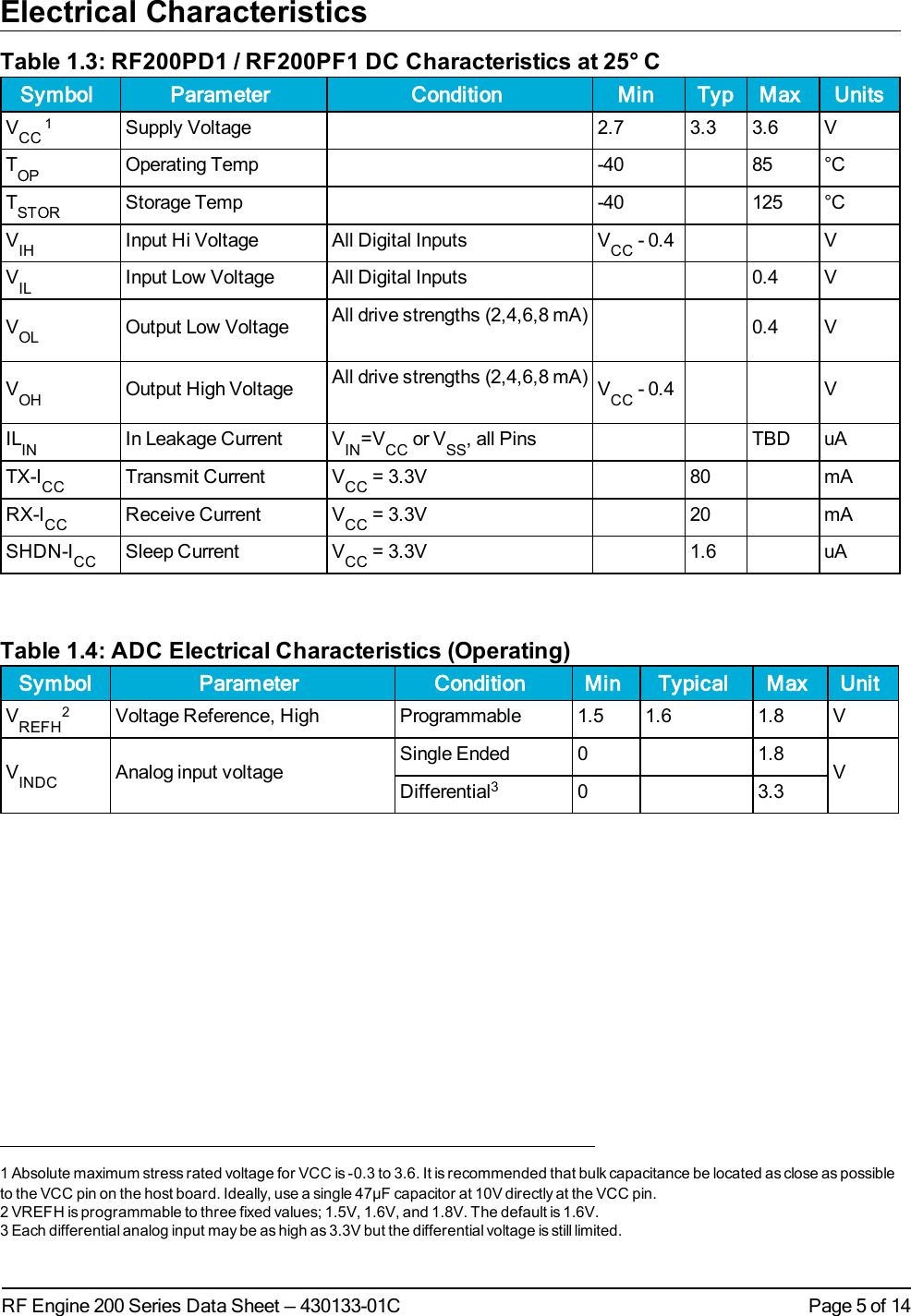
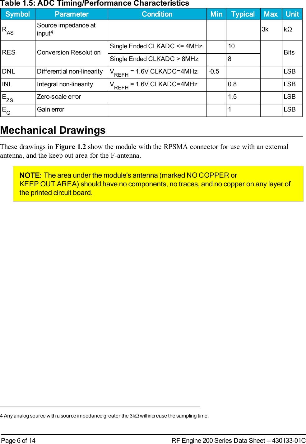
User Manual
User Manual
Navigation menu
Upload a User Manual
Namespaces
Wiki Guide
HTML
PDF
Info
Views
User Manual
Discussion / Help
Navigation