Synapse Wireless RF300 RF300 Module User Manual 10 0403 Exhibit Cover
Synapse Wireless Inc. RF300 Module 10 0403 Exhibit Cover
UserManual.wiki
>
Synapse Wireless
>
RF300 User Manual
Manual
Navigation menu
Upload a User Manual
Namespaces
Wiki Guide
HTML
PDF
Info
Views
User Manual
Discussion / Help
Navigation


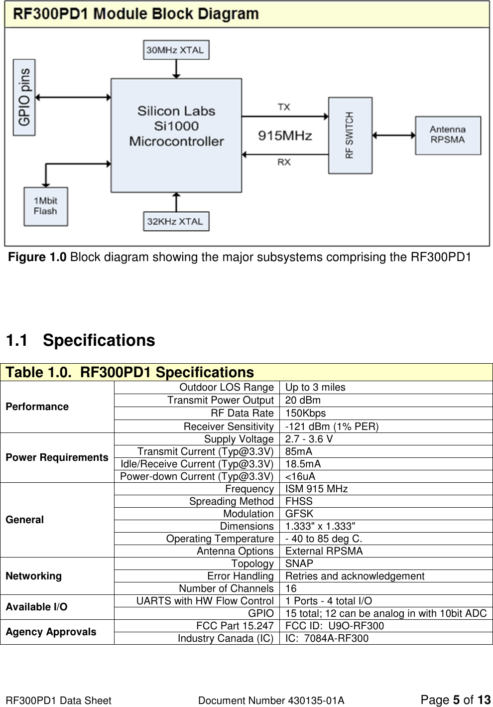
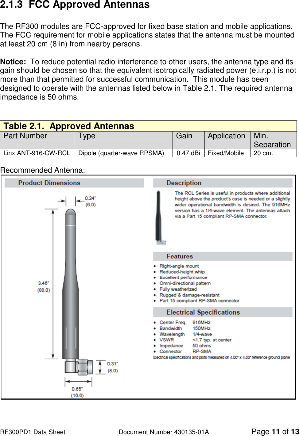
![RF300PD1 Data Sheet Document Number 430135-01A Page 6 of 13 1.2 Module Pin Definitions Table 1.1. RF300PD1 Module Pin Assignments Pin Name Description 1 GND Power Supply 2 GPIO0/ADC17/P2.1 GPIO_0, ADC17, I2C SDA 3 GPIO1/ADC18/P2.2 GPIO_1, ADC18, I2C SCL 4 GPIO2/ADC19/P2.3 GPIO_2, ADC19 5 GPIO3/ADC20/P2.4 GPIO_3, ADC20 6 GPIO4/ADC21/P2.5 GPIO_4, ADC21, SPI MOSI 7 GPIO5/ADC22/P2.6 GPIO_5, ADC22, SPI SCLK 8 GPIO6/ADC0/P0.0/VREF GPIO_6, ADC0, Interrupt, External Voltage Reference, SPI MISO 9 GPIO7/ADC5/P0.5/UART_RX GPIO_7, ADC5, Interrupt, UART0 Rx Data Input 10 GPIO8/ADC4/P0.4/UART_TX GPIO_8, ADC4, Interrupt, UART0 Tx Data Output 11 GPIO9/ADC3/P0.3/CTS GPIO_9, ADC3, UART0 CTS Output 12 GPIO10/ADC2/P0.2/RTS GPIO_10, ADC2, Interrupt, UART0 RTS Input 13 [GPIO11/ADC16/P2.0] Not Available, Do Not Connect1 14 [GPIO12/ADC15/P1.7] Not Available, Do Not Connect1 15 [GPIO13/ADC13/P1.5] Not Available, Do Not Connect1 16 [GPIO14/ADC14/P1.6] Not Available, Do Not Connect1 17 GPIO15/ADC6/P0.6/CNVSTR GPIO_15, ADC6, External “Start Conversion” for ADC0 18 GPIO16/P2.7 GPIO_162 19 GPIO17 GPIO_17 20 ANT_A GPIO_18 (Output Only) 21 VCC Power Supply 22 C2D Background Debug Communications 23 RESET Module Reset, Active Low 24 GND Power Supply 1 Pins 13 – 16 are not available for use on the RF300 and should not be tied to any signals. These pins are used for access to the onboard external memory. 2 GPIO16 has limited drive strength as it is routed through a 1Kohm resistor. The signal driven from (or to) GPIO16 can also be read, or driven, on pin 22 (CD2), the debug pin.](https://usermanual.wiki/Synapse-Wireless/RF300/User-Guide-1686227-Page-7.png)