Synapse Wireless RFE RF ENGINE User Manual USERS MANUAL
Synapse Wireless Inc. RF ENGINE USERS MANUAL
UserManual.wiki
>
Synapse Wireless
>
RFE User Manual
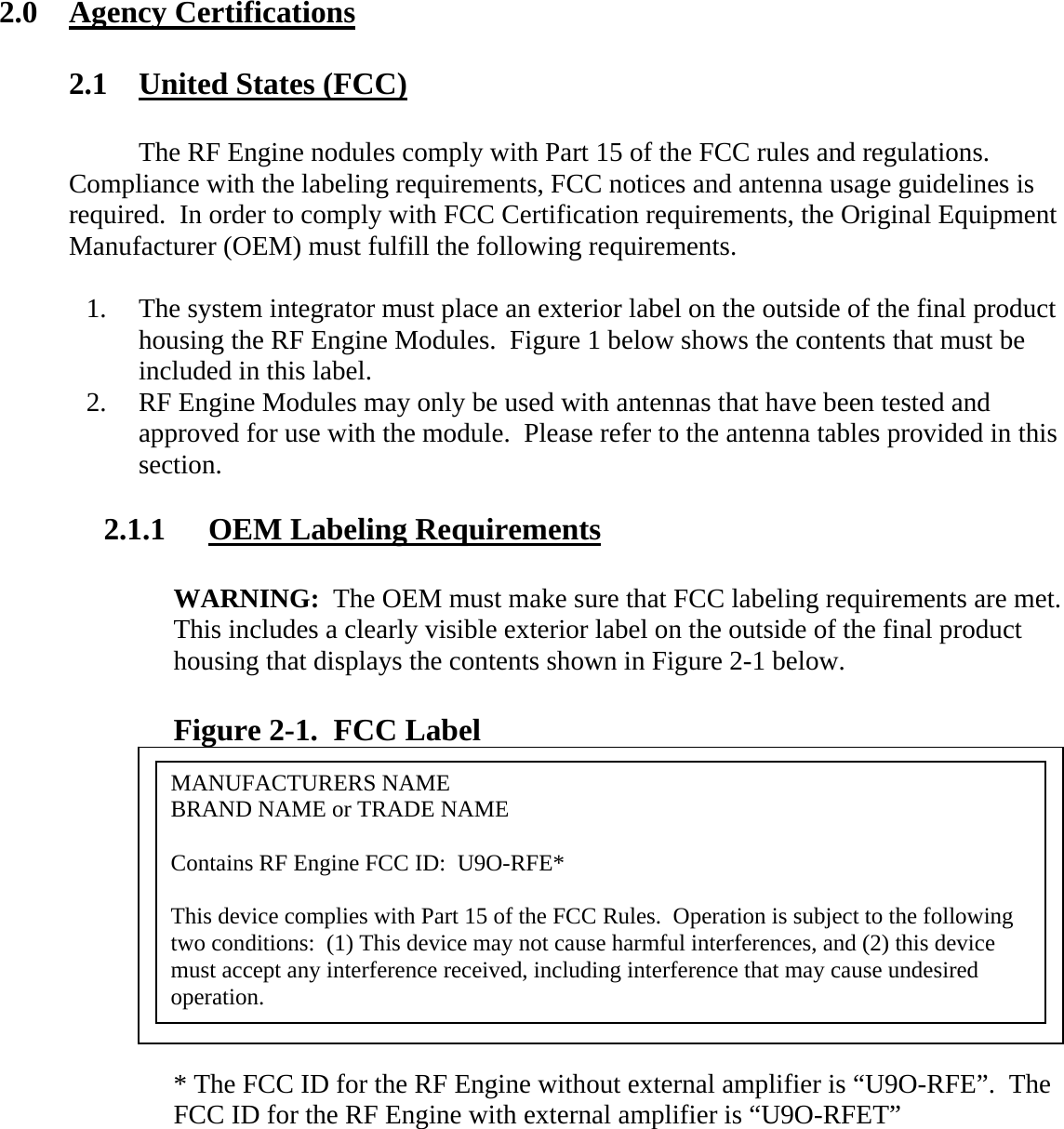
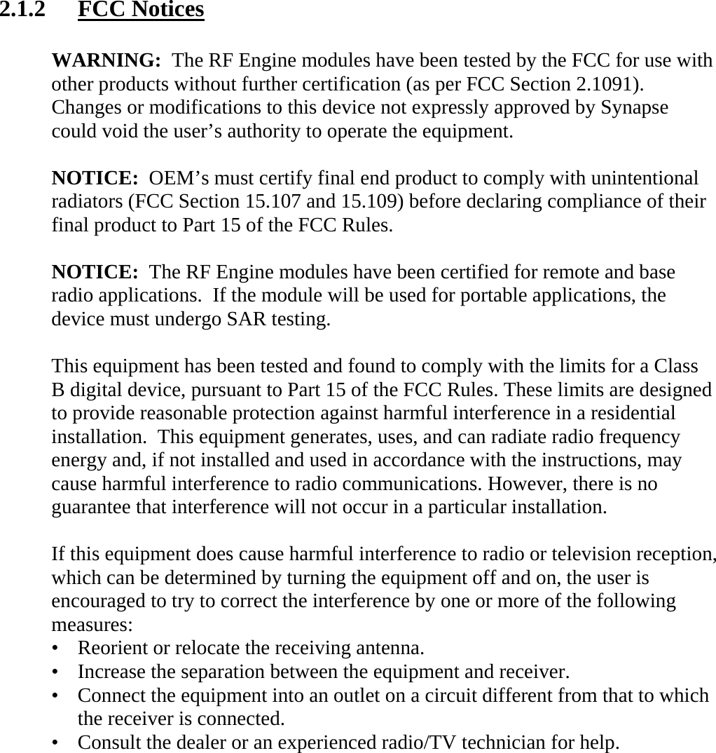
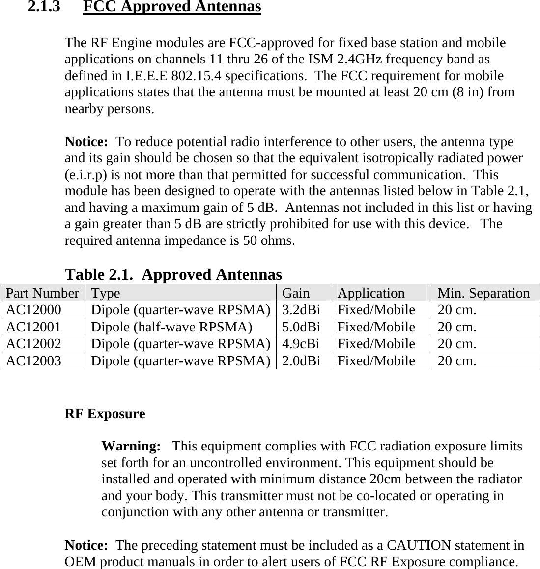
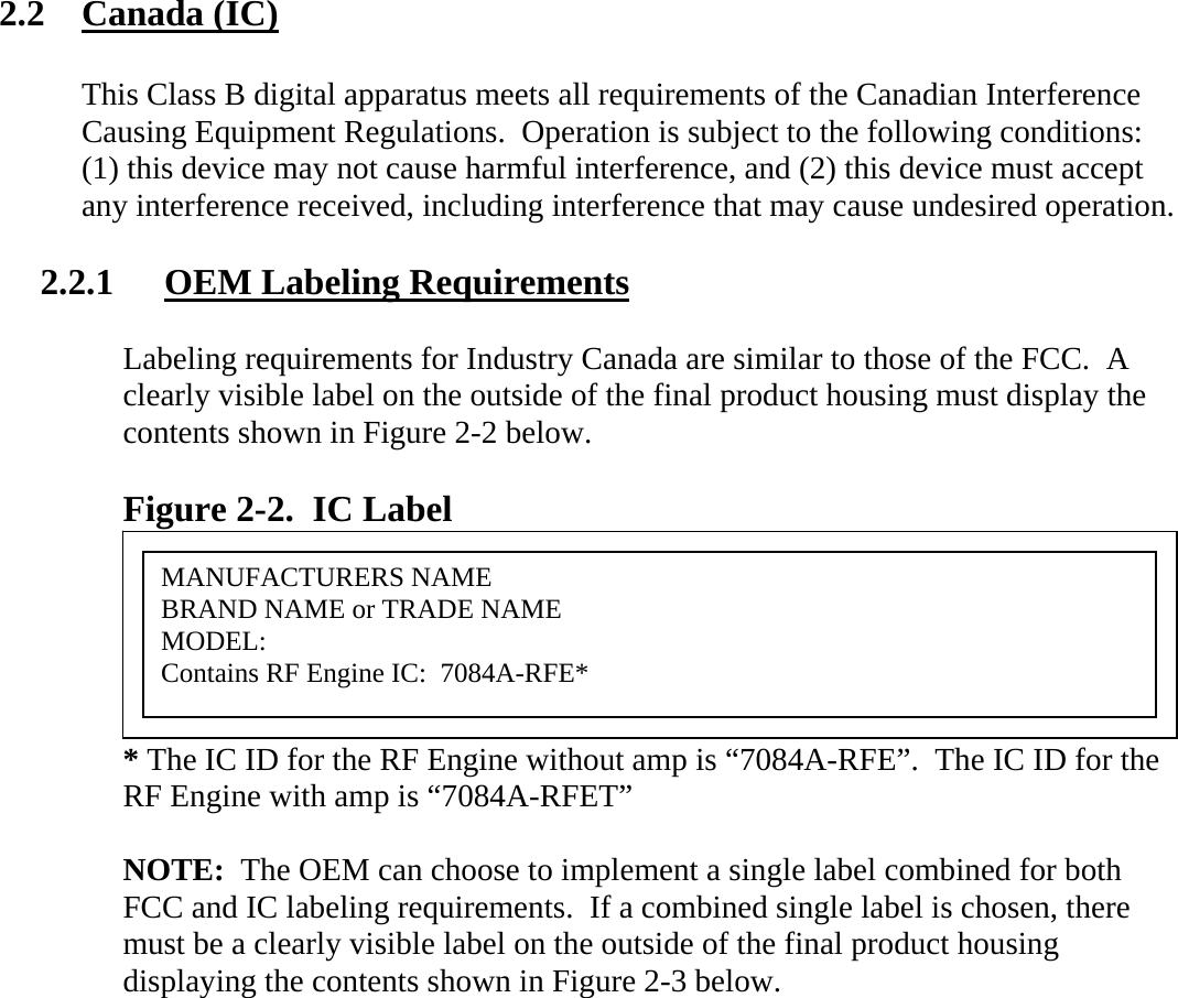
USERS MANUAL
Navigation menu
Upload a User Manual
Namespaces
Wiki Guide
HTML
PDF
Info
Views
User Manual
Discussion / Help
Navigation