Sysgration JRVCS1DC JRVCS1 Display Commander User Manual
Sysgration Ltd. JRVCS1 Display Commander User Manual
User_Manual

JRVCS1
RV CONTROL AND MONITORING SYSTEM
Installation and Operation Manual
JRVCS1
ii
CONTENTS
CONTENTS ................................................................................................................................. ii
Introduction .................................................................................................................................. 4
Thank You!............................................................................................................................ 4
Features................................................................................................................................ 4
Precautions ........................................................................................................................... 4
Packing List .......................................................................................................................... 4
Installation .................................................................................................................................... 5
Tools and Supplies................................................................................................................ 5
Disconnecting the Battery..................................................................................................... 5
Selecting the Mounting Location........................................................................................... 5
Mounting the Digital Commander (DC)................................................................................. 5
Wiring ........................................................................................................................................... 6
Troubleshooting ........................................................................................................................... 7
Specifications ............................................................................................................................... 9
FCC Notes..........................................................................................................................10
JRVCS1
iii
JRVCS1
4
INTRODUCTION
Thank You!
Thank you for choosing a Jensen product. We hope you will find the instructions in this owner’s
manual clear and easy to follow. If you take a few minutes to look through it, you’ll learn how to
use all the features of your new Jensen JRVCS1 for maximum enjoyment.
Features
Features of Jensen JRVCS1 system include:
Control four zones of lighting.
Monitor all water tank levels.
Control and monitor the Water Heater.
Control and monitor the Generator.
Precautions
Use the Proper Power Supply.
This product is designed to operate with a 12 volt DC, negative ground battery system (the
standard system in a North American vehicle).
Use Authorized Service Centers.
Do not attempt to disassemble or adjust this precision product; contact a professional for
assistance.
Avoid Moisture.
To reduce the risk of fire or electric shock, do not expose this equipment to rain or
moisture.
Avoid Cleaning Products.
The front of this unit should only be cleaned with a slightly damp cloth. Do not use
cleansers.
Use Recommended Accessories.
TO REDUCE THE RISK OF FIRE OR ELECTRIC SHOCK AND ANNOYING
INTERFERENCE, USE ONLY THE RECOMMENDED ACCESSORIES.
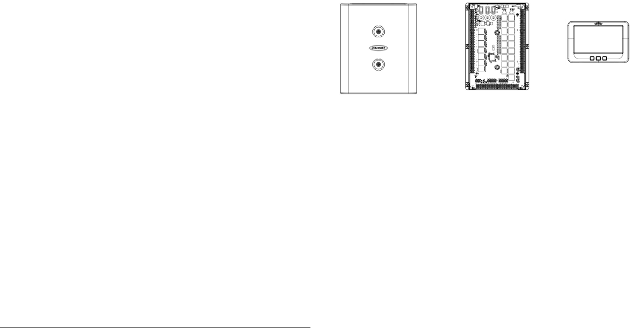
Packing List
1 Cover, 2 Thumb Screws 1 Body Control Module (BCM) 1 Display Commander (DC)
JRVCS1
5
INSTALLATION
It’s a good idea to read all of the instructions before beginning the installation. We recommend
having your Jensen JRVCS1 installed by a reputable RV dealership
Tools and Supplies
You will need these tools and supplies to install your JRVCS1:
Phillips screwdriver
Wire cutters and strippers
Electrical tape
Crimping tool
Volt meter/test light
Fork Crimp connectors
10 gauge wire for power and slide connections
14 and 18 gauge wire for all other connections
Four #8 PH (0.164” x 0.75”) screws for the DC
Six #8 PH (0.164” x 1.0”) screws for the BCM
Disconnecting the Battery
To prevent a short circuit, be sure to turn off 12V power and remove the negative (-) battery
cable prior to installation.
Selecting the Mounting Location
Select a mounting location, taking care to avoid the following:
Places exposed to heat-radiating appliances such as electric heaters
Adjacent to other equipment that radiates heat
Poorly-ventilated or dusty places
Moist or humid locations
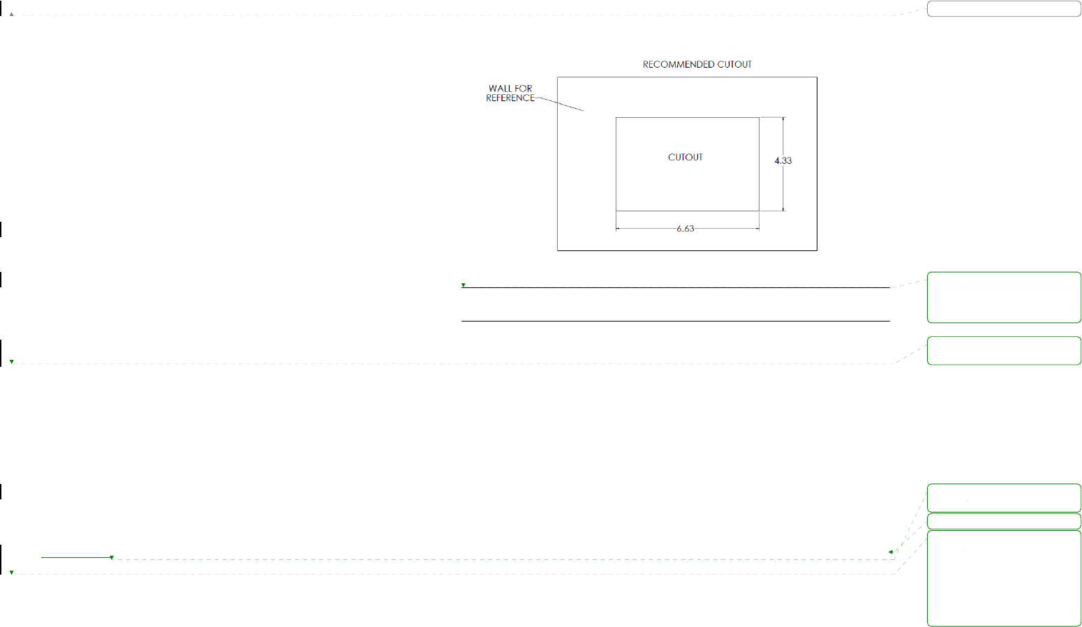
Mounting the Display Commander (DC)
Use the mounting hole diagram to measure and cut a mounting hole
Route power wires through the hole and connect
Check and ensure correct operation
Mount the unit using four #8 PH (0.164” x 0.75”) screws
Attach Trim ring
CUTOUT FOR DISPLAY COMMANDER (DC)
NOTE: Before cutting the mounting hole, make sure the area behind the mounting
location is clear of wires, fuel and vacuum or water lines.
格式化: 字型: 粗體
格式化: 左 0 字元
刪除:
刪除:
刪除:.
刪除:
JRVCS1
6
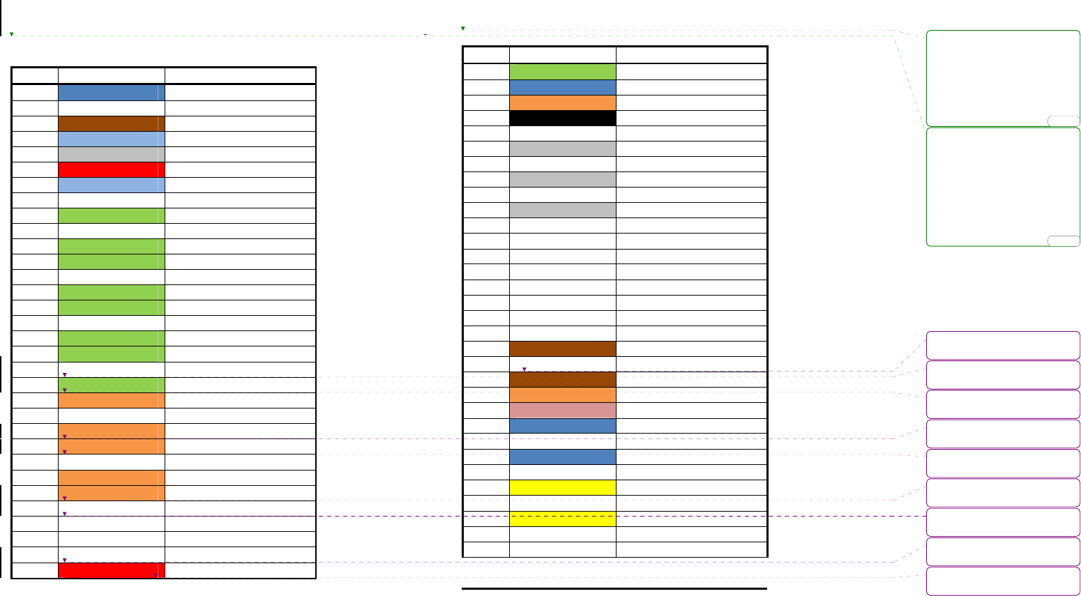
WIRING
The wiring diagram depicts all the wiring connections required for proper operation of the unit.
BODY CONTROL MODULE (BCM) CONNECTIONS
PIN NO.
WIRE COLOR/SIZE DESCRIPTION
1 BLUE (18) FRESH TANK 1 (IN)
2 FRESH TANK 2 (IN)
3 BROWN (18) BLACK TANK 1 (IN)
4 LIGHT BLUE (18) BLACK TANK 2 (IN)
5 GRAY (18) GRAY TANK 1 (IN)
6 RED (18) GRAY TANK 2 (IN)
7 LIGHT BLUE (18) GRAY TANK 3 (IN)
8 WHITE (18) TANK SENSOR GROUND (IN)
9 GREEN (14) LIGHT GROUP 1 + (IN)
10 WHITE (14) LIGHT GROUP 1 - (IN/OUT)
11 GREEN (14) LIGHT GROUP 1 + (OUT)
12 GREEN (14) LIGHT GROUP 2 + (IN)
13 WHITE (14) LIGHT GROUP 2 - (IN/OUT)
14 GREEN (14) LIGHT GROUP 2 + (OUT)
15 GREEN (14) LIGHT GROUP 3 + (IN)
16 WHITE (14) LIGHT GROUP 3 – (IN/OUT)
17 GREEN (14) LIGHT GROUP 3 + (OUT)
18 GREEN (14) LIGHT GROUP 4 + (IN)
19 WHITE (14) LIGHT GROUP 4 - (IN/OUT)
20 GREEN (14) LIGHT GROUP 4 + (OUT)
21 ORANGE (14) EXTERIOR LIGHTS + (IN)
22 WHITE (14) EXTERIOR LIGHTS - (IN/OUT)
23 ORANGE (14) EXTERIOR LIGHTS + (OUT)
24 ORANGE (14) SECURITY LIGHTS + (IN)
25 WHITE (14) SECURITY LIGHTS - (IN/OUT)
26 ORANGE (14) SECURITY LIGHTS + (OUT)
27 ORANGE (14) AWNING LIGHTS + (OUT)
28 WHITE (14) AWNING LIGHTS - (OUT)
29 AUX FUEL TANK + (IN)
30 AUX FUEL TANK - (OUT)
31 AUX TRIGGER 1 (OUT)
32 RED (18) GEN START +12V (OUT)
BODY CONTROL MODULE (BCM) CONNECTIONS
PIN NO. WIRE COLOR/SIZE DESCRIPTION
33 GREEN (18) GEN PRIME/STOP +12V (OUT)
34 BLUE (18) GEN SERVICE +12V (IN)
35 ORANGE (18) GEN HOUR METER +12V (IN)
36 BLACK (14) GEN FUEL TANK LEVEL (IN)
37 RED(14)/BROWN (18) GEN GROUND
38 GRAY (16) LANDING GEAR +12V (OUT)
39 WHITE (16) LANDING GEAR GROUND (OUT)
40 GRAY (16) HYDRAULIC VALVE EXTEND
41 WHITE (16) HYDRAULIC VALVE RETRACT
42 GRAY (16) HYDRAULIC VALVE +12V
43 WHITE (16) HYDRAULIC VALVE GROUND
44 AUX TRIGGER 2 (OUT)
45 AUX TRIGGER 3 (OUT)
46 AUX TRIGGER 4 (OUT)
47 AUX TRIGGER 5 (OUT)
48 AUX TRIGGER 6 (OUT)
49 AUX TRIGGER 7 (OUT)
50 AUX TRIGGER 8 (OUT)
51 BROWN (18) LOCKOUT SIGNAL +12V (IN)
52 WHITE (18) WATER HEATER GROUND
53 BROWN (18) WATER HEATER ON (GAS)
54 ORANGE (18) WATER HEATER ON (ELECTRIC)
55 PINK (18) WATER HEATER FAULT
56 BLUE (14) WATER PUMP +12V (OUT)
57 WHITE (14) WATER PUMP -12V (IN/OUT)
58 BLUE (14) WATER PUMP +12V (OUT)
59 WHITE (14) AWNING 2 -12V (OUT)
60 YELLOW (14) AWNING 2 +12V (OUT)
61 WHITE (14) AWNING 1 -12V (OUT)
62 YELLOW (14) AWNING 1 +12V (OUT)
63 (10) REAR JACKS (OUT)
64 (10) REAR JACKS (OUT)
刪除:
DETAIL A
刪除:
DETAIL A
刪除:
刪除:LIGHT
刪除:LIGHT
刪除:LIGHT
刪除:LIGHT
刪除:LIGHT
刪除:LIGHT
刪除:LIGHT
刪除:LIGHT
... [1]
... [2]
JRVCS1
7
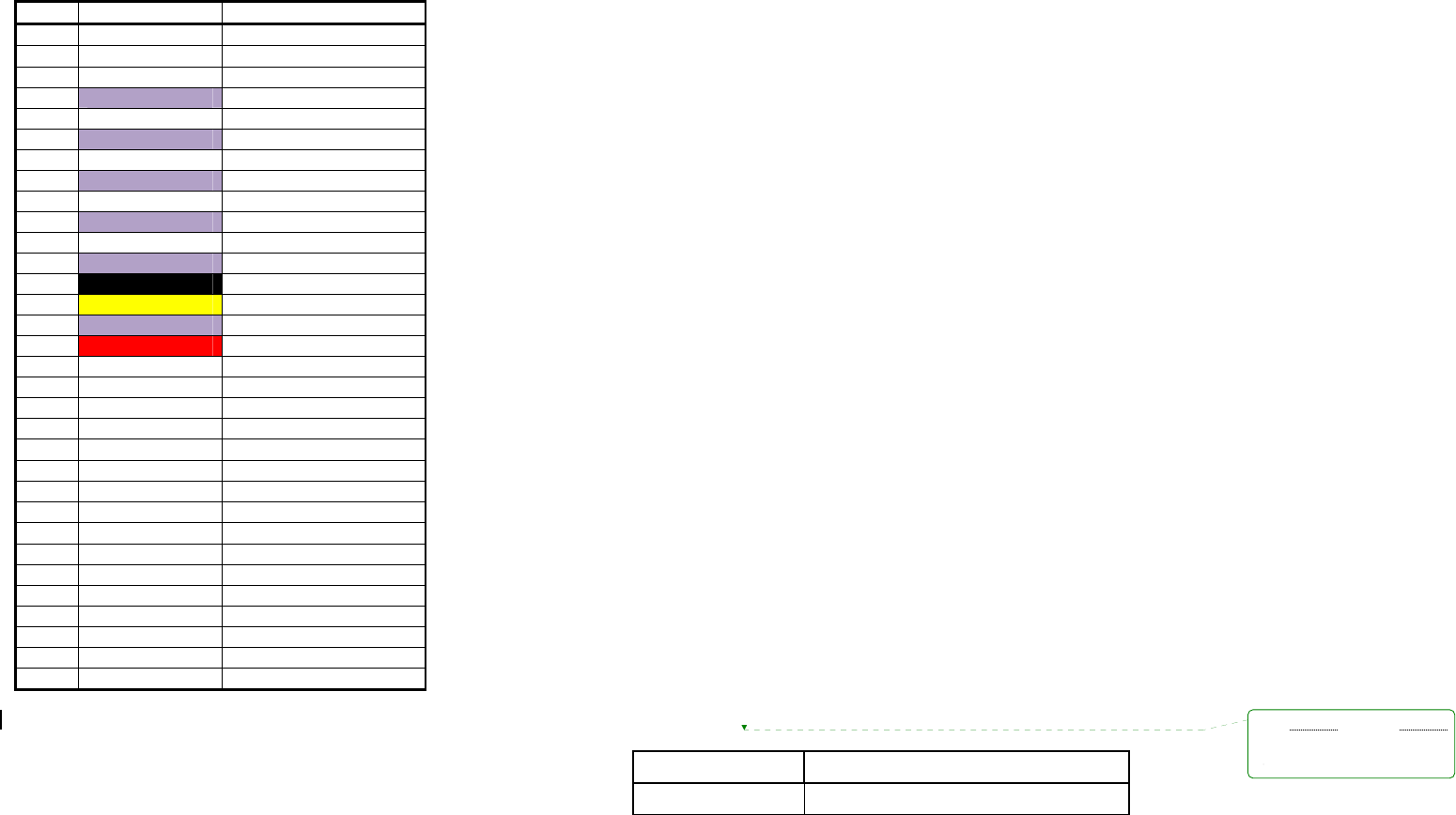
BODY CONTROL MODULE (BCM) CONNECTIONS
PIN NO.
WIRE COLOR/SIZE DESCRIPTION
65 (10) FRONT JACKS (OUT)
66 (10) FRONT JACKS (OUT)
67 WHITE (10) ELECTRIC SLIDE 5 -12V (OUT)
68 PURPLE (10) ELECTRIC SLIDE 5 +12V (OUT)
69 WHITE (10) ELECTRIC SLIDE 4 -12V (OUT)
70 PURPLE (10) ELECTRIC SLIDE 4 +12V (OUT)
71 WHITE (10) ELECTRIC SLIDE 3 -12V (OUT)
72 PURPLE (10) ELECTRIC SLIDE 3 +12V (OUT)
73 WHITE (10) ELECTRIC SLIDE 2 -12V (OUT)
74 PURPLE (10) ELECTRIC SLIDE 2 +12V (OUT)
75 WHITE (10) ELECTRIC SLIDE 1 -12V (OUT)
76 PURPLE (10) ELECTRIC SLIDE 1 +12V (OUT)
77 BLACK (10) CHASSIE GROUND (IN)
78 YELLOW (14) AWNING +12V (IN)
79 PURPLE (10) ELECTRIC SLIDE +12V (IN)
80 RED (10) BCM +12V (IN)
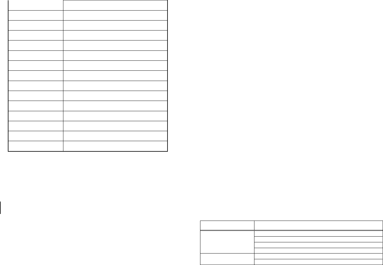
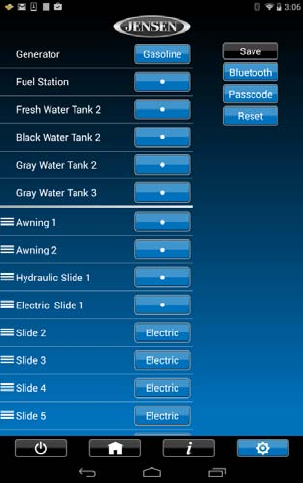
SETUP MENU LIST
ITEM SELECTION
GENERATOR
PROPANE OR GAS
刪除:分頁符號
JRVCS1
8
SLIDE 1 ELECTRIC OR HYDRAULIC
SLIDE 2 ELECTRIC OR HYDRAULIC
SLIDE 3 ELECTRIC OR HYDRAULIC
SLIDE 4 ELECTRIC OR HYDRAULIC
SLIDE 5 ELECTRIC OR HYDRAULIC
TRIGGER 1 MOMENTARY OR LATCH
TRIGGER 2 MOMENTARY OR LATCH
TRIGGER 3 MOMENTARY OR LATCH
TRIGGER 4 MOMENTARY OR LATCH
TRIGGER 5 MOMENTARY OR LATCH
TRIGGER 6 MOMENTARY OR LATCH
TRIGGER 7 MOMENTARY OR LATCH
TRIGGER 8 MOMENTARY OR LATCH
FRONT JACKS ELECTRIC OR HYDRAULIC
REAR JACKS ELECTRIC OR HYDRAULIC
TROUBLESHOOTING
Symptom Solution
Try the ON/OFF button.
Check main fuse in Distribution Panel.
Check 12V+ on wire to DC (RED wire).
DC will not turn ON or No
front panel operation
Check Ground wire to DC.
Check the Red power LED is off, No Power to the Body
Control Module (BCM) Check the fuse in the Distribution Panel.

JRVCS1
9
Check 12V+ on wire at pin 80.
Check Ground wire at pin 77.
SPECIFICATIONS
Display Commander (DC)
Operating Voltage . . . . . . . . . . . . . . . . . . . . . . . . . . . . . . . . . . . . . . . . . . . . . . . . . . . . . . . . 12vdc
Maximum Current Draw . . . . . . . . . . . . . . . . . . . . . . . . . . . . . . . . . . . . . . . . . . . . 600ma@12vdc
Minimum Operating Voltage . . . . . . . . . . . . . . . . . . . . . . . . . . . . . . . . . . . . . . . . . . . . . . …9vdc
Maximum Operating Voltage . . . . . . . . . . . . . . . . . . . . . . . . . . . . . . . . . . . . . . . . . . . . . . . .16vdc
Body Control Module (BCM)
Operating Voltage . . . . . . . . . . . . . . . . . . . . . . . . . . . . . . . . . . . . . . . . . . . . . . . . . . . . . . . . .12vdc
Maximum Current Draw . . . . . . . . . . . . . . . . . . . . . . . . . . . . . . . . . . . . . . . . . . . . . 600ma@12vdc
Minimum Operating Voltage . . . . . . . . . . . . . . . . . . . . . . . . . . . . . . . . . . . . . . . . . . . . . . . . . 9vdc
Maximum Operating Voltage . . . . . . . . . . . . . . . . . . . . . . . . . . . . . . . . . . . . . . . . . . . . . . . . 16vdc
JRVCS1 System
EPROM Non-Volatile Memory . . . . . . . . . . . . . . . . . . . . . . . . . . . . . . . . . . . . . . . . . . . . . . . . YES
Bluetooth Version . . . . . . . . . . . . . . . . . . . . . . . . . . . . . . . . . . . . . . . . . . . . . . . . . . . . . . . . 4.0 BLE
General

JRVCS1
10
Body Control Module . . . . . . . . . . . . . . . . . . . . . . . . . . . . . . . . 14.7” (W) x 17.87” (D) x 1.75” (H)
Display Commander . . . . . . . . . . . . . . . . . . . . . . . . . . . . . . . 195mm (W) x 132mm (D) x36.5mm
(H)
FCC Notes
WARNING! Changes or modifications to this unit not expressly approved by the party
responsible for compliance could void the user’s authority to operate the equipment.
NOTE: This equipment has been tested and found to comply with the limits for a Class B
digital device, pursuant to Part 15 of the FCC Rules. These limits are designed to
provide reasonable protection against harmful interference in a residential installation.
This equipment generates, uses and can radiate radio frequency energy and, if not installed
and used in accordance with the instructions, may cause harmful interference to radio
communications.
However, there is no guarantee that interference will not occur in a particular installation. If this
equipment does cause harmful interference to radio or television reception, which can be
determined by turning the equipment off and on, the user is encouraged to try to correct the
interference by one or more of the following measures:
Reorient or relocate the receiving antenna.
Increase the separation between the equipment and receiver.
Connect the equipment into an outlet on a circuit different from that to which the receiver is
connected.
Consult the dealer or an experienced radio/TV technician for help.
格式化: 置中
格式化: 靠右
刪除:1855mm
刪除:
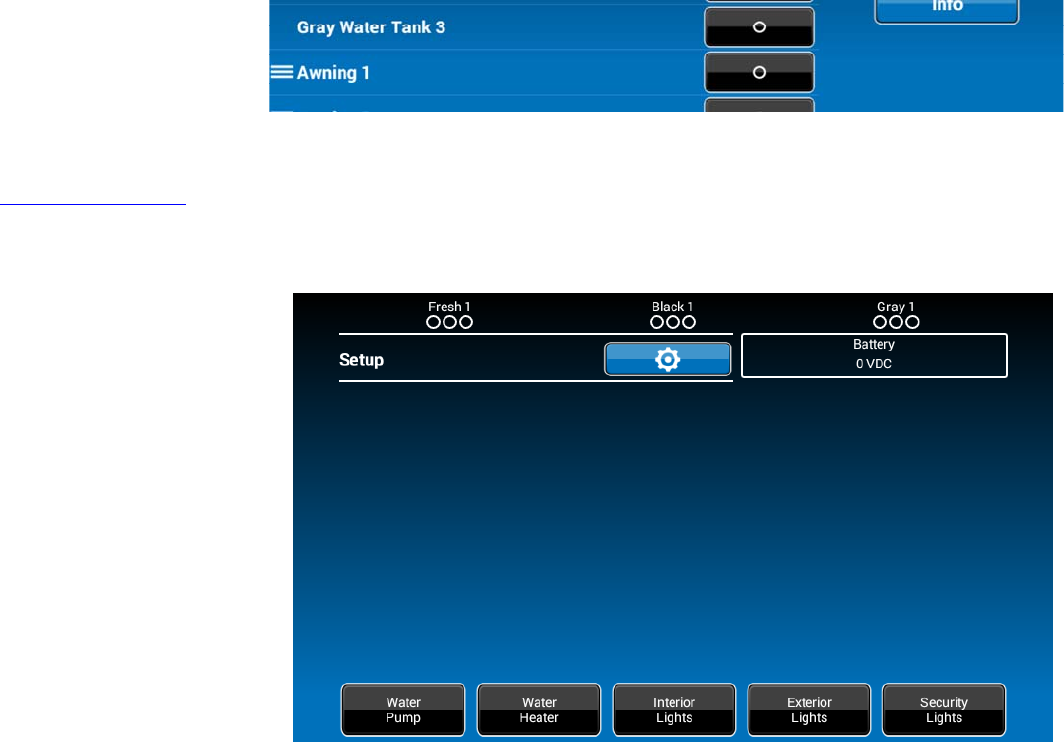
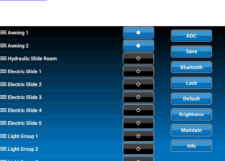
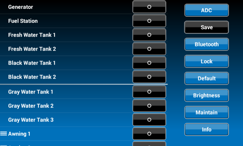
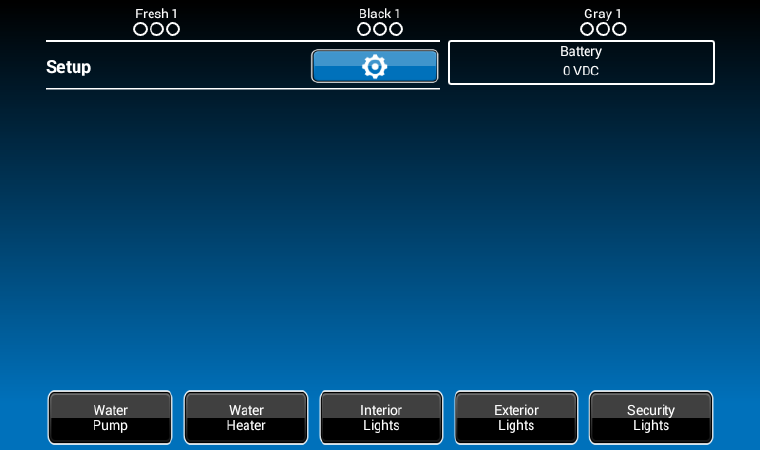
SETUPTextEditing
1.Select“setup”
2.Longpress“Awning1”

3.Adevicerenamewindowwillopen.Press“OK”aftercompletingthetextediting.

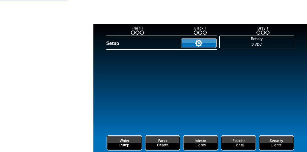
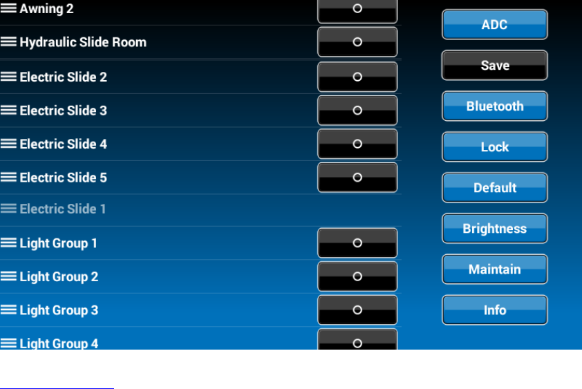
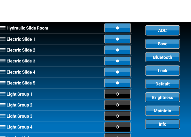
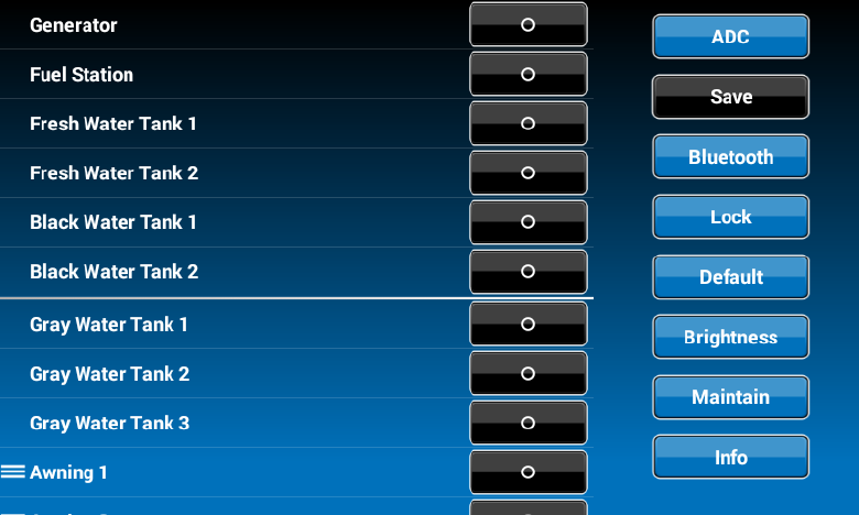
SETUPScrollListEditing
1.Select“setup”
2.Pressthe“Δiconbeforethedevicenameandmovethedevicetoanewlocation,“ElectricSlide1”asanexample.
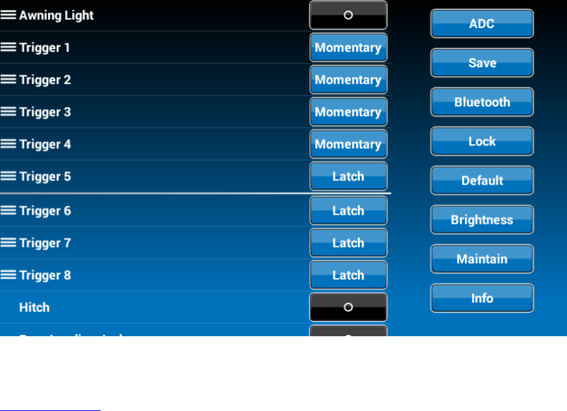
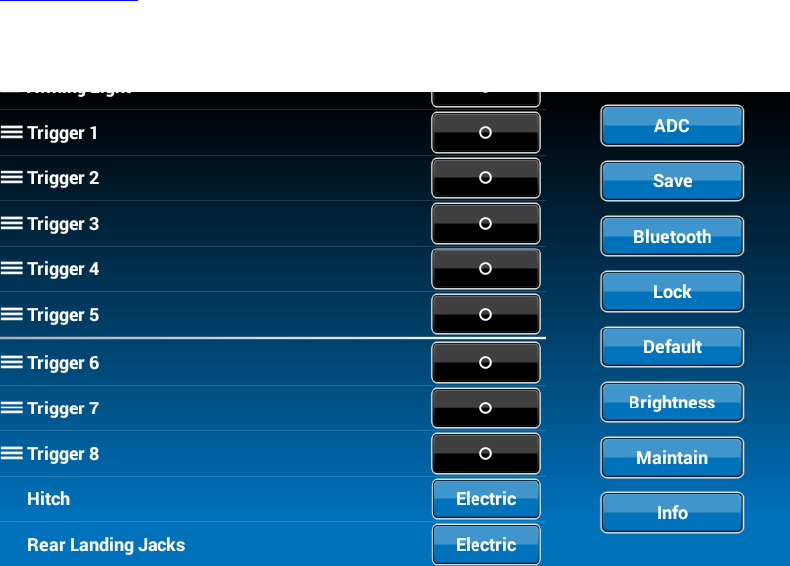
SETUPTriggers
1.Triggers1through8canbeaddedtothesystem.
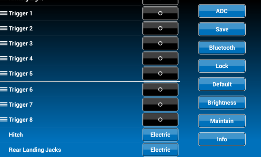
2Either“Momentary”or“Latch”canbeselectedforeachTrigger.
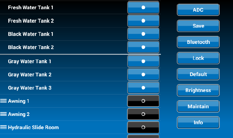
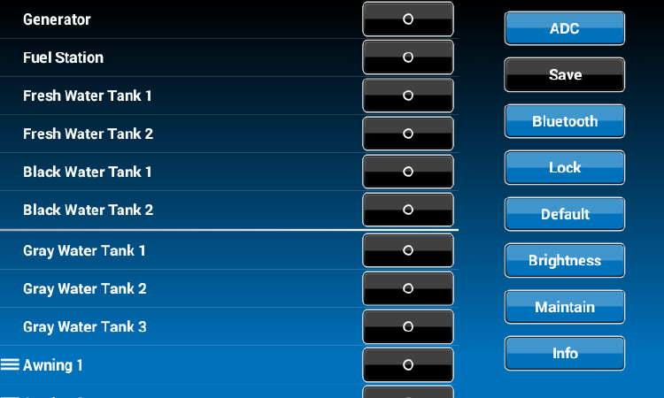
SETUPTanks
1.Freshwatertanks,BlackwatertanksandGraywatertankscanbeaddedtothesystem,
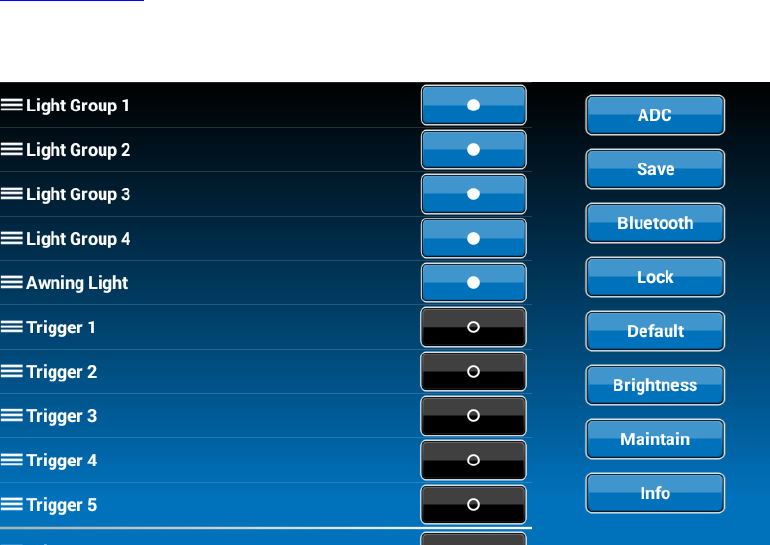
SETUPLights
1.LightGroupscanbeaddedtothesystem,
SETUPSlides
1.Slidescanbeaddedtothesystem,
SETUPAwnings
1.Awningscanbeaddedtothesystem,
SETUPJacks
1.Jackscanbeaddedtothesystem,

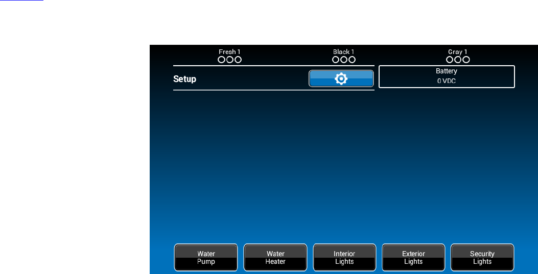
SETUPPasscode
1.Select“Setup”.
2.Press“Lock”toenterpasscodesetup.
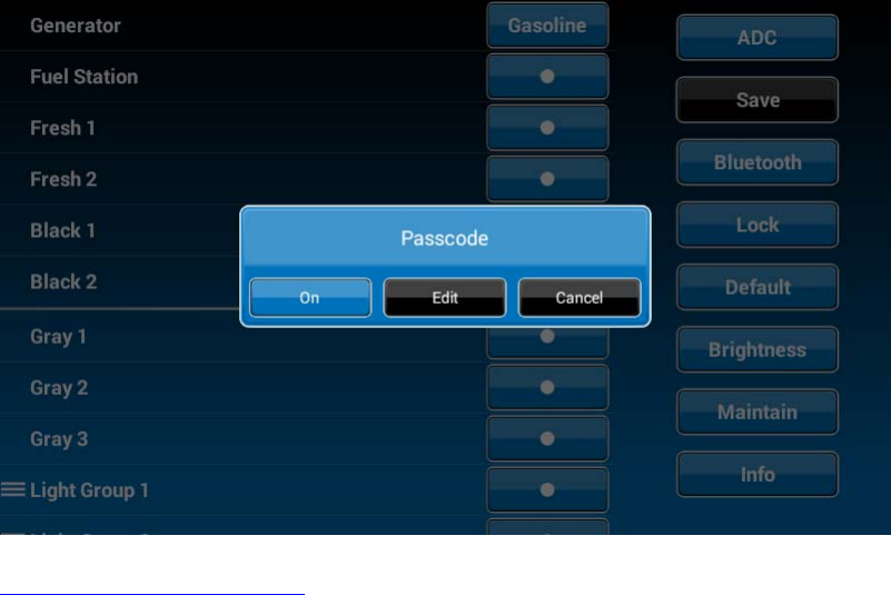
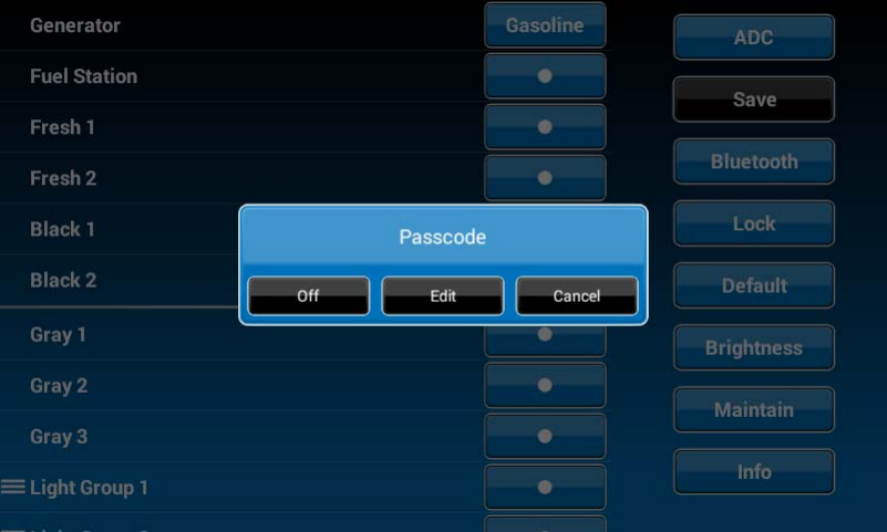
3.Thepasscodesetupwindowwillopen.(DEFAULTFACTORYSETTINGIS“ON”)
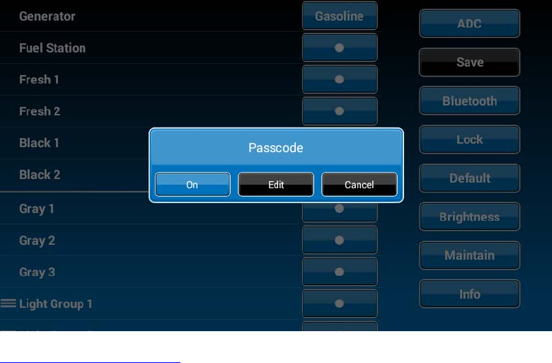
3.1TurnonPasscodeProtection
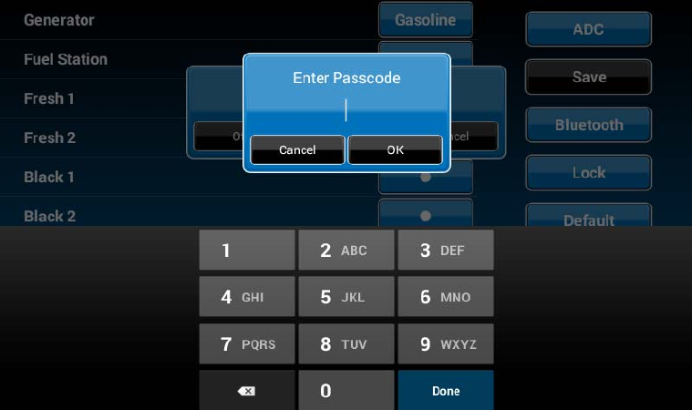
3.1.1.Press“On”toturnonpasscodeprotection.Thesystemwillrequestapasscode.(5391)
3.1.2.Selecttheidletimetoactivatethepasscodeprotection.
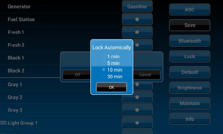
3.1.3Passcodeprotectionisactivated.
3.2TurnOFFPasscodeprotection
3.2.1.WhenpasscodeprotectionisON,press“On”buttontoturnoffpasscodeprotection
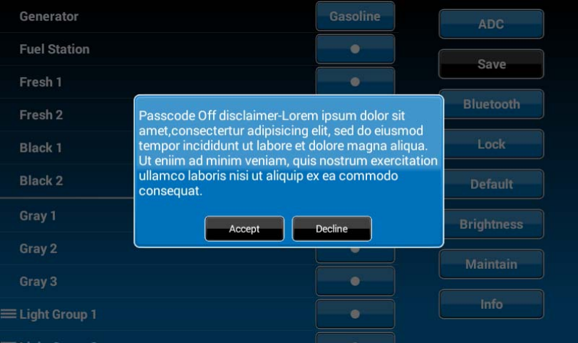
3.2.2.Readthepasscode”Off”disclaimerstatementandpress“Accept”toproceed.
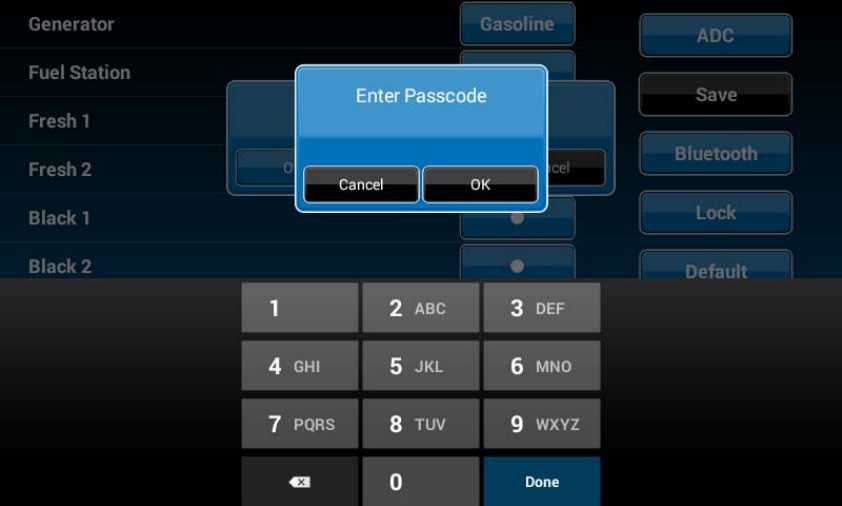
3.2.3Enterpasscodetoproceed
3.2.4.Passcodeprotectionisnowturnedoff.
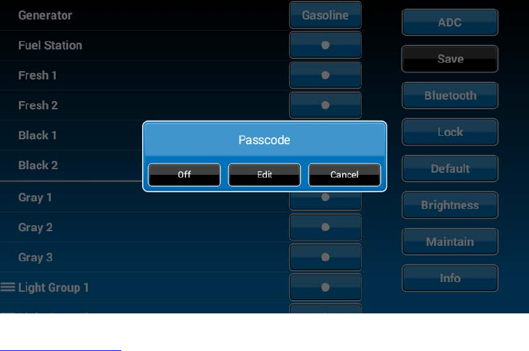
3.3ChangePasscode
3.3.1.Pressthe“Edit”buttontochangetoanewpasscode.
3.3.2.Entertheoldpasscode.
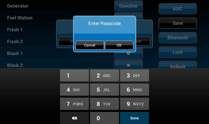
3.3.3.Enterthenewpasscode.
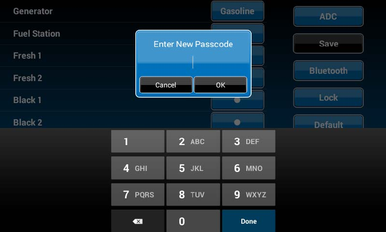
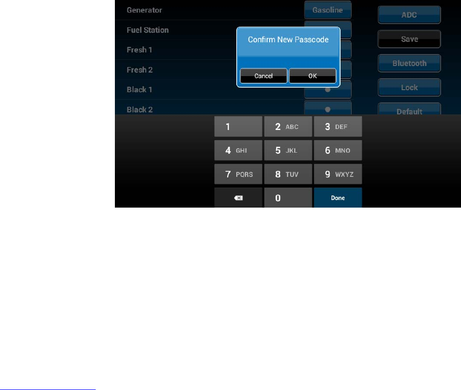
3.3.4.Confirmnewpasscode.
PAIRINGINSTRUCTIONS
DCtoBCM
1.Select“Setup”
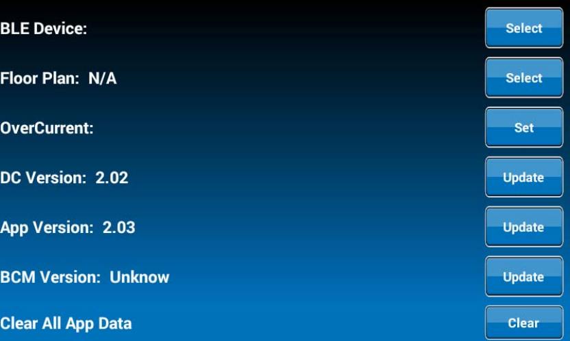
2.Select“Maintain”

3.Currently,itshowsnoBluetoothLowEnergydeviceconnectedtothisDC.Pressthe“Select”buttonacrossfromthe“BLEDevice”.
4.TheDCwillfindandlistallavailabledevices.
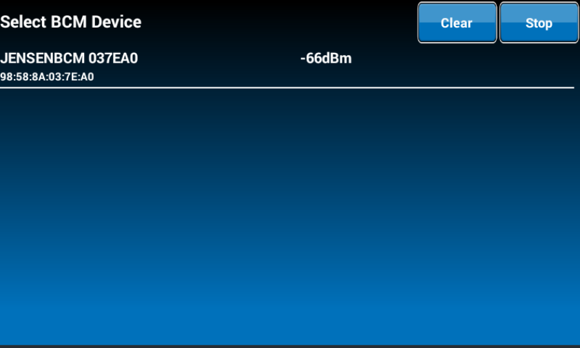
5.PressthetargetBCMtoconnect,“JENSENBCM037EA0”asanexample.
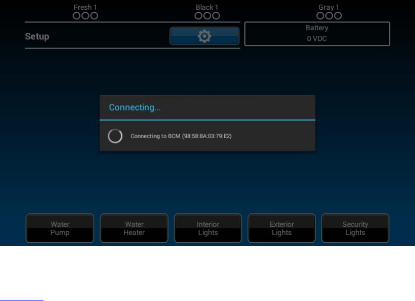
6.TheDCwillautomaticallyreturntothepreviouspageandshowthepairedBCM.

7.Pressthehotkeytoexitthe“Maintain”setuppageandtheDCwillstarttoconnecttotheselectedBCM.
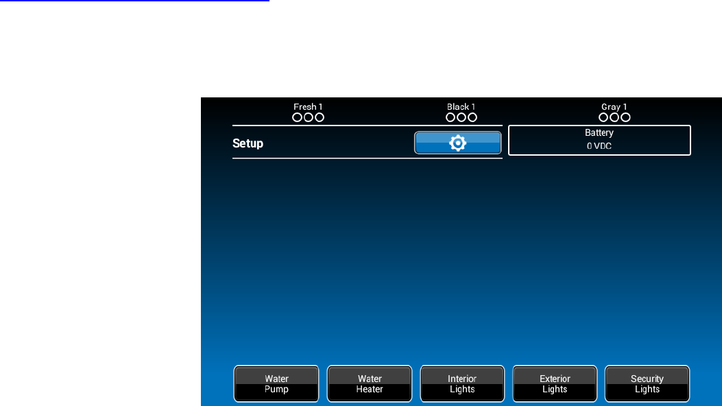
BCMtoDC
BLEconnectionisactivatedbytheDC.TheBCMonlyneedstopowerup.ThereisnoactionneededfromtheBCM.
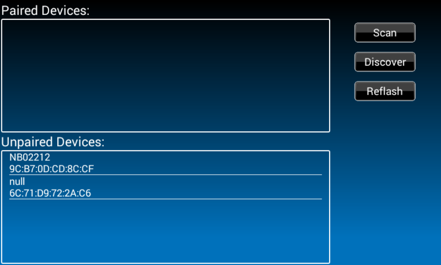
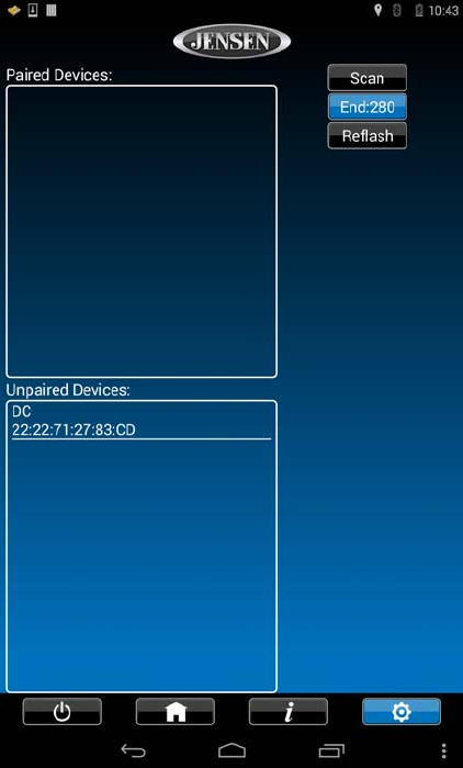
PAIRINGINSTRUCTIONSMobileDevicetoDC
1.DCside.
1.1Select“Setup”.
1.2.Select“Bluetooth”.
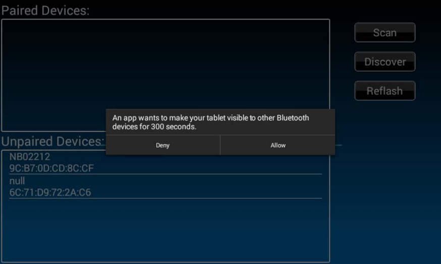
1.3.Currently,itshowsnoBTpaireddeviceconnectedtothisDC.Pressthe“Discover”buttontoactivatetheBTpairingmode.
1.4.Press“Allow”.
2.MobileDeviceside.
2.1Press“Bluetooth”onthe“Setup”pagetofindtheDCdevice.
2.2.TheMobileAPPwillscanfortheDCdevice.
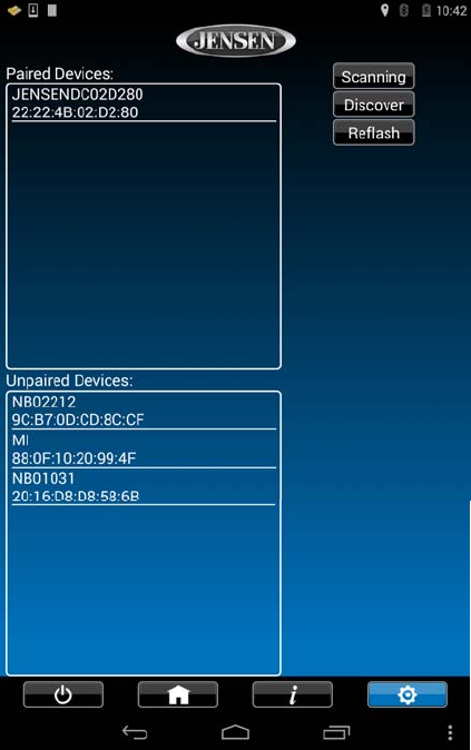
2.3.Findthe“DC”intheunpaireddevicelist.Press“DCdevice”topairwithit.
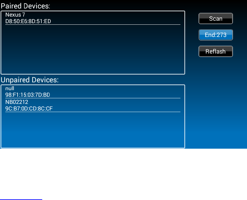
3.2TheDCnowshowstheMobiledeviceispaired.
SoftwareUpdate
1.Select“Setup”.
2.AttachtheupdatesoftwareUSBDrivebeforeselecting“Maintain”.

3.Thesystemwilllookforspecificfilenamesforsoftwareupdatesandturnon“Select”actionbuttonsaccordingly.
‐Filename:“JRVCS1_APVxxxx.apk”DCAPPupdate,(xxxxisversionnumber)
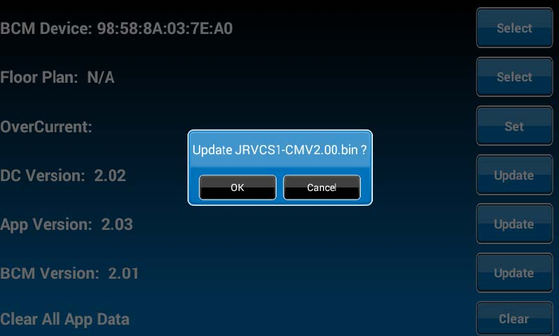
‐Filename:“JRVCS1_CMVxxxx.bin”BCMupdate,(xxxxisversionnumber)
‐Filename:“update.zip”DCAndroidOSupdate
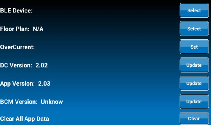
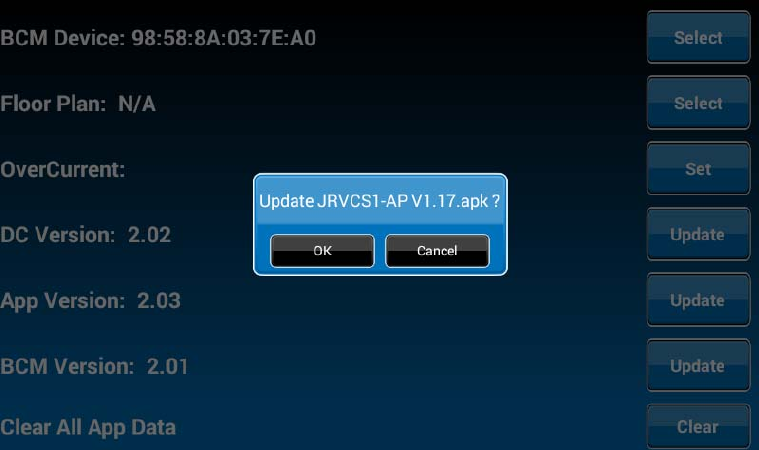
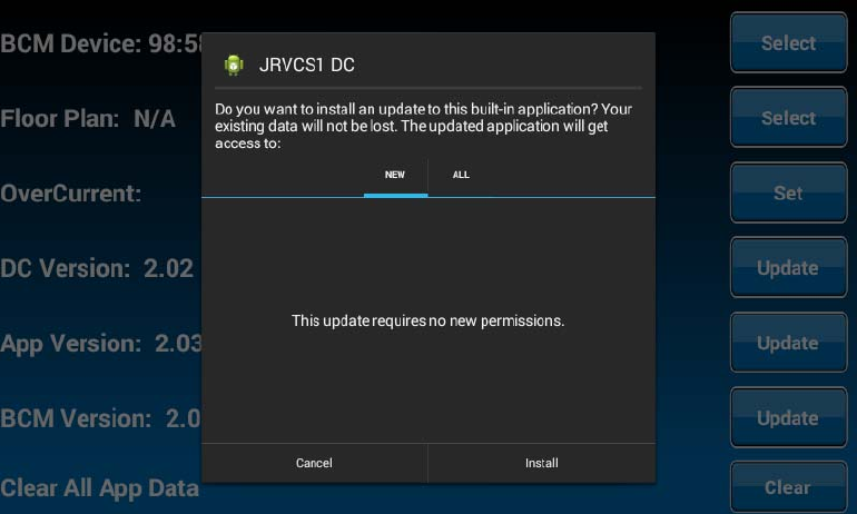
3.1.PresstheAPP“Update”buttontoupdateDCAPP.
3.2.PresstheBCM“Update”buttontoupdatetheBCMfirmware.
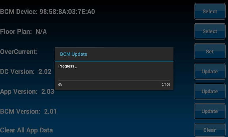
3.3PresstheDC“Update”buttontoupdateDCAndroidOS.


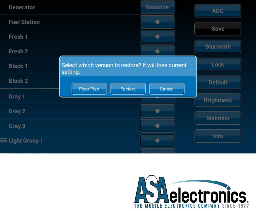
ResetFloorPlan
1.Select“Setup”.
2.Press“Default”torestorethesystemtoprevioussettings.
3.Select“FloorPlan”torestorethepreviousfloorplansetting.Currentsettingswillbelost.
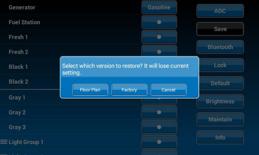
4.Select“Factory”torestorebacktoASAdefaultsettings.Currentsettingswillbelost.
ASA Electronics Corporation
www.asaelectronics.com
www.jensenrvdirect.com
©2015 ASA Electronics Corporation