Sysgration TA86 TPMS Receiver User Manual MeeBoss M100
Sysgration Ltd. TPMS Receiver MeeBoss M100
UserManual.wiki
>
Sysgration
>
TA86 User Manual
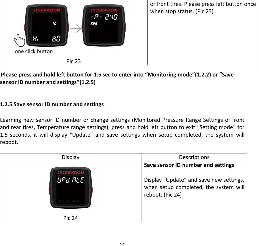
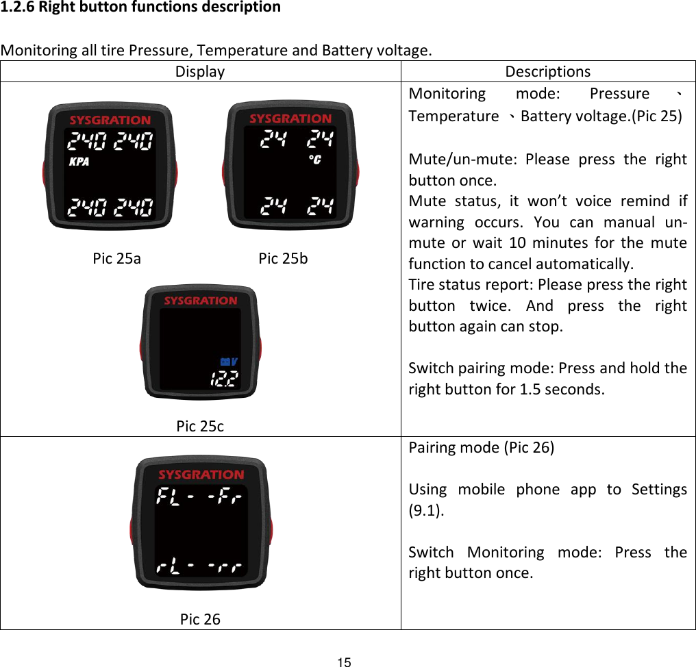
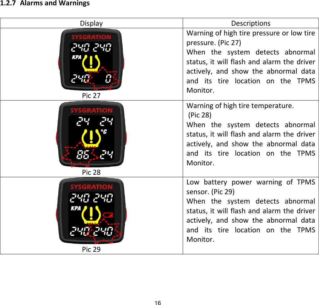
Users Manual
Navigation menu
Upload a User Manual
Namespaces
Wiki Guide
HTML
PDF
Info
Views
User Manual
Discussion / Help
Navigation