Sysgration TA86 TPMS Receiver User Manual MeeBoss M100
Sysgration Ltd. TPMS Receiver MeeBoss M100
Users Manual

1
TPMS Receiver
User Manual
Model: TA86

2
1. Product Introduction
With the new technology product: Bluetooth Low Energy Tire Pressure Monitoring System
Retrofit Kit (hereinafter referred to as BLE TPMS), the driver could get the accurate tire pressure
and temperature at any time through smart phone by using this kit while driving. When the system
detects abnormal status, it will alarm the driver actively, and show the abnormal data and its tire
location on the Multi Wheel Bluetooth TPMS APP (hereinafter referred to as APP).
2. Notice
FCC Notice
This device complies with Part 15 of the FCC Rules. Operation is subject to the following two conditions:
(1) This device may not cause harmful interference, and (2) This device must accept any interference
received, including interference that may cause undesired operation.
This equipment has been tested and found to comply with the limits for a Class B digital device, pursuant to
Part 15 of the FCC Rules. These limits are designed to provide reasonable protection against harmful
interference in a residential installation.
This equipment generates, uses and can radiate radio frequency energy and, if not installed and used in
accordance with the instructions, may cause harmful interference to radio communications. However, there
is no guarantee that interference will not occur in a particular installation. If this equipment does cause
harmful interference to radio or television reception, which can be determined by turning the equipment off
and on, the user is encouraged to try to correct the interference by one of the following measures:
. Reorient or relocate the receiving antenna.
. Increase the separation between the equipment and receiver.
. Connect the equipment into an outlet on a circuit different from that to which the receiver is connected.
. Consult the dealer or an experienced radio/TV technician for help.
3
FCC Caution: To assure continued compliance, any changes or modifications not expressly approved by
the party responsible for compliance could void the user's authority to operate this equipment. (Example -
use only shielded interface cables when connecting to computer or peripheral devices).
FCC Radiation Exposure Statement
This equipment complies with FCC RF radiation exposure limits set forth for an uncontrolled environment.
This equipment should be installed and operated with a minimum distance of 0.5 centimeters between the
radiator and your body.
This transmitter must not be co-located or operating in conjunction with any other antenna or transmitter.
The antennas used for this transmitter must be installed to provide a separation distance of at least 0.5 cm
from all persons and must not be co-located or operating in conjunction with any other antenna or
transmitter.

4
Specification
Operating Voltage
DC 12V/24V
Operating Humidity
90% MAX
Operating Temperature
-20℃ to 70℃
Storage Temperature
-25℃ to 85℃
Operating Current
0.25A@12V, 0.2A@24V
Sound Pressure (min.)
85dB@15cm
Battery voltage detector
DC 5V~32V, ±0.1V
Operating Frequency
2400MHz~2483.5MHz
Receiving sensitivity
< -85dBm
RF Transmitter Power
4dBm MAX
View angle
12 O’Clock
Weight
20g
5
1. Introduction of Smart Voice TPMS Monitor
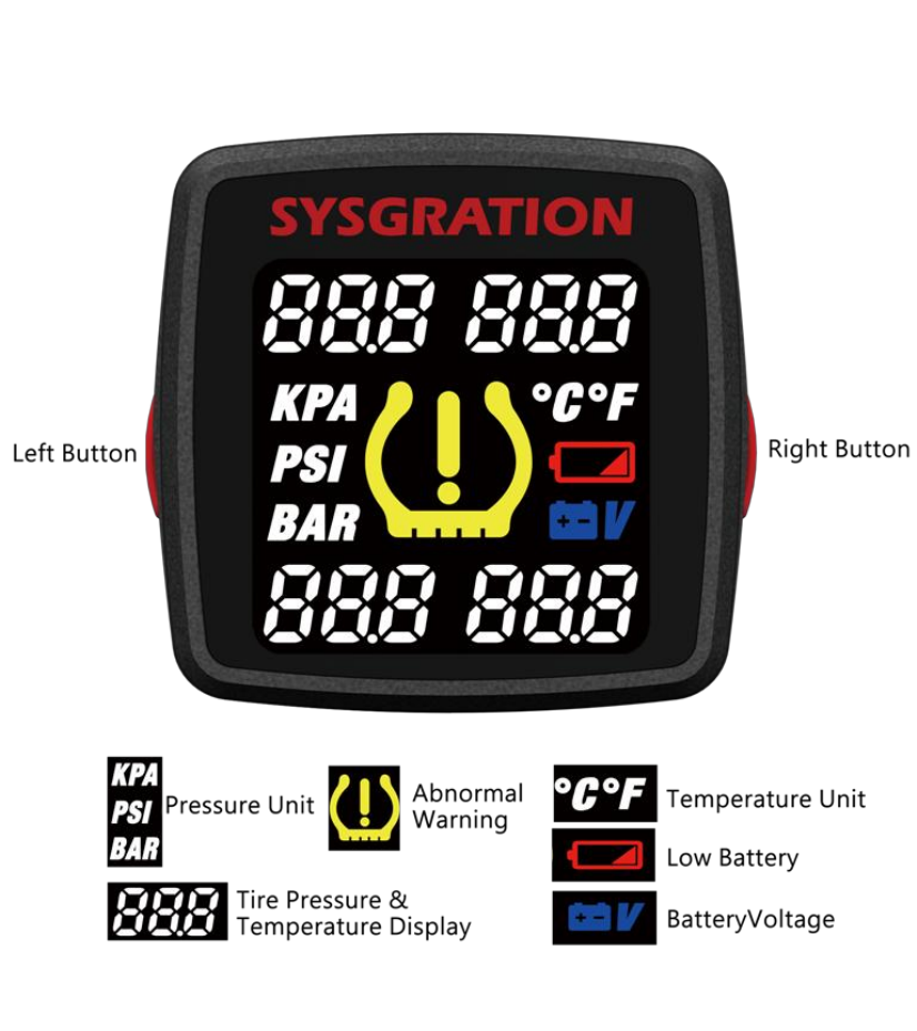
1.1 Product description
6
1.2 Function description
1.2.1 Initial setting
Display
Descriptions
Pic 1
Pic 2
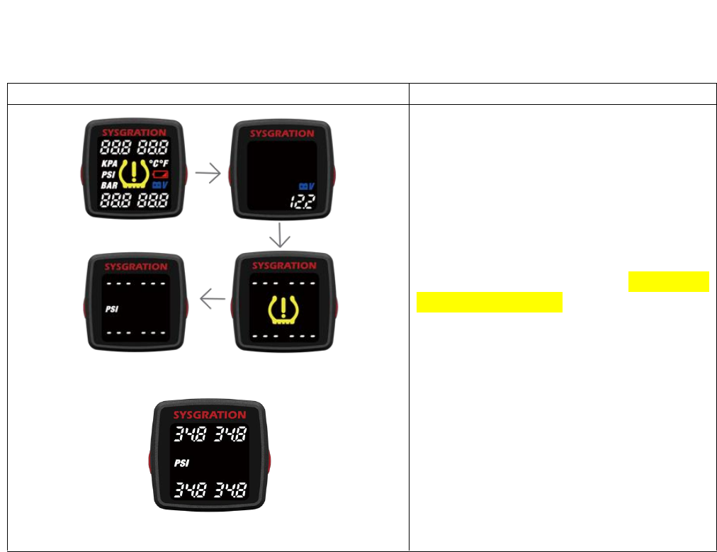
Initial setting (Pic 1)
1. When power on, display HOME page.
2. And display battery voltage.
3. And then display warning symbol, and
play welcome message.
4. Enter Monitoring mode, and receive
sensors signal.
5. Sensors setup completed. The factory
default for pressure unit is psi , after
receiving the normal, warning symbol will
disappear. (Pic2)
Note 1: Voice Monitor and TPMS Sensor
have been paired. If adjustments are
made in “ Settings”, please change the
settings in “ Voice Monitor”.(1.2.3-1.2.4)
7
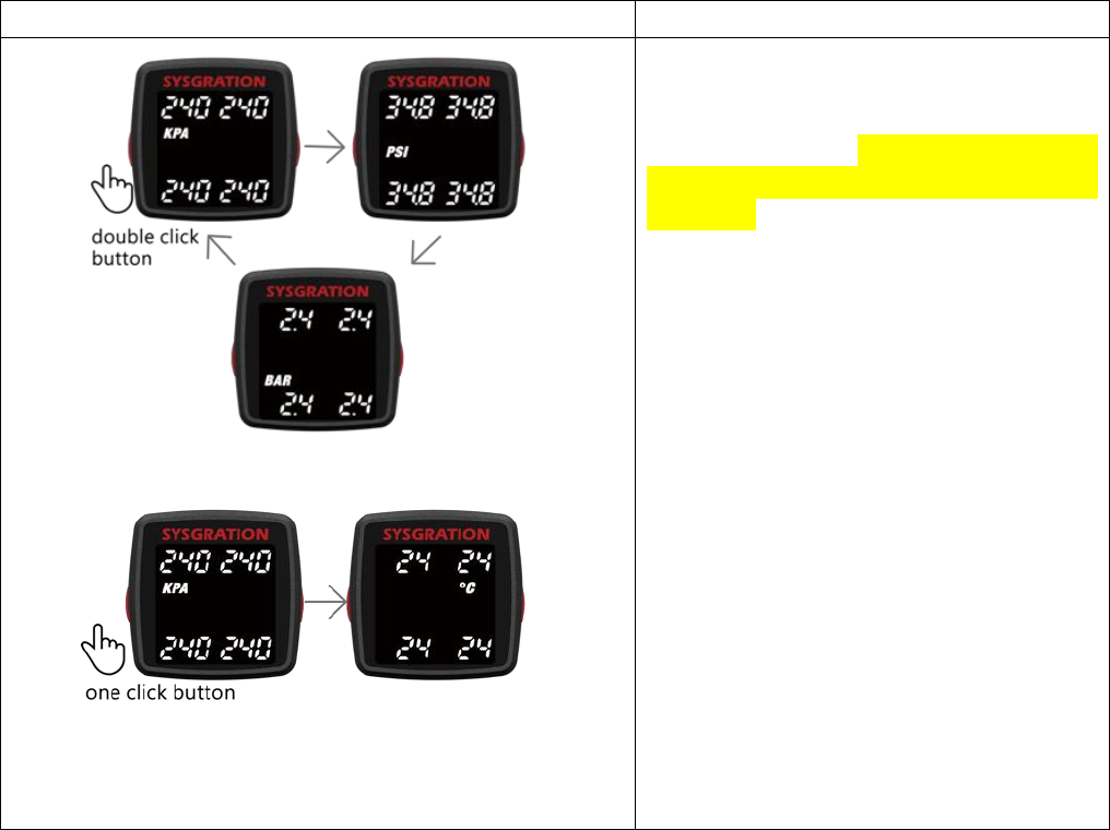
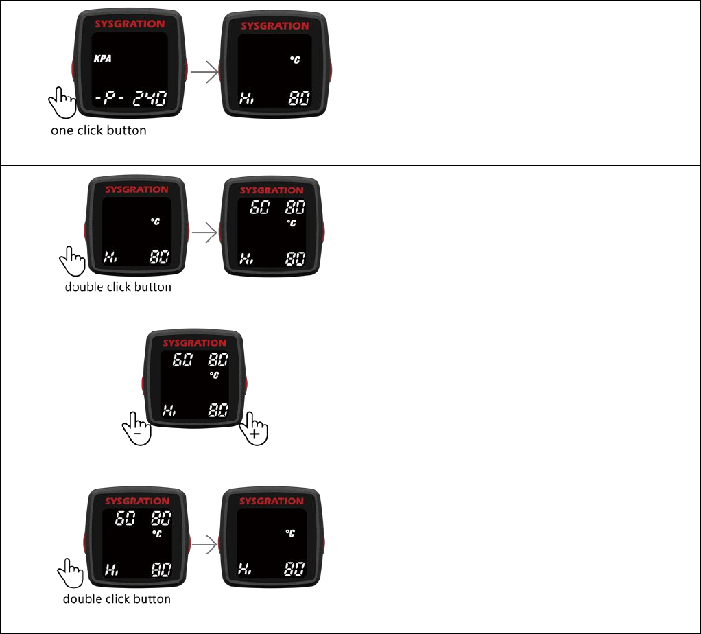
1.2.2 Monitoring Mode
“Monitoring mode” provide 3 kind of value: Pressure, Temperature and Battery Voltage.
Please press and hold the left button for 1.5 seconds to enter into “ID mode”.(1.2.3)
Display
Descriptions
Pic 3
Pic 4
Pressure data of sensors
Switch Pressure Unit : Please press the
left button twice. It displays 3 kinds of
pressure units, kPa, psi and bar in
sequence.(Pic 3)
Switch Temperature Unit : Please press
the left button once.(Pic 4)
8
Display
Descriptions
Pic 5
Pic 6
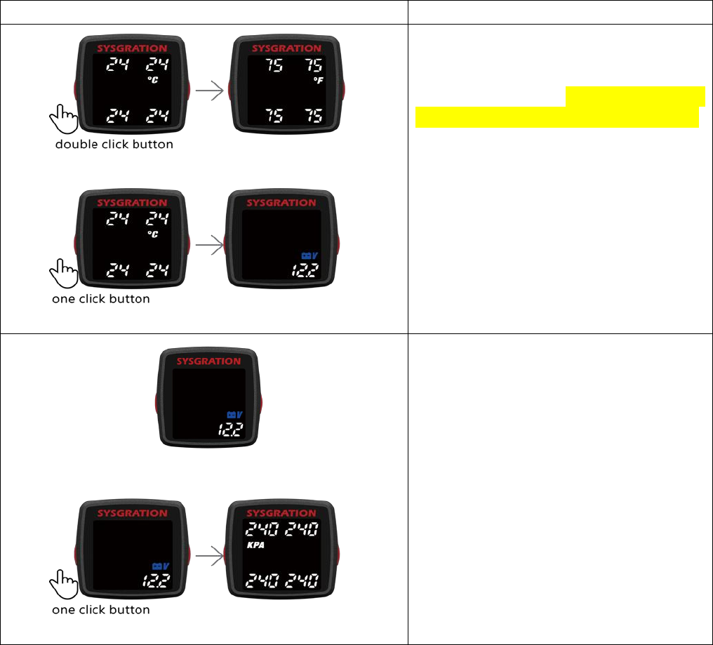
Temperature data of sensors
Switch Temperature Unit : Please press
the left button twice. It displays 2 kinds of
temperature units, °C and °F in sequence.
Switch Battery Voltage : Please press the
left button once.(Pic 6)
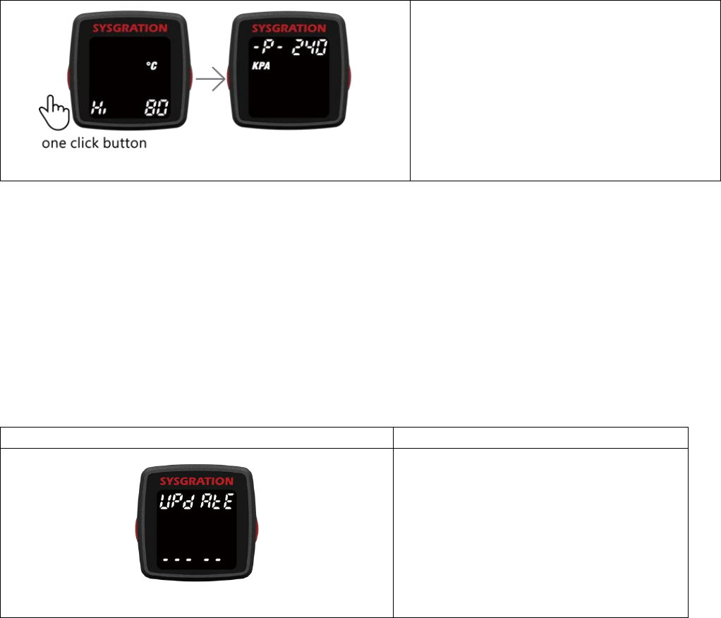
Pic 7
Pic 8
Battery Voltage
Display the voltage real time. (Pic 7)
Switch Pressure Unit : Please press the
left button once.(Pic 8)
9
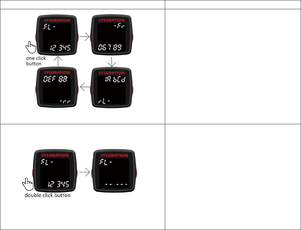
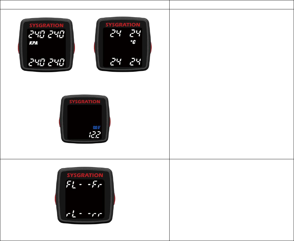
1.2.3 ID mode
Display each sensor ID number. Please press and hold the left button for 1.5 seconds to enter
into “Settings mode” .(1.2.4)
Display
Descriptions
Pic 9
Display sensor ID number
Switch tire Location: Please press the left
button once, the order of the tire location is
front-left (FL) → front-right(Fr) → rear-left
(rL) → rear-right(rr). (Pic 9)
Deflation Learning new sensor ID: Please
press the left button twice.
Pic 10
Learning new sensor ID number
Learning new sensor ID: Please press the
left button twice.
Choose front-left (FL) tire, sensor ID
number ”12345”, reset sensor ID number to
“-----“ and search new sensor ID number, to
deflation the tire need more than 15
seconds, It will look for the deflation signal,
showing new ID number on the display.(Pic
10)
10
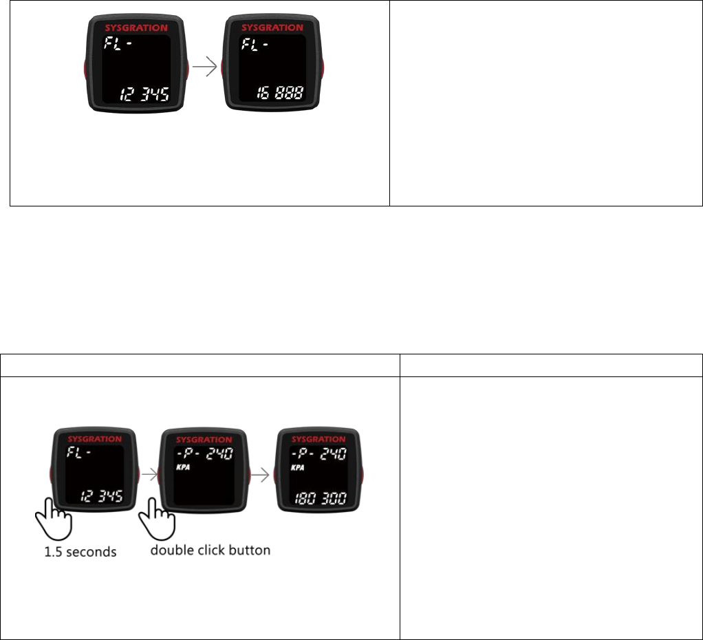
Pic 11
Deflation completed, display new ID
number “16888”.(Pic 11) Using the same
method, set up the ID number learning for
tires in sequence.
If learning fail, it will showing pervious ID
number”12345”
Stop learning: Please press the left button
once.
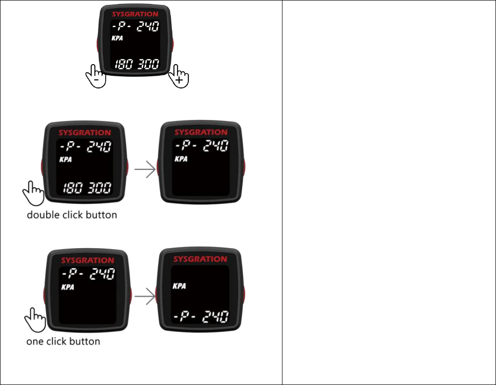
1.2.4 Settings mode
The product provide 3 kind of Monitored Settings : Monitored Pressure Range Settings of
front tires、Monitored Pressure Range Settings of rear tires and Temperature range. Please press
and hold the left button for 1.5 seconds to exit “Settings mode”, and back to “Monitoring mode”
(1.2.2) or saving new settings and reboot.(1.2.5)
Display
Descriptions
Pic 12
Monitored Pressure Range Settings of
front tires
Please press and hold the left button for
1.5 seconds. And press the left button
twice, it will display upper and lower
limits. (Pic.12)
11
Pic 13
Pic 14
Pic 15
Press the right button once to increase up
2.5kPa(0.36psi/0.1bar), and press the left
button once to reduce down 2.5kPa
(0.36psi/0.1bar) . (Pic 13)
Minimum Tire pressure : 10-250kPa (1.4-
36.2psi/0.1-2.5bar).
Maximum tire pressure: 280-640kPa (40.6-
92.8psi/2.8-6.4bar).
The factory default Minimum tire pressure
value is 180 kPa (26psi/1.8bar).
The factory default Maximum tire
pressure value is 300kPa (43psi/3bar).
Using the same method, set up the other
units in sequence.
Stop status: Please press the left button
twice again; it will just display default
value .(Pic 14)
Switch pressure range of rear tires: Please
press left button once when stop
status.(Pic 15)
Note : For the standard tire pressure
value, please refer to the placard located
at the side of the driver’s seat.
12
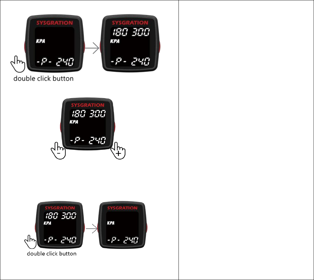
Pic 16
Pic 17
Pic 18
Monitored Pressure Range Settings of
rear tires
Please press and hold the left button for
1.5 seconds. And press the left button
twice, it will display upper and lower
limits. (Pic.16)
Press the right button once to increase up
2.5kPa(0.36psi/0.1bar), and press the left
button once to reduce down 2.5kPa
(0.36psi/0.1bar)(Pic 17) .
Minimum Tire pressure : 10-250kPa (1.4-
36.2psi/0.1-2.5bar).
Maximum tire pressure: 280-640kPa (40.6-
92.8psi/2.8-6.4bar).
Using the same method, set up the other
units in sequence.
The factory default Minimum tire pressure
value is 180 kPa (26psi/1.8bar).
The factory default Maximum tire
pressure value is 300kPa (43psi/3bar).
Stop status: Please press the left button
twice again; it will just display default
value. (Pic 18)
Switch temperature range : Please press
left button once when stop status.(Pic 19)
13
Pic 19
Note : For the standard tire pressure
value, please refer to the placard located
at the side of the driver’s seat.
Pic 20
Pic 21
Pic 22
Temperature range settings
Press the left button twice and showing
default range.(pic 20)
Press the right button once to increase up
1 °C (1.8 °F), and press the left button once
to reduce down 1 °C (1.8 °F) (Pic 21) .
Tire temperature range: 60~80 °C
(140~176 °F).
The factory default Maximum
Temperature value is 80°C / 176°F.
Stop status: Please press the left button
twice again; it will just display default
value. (Pic 22)
Switch Monitored Pressure Range Settings
14
Pic 23
of front tires. Please press left button once
when stop status. (Pic 23)
Please press and hold left button for 1.5 sec to enter into “Monitoring mode”(1.2.2) or “Save
sensor ID number and settings”(1.2.5)
1.2.5 Save sensor ID number and settings
Learning new sensor ID number or change settings (Monitored Pressure Range Settings of front
and rear tires, Temperature range settings), press and hold left button to exit “Setting mode” for
1.5 seconds, it will display “Update” and save settings when setup completed, the system will
reboot.
Display
Descriptions
Pic 24
Save sensor ID number and settings
Display “Update” and save new settings,
when setup completed, the system will
reboot. (Pic 24)
15
1.2.6 Right button functions description
Monitoring all tire Pressure, Temperature and Battery voltage.
Display
Descriptions
Pic 25a Pic 25b
Pic 25c
Monitoring mode: Pressure 、
Temperature 、Battery voltage.(Pic 25)
Mute/un-mute: Please press the right
button once.
Mute status, it won’t voice remind if
warning occurs. You can manual un-
mute or wait 10 minutes for the mute
function to cancel automatically.
Tire status report: Please press the right
button twice. And press the right
button again can stop.
Switch pairing mode: Press and hold the
right button for 1.5 seconds.
Pic 26
Pairing mode (Pic 26)
Using mobile phone app to Settings
(9.1).
Switch Monitoring mode: Press the
right button once.
16
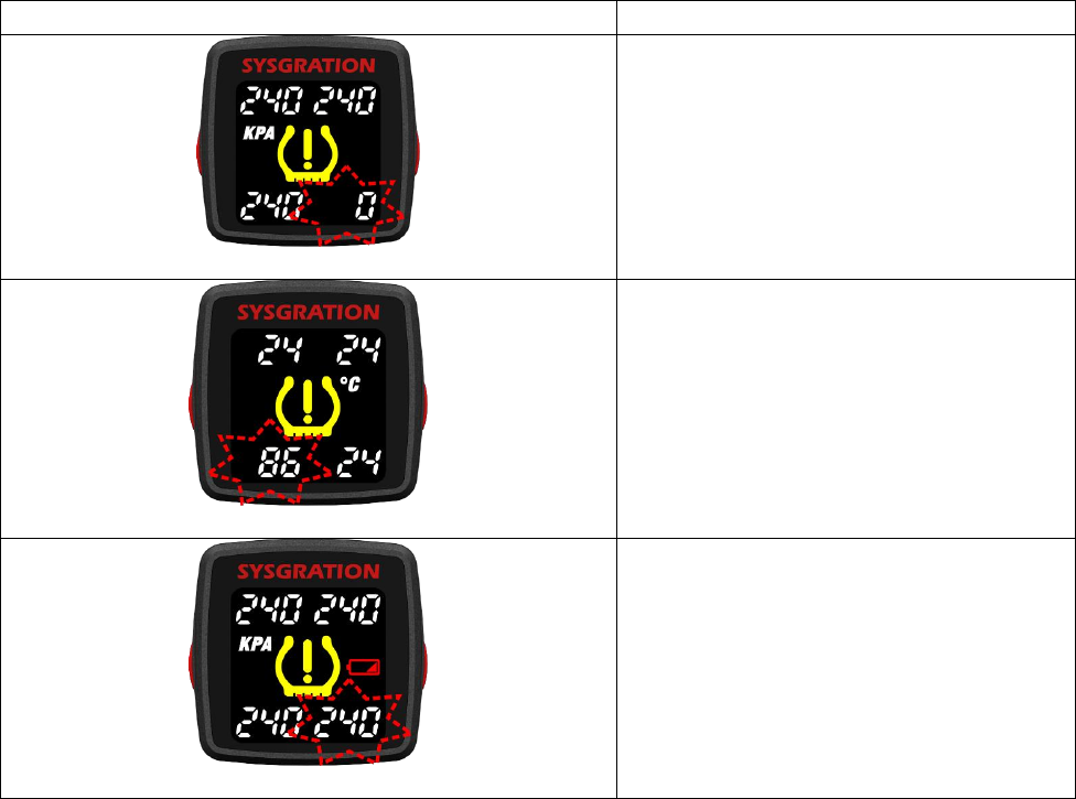
1.2.7 Alarms and Warnings
Display
Descriptions
Pic 27
Warning of high tire pressure or low tire
pressure. (Pic 27)
When the system detects abnormal
status, it will flash and alarm the driver
actively, and show the abnormal data
and its tire location on the TPMS
Monitor.
Pic 28
Warning of high tire temperature.
(Pic 28)
When the system detects abnormal
status, it will flash and alarm the driver
actively, and show the abnormal data
and its tire location on the TPMS
Monitor.
Pic 29
Low battery power warning of TPMS
sensor. (Pic 29)
When the system detects abnormal
status, it will flash and alarm the driver
actively, and show the abnormal data
and its tire location on the TPMS
Monitor.

17
Warranty Policy
Thank you for buying this product and giving us support. From the date of purchase, we
provide a one-year warranty for the product, protecting the client’s interest by providing product
quality assurance. During the warranty period, under normal operation and in the event of a
faulty product, the company is willing to repair the faulty product or have it replaced, enabling
you to get the guarantee and demonstrating the company’s responsible attitude toward products.
But the product warranty must meet the following conditions:
1. Defective products need to be provided to local dealer to confirm purchase date and cause of
defect.
2. Products must be operated correctly, as indicated in the user manual.
3. Product has not been disassembled by yourself.
4. The main cause of product failure is due to manufacture issues.
Disclaimer:
This product is only to be used as precautionary warning and provides to user as a convenient
secondary safety equipment. Please follow the standard installation procedures or ask a qualified
tire shop to install the product. If the tire has been damaged or traffic accident resulting from
improper driving behavior occurs, the company will not be responsible for any civil or criminal
liabilities.
Other relevant latest information of SYSGRATION TPMS is available at our website
(http://www.sysgration.com/ ) and our Facebook Page (http://www.facebook.com/sysgration) for
latest information.
2016G06a