System Sensor 2151 Users Manual
2151 to the manual 7df93305-a70e-4c46-aeb2-15604cdc538e
2015-02-02
: System-Sensor System-Sensor-2151-Users-Manual-490716 system-sensor-2151-users-manual-490716 system-sensor pdf
Open the PDF directly: View PDF ![]() .
.
Page Count: 4
D100-04-00 1 I56-581-07R
2151 Low Profile
Photoelectronic Plug-in
Smoke Detector
INSTALLATION AND MAINTENANCE INSTRUCTIONS
3825 Ohio Avenue, St. Charles, Illinois 60174
1-800-SENSOR2, FAX: 630-377-6495
www.systemsensor.com
Before Installing
Please thoroughly read the System Sensor manual A05-
1003, Applications Guide for System Smoke Detectors,
which provides detailed information on detector spacing,
placement, zoning, wiring, and special applications. Copies
of this manual are available from System Sensor.
NOTICE: This manual should be left with the owner/user
of this equipment.
IMPORTANT: The detector used with this base must be
tested and maintained regularly following NFPA 72 require-
ments. The detector used with this base should be cleaned
at least once a year.
General Description
The 2151 low-profile photoelectronic detector uses a state-
of-the-art optical sensing chamber. This detector is designed
to provide open area protection and to be used with com-
patible UL listed control panels only. The capability of plug-
ging this detector into a variety of special bases makes it
more versatile than equivalent direct-wired models.
Two LEDs on each detector provide local 360° visible
alarm indication. They flash every ten seconds indicating
that power is applied and the detector is working properly.
The LEDs latch on in alarm. Remote LED annunciator
capability is standard and may be implemented through
an optional accessory RA400Z. The alarm can be reset
only by a momentary power interruption. This detector
may be tested by activating the internal reed switch with
a magnet.
Base Selection And Wiring Guide
Refer to the installation instructions for the Plug-in
Detector Bases for base selection and wiring instructions.
System Sensor has a variety of detector bases available for
Specifications
Size
Height: 1.7 inches (43 mm)
Diameter: 4.0 inches (101 mm)
Weight: 3.6 oz. (102 g)
Operating Temperature Range: 0°C to 49°C (32°F to 120°F)
Operating Humidity Range: 10% to 93% Relative Humidity noncondensing
Latching Alarm: Reset by momentary power interruption.
this smoke detector, including 2-wire applications with and
without relays and/or current limiting resistors, 4-wire and
120VAC applications.
All bases are provided with screw terminals for power,
ground, remote annunciator connections and relay contact
connections, if applicable. The electrical ratings for each
detector-base combination are also included in the base
installation instructions.
Installation
NOTE: All wiring must conform to applicable local codes,
ordinances, and regulations.
NOTE: Verify that all detector bases are installed, that
the initiating-device circuits have been tested, and
that the wiring is correct. (Refer to detector base
manual for testing procedure.)
WARNING
Remove power from initiating-device circuits before install-
ing detectors.
1. Install detectors:
a. Place the detector into the detector base.
b. Turn the detector clockwise until the detector drops
into place.
c. Continue turning detector clockwise to lock it in
place.
2. Tamper Resistance: The detector bases can be made tam-
per resistant. When capability is enabled, detectors can-
not be removed from the base without the use of a tool.
See the detector base installation manual of the detector
base for details in using this capability.
3. After all detectors have been installed, apply power to
the control unit.
D100-04-00 2 I56-581-07R
4. Test the detector using the magnet as described under
TESTING.
5. Reset the detector at the system control panel.
6. Notify the proper authorities that the system is back on
line.
CAUTION
Dust covers are an effective way to limit the entry of dust
into smoke detector sensing chambers. However, they may
not completely prevent airborne dust particles from enter-
ing the detector. Therefore, System Sensor recommends the
removal of detectors before beginning construction or other
dust producing activity.
Be sure to remove the dust covers from any sensors that
were left in place during construction as part of returning
the system to service.
CAUTION
Smoke detectors are not to be used with detector guards
unless the combination has been evaluated and found
suitable for that purpose.
Testing
Before testing, notify the proper authorities that the smoke
detector system is undergoing maintenance and will tem-
porarily be out of service. Disable the zone or system
undergoing maintenance to prevent unwanted alarms.
Detectors must be tested after installation and as part of
periodic maintenance. Test the 2151 as follows:
NOTE: Before testing the detector, check to ensure the
LEDs blink. If they do not, the detector has lost
power (check the wiring) or it is defective (return
it for repair).
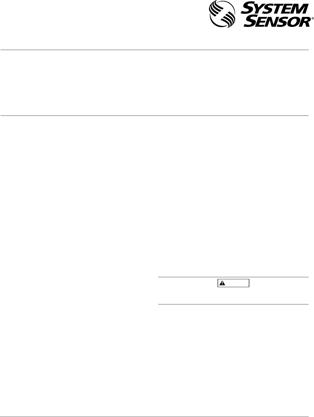
LED
LED
T
EST MODULE
SOCKET
TEST
MAGNET
PAINTED
SURFACE
Figure 1. Bottom and side views showing position of test magnet:
A. Test Magnet (p/n M02-04-01 or M02-09-00)
1. Place the magnet against the cover in the location
designated by the raised mark to activate the test fea-
ture (see Figure 1).
2. The LEDs should latch ON within 5 seconds indicat-
ing alarm and annunciating the panel.
B. Test Module ( MOD400R)
Use the MOD400R with a DMM or voltmeter to check
the detector sensitivity as described in the MOD400R
manual.
C. Aerosol Generator (Gemini 501)
Set the generator to represent 4% to 5%/ft. obscuration
as described in the Gemini 501 Manual. Using the bowl-
shaped applicator, apply aerosol until unit alarms.
Notify the proper authorities that the system is back on
line.
Detectors that fail these tests should be cleaned as described
under MAINTENANCE and retested. If the detectors still
fail these tests, they should be returned for repair.
Maintenance
It is recommended that the detector be removed from
its mounting base to facilitate cleaning. The detector is
cleaned as follows:
NOTE: Before removing the detector, notify the proper
authorities that the smoke detector system is
undergoing maintenance and will be temporarily
out of service. Disable the zone or system undergo-
ing maintenance to prevent unwanted alarms.
C0627-00
D100-04-00 3 I56-581-07R
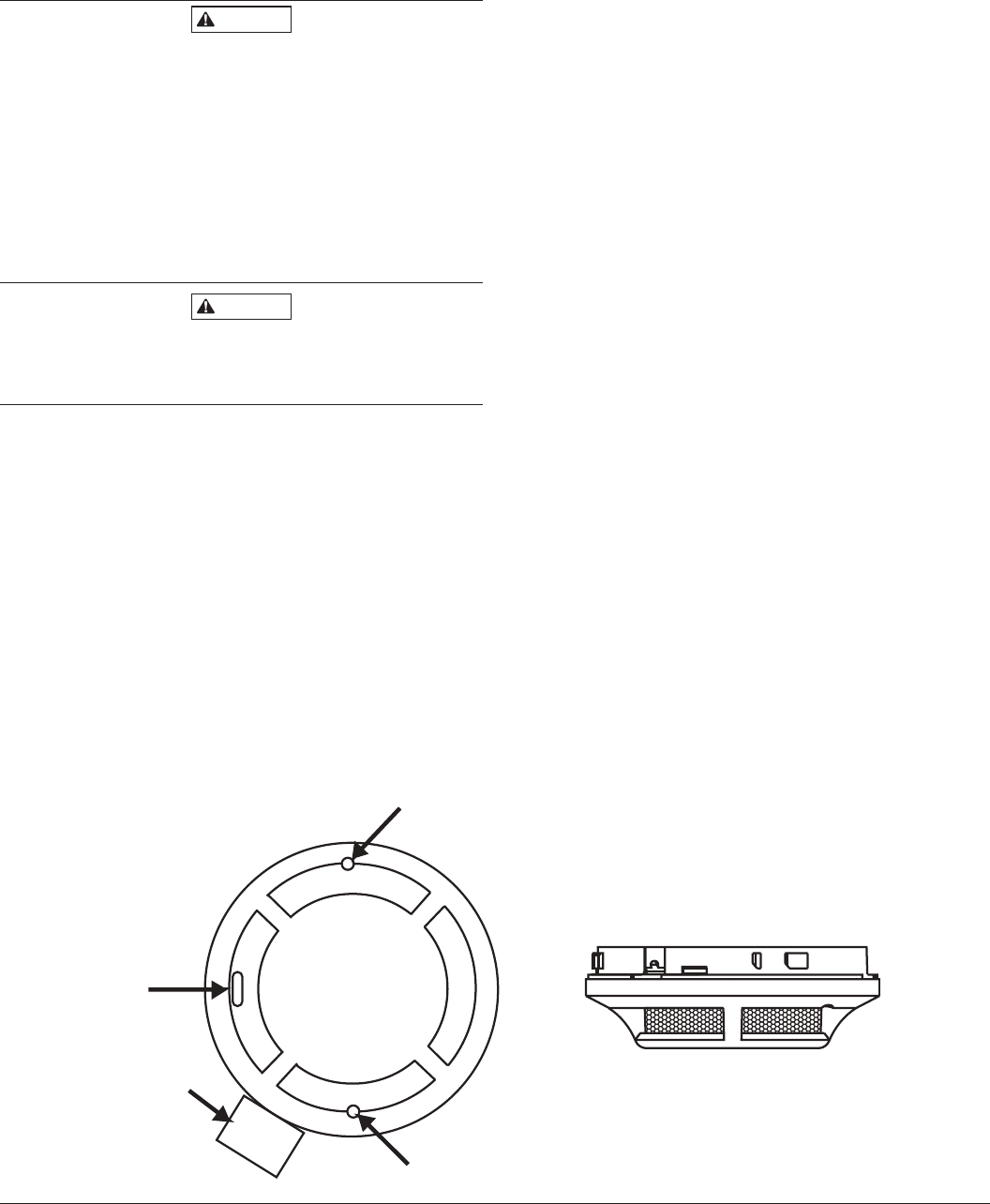
SENSING
CHAMBER
SENSING
CHAMBER
COVER
SENSOR
SCREEN
COVER REMOVAL
TABS
SENSOR
COVER
Figure 2:
C0253-00
1. Remove the detector cover by prying away the four
side tabs with a small-bladed screwdriver, and then
pulling the cover from the base.
2. Vacuum the screen carefully without removing it. If
further cleaning is required continue with Step 3, oth-
erwise skip to Step 8.
3. Remove the screen assembly by pulling it straight out
(see Figure 2).
4. Remove the sensing chamber cover by pulling it
straight out.
5. Clean the vaned chamber piece by vacuuming or
blowing out dust and particles.
6. Replace the sensing chamber cover, aligning the arrow
on the top with arrow on the printed circuit board.
7. To replace the screen, place it over the chamber
assembly, turning it until it snaps into place.
8. Replace the cover using the test module socket and
LEDs to align the cover and then gently pushing it
until it locks into place.
9. Reinstall the detector.
10. Test the detector as described in TESTING.
11. Reconnect disabled circuits.
12. Notify the proper authorities that the system is back
on line.
Special Note Regarding Smoke Detector Guards
Smoke detectors are not to be used with detector guards
unless the combination has been evaluated and found
suitable for that purpose.

D100-04-00 4 I56-581-07R
©2004 System Sensor
System Sensor warrants its enclosed smoke detector to be free from
defects in materials and workmanship under normal use and service for a
period of three years from date of manufacture. System Sensor makes no
other express warranty for this smoke detector. No agent, representative,
dealer, or employee of the Company has the authority to increase or alter
the obligations or limitations of this Warranty. The Company’s obliga-
tion of this Warranty shall be limited to the repair or replacement of any
part of the smoke detector which is found to be defective in materials or
workmanship under normal use and service during the three year period
commencing with the date of manufacture. After phoning System Sensor’s
toll free number 800-SENSOR2 (736-7672) for a Return Authorization
number, send defective units postage prepaid to: System Sensor, Repair
Please refer to insert for the Limitations of Fire Alarm Systems
Three-Year Limited Warranty
Department, RA #__________, 3825 Ohio Avenue, St. Charles, IL 60174.
Please include a note describing the malfunction and suspected cause
of failure. The Company shall not be obligated to repair or replace units
which are found to be defective because of damage, unreasonable use,
modifications, or alterations occurring after the date of manufacture. In
no case shall the Company be liable for any consequential or incidental
damages for breach of this or any other Warranty, expressed or implied
whatsoever, even if the loss or damage is caused by the Company’s neg-
ligence or fault. Some states do not allow the exclusion or limitation of
incidental or consequential damages, so the above limitation or exclusion
may not apply to you. This Warranty gives you specific legal rights, and
you may also have other rights which vary from state to state.
