SystemBase WCS232V4 BLUETOOTH SERIAL ADAPTER User Manual menual final
SystemBase Co., Ltd. BLUETOOTH SERIAL ADAPTER menual final
UserManual.wiki
>
SystemBase
>
WCS232V4 User Manual
Users Manual
Navigation menu
Upload a User Manual
Namespaces
Wiki Guide
HTML
PDF
Info
Views
User Manual
Discussion / Help
Navigation
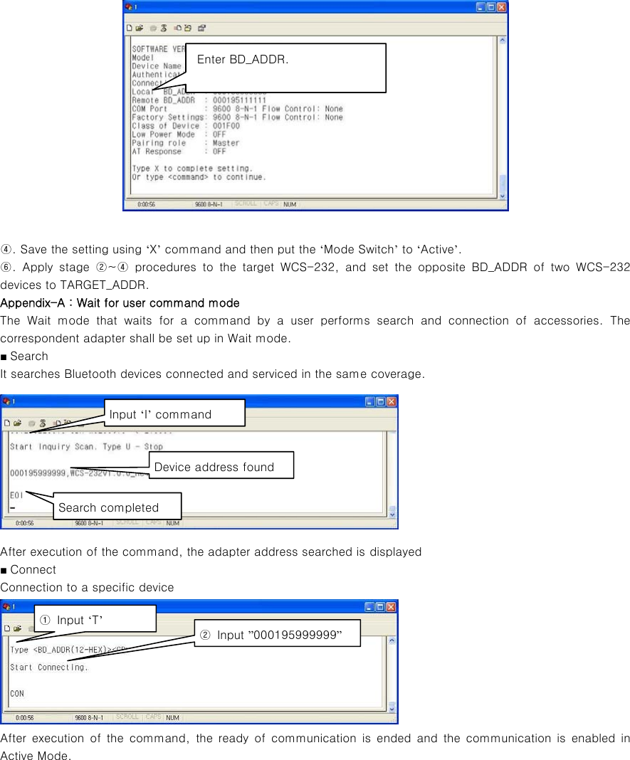
![Appendix–B: Command Items Commands Descriptions Remarks 1. Connection Setting A(addr) Setting for the address of device to be connected addr: 12 numbers in Hex 2. Baud Rate Setting B(BR) Setting for baud rate. BR(Baudrate): 0 ~ 7 0: 1200, 1: 2400 2: 4800, 3: 9600 4: 19200, 5: 38400 6: 57600, 7: 115200 3. PIN Number Setting E(PIN /Enter) Setting for authentication / ciphering. PIN: 16 letters (max) Enter: deactivated After authentication and ciphering, two adapters are to be connected if their PIN numbers are the same. 4. Flow Control Setting F(FC) Setting for flow control FC: 0 ~ 1 0: None 1: Hardware 5. Search Timeout Setting G(TO) Setting for search timeout TO(timeout): 0 ~ 999 Effective in connection mode 2. Default: 10 seconds 6. Maximum Search Setting H(NO) Setting for the maximum number of devices to be searched NO(Respondents): 0 ~ 999 Effective in connection mode 2. Default: 10 7. Search Execution I(TO,NO) Search for Bluetooth devices connected TO(timeout): 0 ~ 999 NO(correspondents): 0 ~ 999Effective in connection mode 2. Search will be completed when it reaches either timeout or the maximum number of correspondents. 8. Search Response Setting J(E/D) Setting whether to respond to search request E: Enabled D: Disenabled Effective in connection mode 1. 9. Power save setting K(E/D) Setting for power save modeE: Enabled D: Disenabled 10. Connection Mode Setting M(mode) Setting for connection modeThe default setting for WCS-232 is connection mode 0, and connection modes 1,2 are used for the connection with other Bluetooth devices.Mode: 0 ~ 2 0: 1:1 connection 1: connection waiting 2: wait for user command 11. Name Setting N(name) Setting for friendly name. Name: 30 letters (max.) Along with the address, it is available for ID. 12. Parity Bit Setting P(PA) Setting for parity bit. PA: 0 ~ 2 0: None 1: Odd 2: Even 13. Connection Timeout Setting Q(TO) Setting for timeout connection. TO(timeout): 0 ~ 999 Effective in connection mode 2 14. Stop Bit Setting S(ST) Setting for stop bit. ST: 0 ~ 1 0: 1 Stop 1: 2 Stop 15. Connection Execution T(addr[,TO]) Connection to a specific device. addr: 12 numbers in Hex [TO](timeout): 0 ~ 999 Effective in connection mode 2 16. Execution Cancellation U Cancellation of device search and connection command. Effective in connection mode 2 17. Setting Confirmation V Displays current setting. Software version information included 18. CoD W(CoD) Setting for class of device. Default: “001F00”](https://usermanual.wiki/SystemBase/WCS232V4/User-Guide-1153076-Page-9.png)
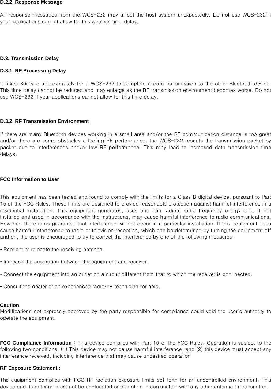
![Setting CoD: 6 numbers in Hex Critical factor for search19. Setting Change Save X Applies edited settings. After command, WCS-232 shall be rebooted. 20. Status Display Z Displays the status of WCS-232. S: Idle P: Pairing C: Connecting A: RF on I: Inquiring 21. Help ?([command]) Displays command list and help. Commands shown are depending on the Current Mode. 22. AT Command Response L(E/D) Setting whether to respond to AT command AT command can be used in mode 2 23. Factory Reset R Setting for factory reset ※ User should change hyper terminal setting value as like Baud rate, Parity bit, Stop bit to assigned factory default value in the Set-up mode, If user has changed factory default’s setting value. Appendix–C: Trouble Shooting D.1. No Data Transmission D.1.1. COM Port Settings Check whether the Baud rate of WCS-232 matches that of its host equipment. Check whether the host equipment has a Data bit setting of 8. WCS-232 supports only 8 Data bit settings. If your host equipment uses 7 Data bit and even or odd parity, it may work with a 8 Data bit and No parity setting. This is valid only when both DCE devices are the WCS-232. In this case, set both WCS-232s] to 8 Data bit and No parity. If one of DCE devices is another Bluetooth device such as Bluetooth USB dongle,7 bit data configurations will not work. Check whether the Parity and Stop bit of WCS-232 match those of your host equipment. WCS-232 supports No parity, Even parity and Odd parity, 1 and 2 Stop bit configurations. Check whether the host equipment of WCS-232 uses Hardware Flow Control. WCS-232 is initially set to Use of Hardware Flow Control. If your host equipment does not use Hardware Flow Control, please disable the Hardware flow control option by referring to ‘5.Operating environment setting’. WCS-232 does not support RS-232 break signal. D.1.2. Pin Assignment WCS-232 is a DCE device. If your host equipment is DTE, plug WCS-232 directly to the host equipment or use straight RS-232 cable. If your host equipment is DCE, use will need to use a cross over RS-232 cable (Null modem cable) or a Male to Male DB9 Null Modem adapter. D.2. Data Loss or Malfunctioning D.2.1. Hardware Flow Control When transmitting large amounts of data with No Hardware Flow Control, WCS-232 may clear the data buffer unexpectedly. The possibility becomes greater as the RF transmission environment becomes worse.](https://usermanual.wiki/SystemBase/WCS232V4/User-Guide-1153076-Page-10.png)