SystemBase WCS232V4 BLUETOOTH SERIAL ADAPTER User Manual menual final
SystemBase Co., Ltd. BLUETOOTH SERIAL ADAPTER menual final
Users Manual
Bluetooth Serial Adapter
WCS-232V4
User Manual
Version 4.0
1.Introduction
WCS-232 converts RS-232 serial signals to Bluetooth RF signals.
■ Product box contains
- RS232 to RF Converter 2EA - User Manual
- USB Power cable 2EA
2. Specifications
Model Name WCS-232V4
Type Bluetooth Serial Adapter
Distance Nom.100m up to 500m using dipole antenna
Voltage 5V ~ 12V/DC
Wireless interface Bluetooth Specification Version 2.0+EDR
Class1
Frequency bandwidth 2402 ~ 2480 MHz
Radio mode Frequency hopping
Channels 79
Modulation GFSK, π/4DQPSK, 8DPSK
Current Max 200 mA (5V DC)
Temperature -20 ~ 55 °C
Antenna +1dBi Stub Antenna
+3dBi Dipole Antenna(optional)
+5dBi Dipole Antenna(optional)
Serial communication 1200 BPS – 115.2 KBPS Full Duplex
8 Data bits
Odd, Even, No Parity
1,2 Stop bits
Flow Control RTS/CTS ON/Off possible,
DTR/DSR/DCD Loop back connected
3. Architecture
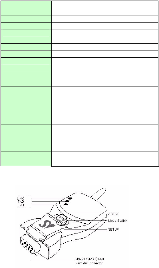
1) External View
2) Mode Switch
Setup Active : Active Mode
Setup Active : Setup Mode
3) LED
- LINK : Turns red when power is supplied
Turns green when remotely linked with the other party
- TxD : Turns green when data is transmitting (turns on faintly only if linked)
- RxD : Turns red when data is receiving
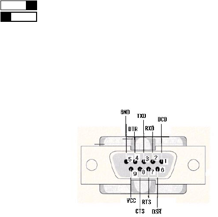
4) Connector
DB-9 Connector Pin-out
4. Installation Procedures
1) Connection
There is no need to install additional programs in your computer or communication devices to use the WCS-232.
Connect the WCS-232 to a serial port at your computer or communication device and supply it with power. Then
you can easily access it as if you were using the existing serial port.
WCS-232 can be powered by the following methods: DC power supply, PC USB port through USB cable or DB9
pin connector (available only if special serial ports are used).
A Bluetooth connection between two devices using the WCS-232 is automatically established when both WCS-
232 are powered on. After that, LINK LED turns red and you are free to use the WCS-232
2) Environment Setting
Since WCS-232s are connected onto the serial port of your PC or communication device, you should specify the
serial port environment information (Baud rate, data bits, parity bit, stop bit, flow control, etc.) and the RF
connection (device name, operating mode, target address, etc.) for mutual communication.
RF connection setting is required only if you communicate with other manufacturer’s Bluetooth devices instead of
the WCS-232 or change the initial setting.
For environment setting, please use “Hyper terminal” included in your Windows’ operating system.
5. Operating Environment Setting
1) Procedures
WCS-232 can set baud rate, parity, stop bit, device name, target adapter and operating mode using Hyper
Terminal.
①. Connect one WCS-232 to the PC serial port and power it on.
②. Run Windows’ Hyper Terminal program.
③. Whenever you change environment setting, you must Set baud rate, data bits, parity and stop bit to
9600-8-NONE-1 (Initial Factory Setting) at Hyper Terminal.
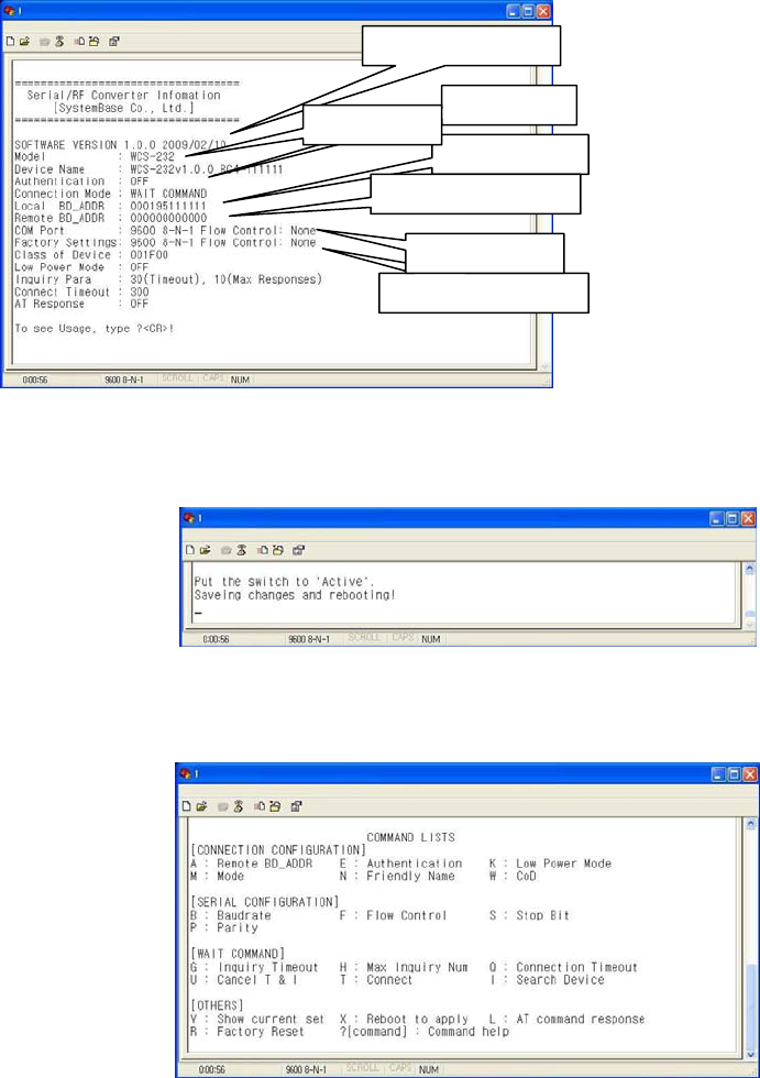
④. Select setup mode at the WCS-232 mode switch. Then software version information will be displayed
⑥. Set up serial port.
⑦. Setup RF connection.
⑧. After completing the setting, be sure to execute ‘X’ command and save, and then the Mode Switch to ‘Active’.
■ Reference:
If you enter ‘?’, the list for all commands is displayed, and if ‘?<command>’, how to use the requested command
is displayed. All commands should be typed with capital letter. All commands and setting values are case-
sensitive.
2) Serial settings
■ Example of Baud Rate setting (9600 bps -> 19200 bps)
① Type ‘B’.
Software version
Authentication
Adapter address
Factory default setting
Target adapter address
Device name
COM port setting
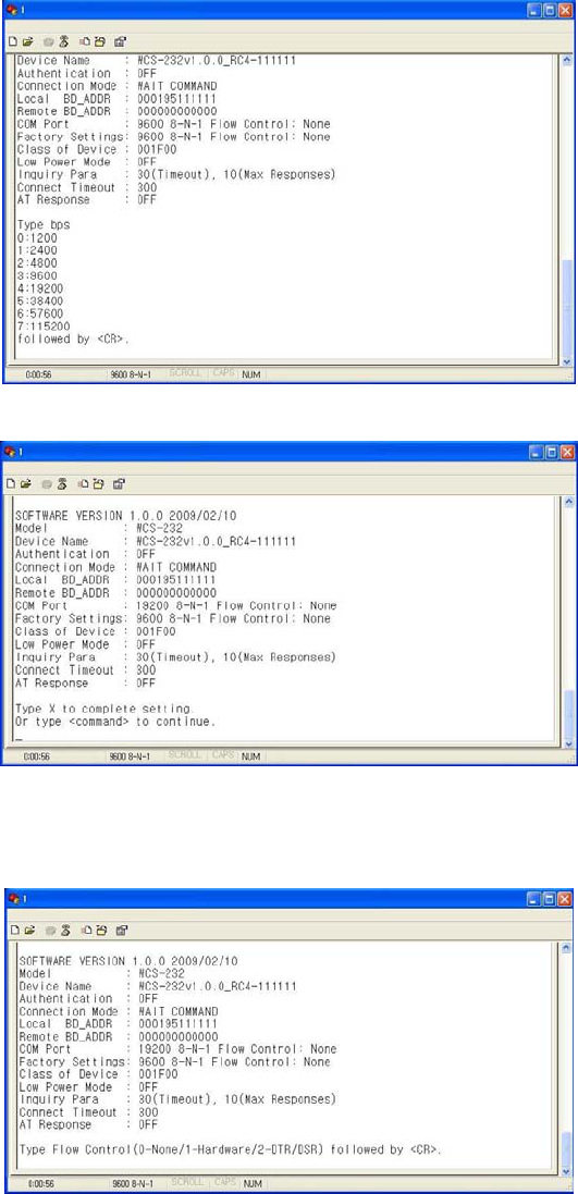
②. Type ‘4’ to select 19200 bps.
③. The set value is shown on the screen again. (All the same in the next procedures)
■ Example of Flow control setting (None -> Hardware)
① Type ‘F’.
②. Type ‘1’ to use hardware flow control.
■ Example of Stop bit setting (1 bit -> 2 bits)
① Type ‘S’.
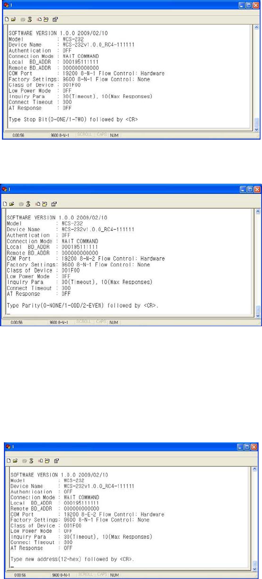
②. Type ‘1’ to change a stop bit to 2 bits..
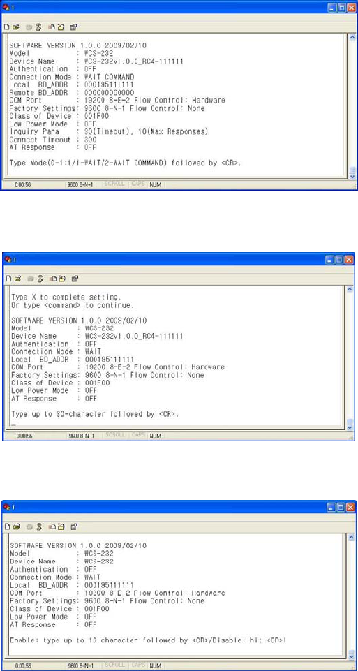
■ Example of Parity bit setting (None -> Even)
①. Type ‘P’.
②. Type ‘2’ to change to even parity.
3) RF Connection setting
This is necessary only if you communicate with other manufacturer’s Bluetooth devices instead of the WCS-232
or change the initial settings.
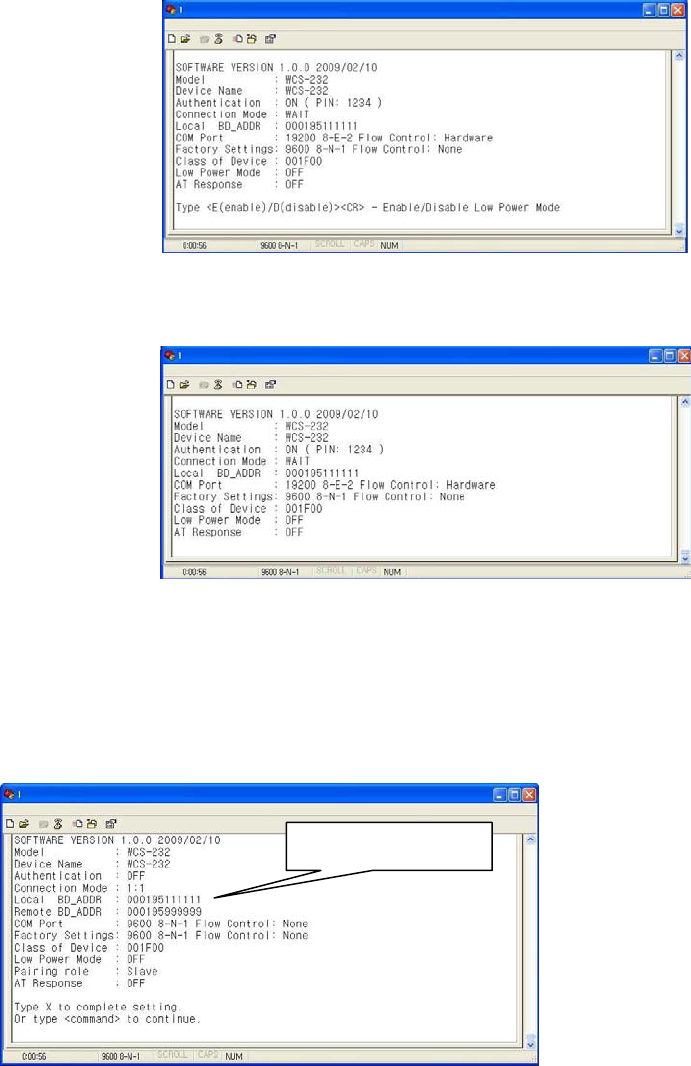
■ Example of Target Address setting
(00:00:00:00:00:00 -> 00:02:78:01:EF:BC)
①. Type ‘A’.
②. Type the target address to be changed. You have to enter the 12-digit hexadecimal address. After typing
“00027801EFBC”, press ‘Enter’ key.
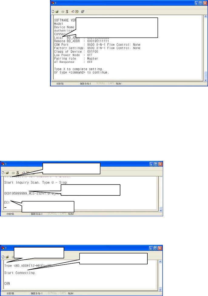
■ Example of connection mode setting (WAIT COMMAND -> WAIT)
①. First, enter ‘M’ to display the way to use the requested command. To set the connection mode at Wait mode,
the input value shall be ‘0’.
② Type ‘M’.
③. Type ‘1’.
■ Example of device name setting
①. Type ‘N’.
②. Enter the desire device name and press ‘Enter’ key (however, up to 30 alphanumeric characters possible).
■ Example of setting PIN
①. Type ‘E’.
② Enter the desire PIN value and press ‘Enter’ key. (However, up to 16 alphanumeric characters possible)
■ Example of setting low power mode
①. Enter ‘K.’ If you want to set up a low power mode, enter ‘E’, or if not, enter ‘D’.
■ Display Device Information
①. Type ‘V’.
②. All current information is displayed. At this time, verify that the values are identical to the ones you have once
set.
■ WCS-232 Pair Setting
WCS-232 always perform 1:1 communication in pairs.
The following example showing how to set up the destination WCS-232 address.
①. Set baud rate, data bits, parity and stop bit to 9600-8-NONE-1 at Hyper Terminal.
②. Connect one of WCS-232s to your PC serial port and put ‘Mode Switch’ to Setup Mode. and Record
displayed BD_ADDR.
③. Remove WCS-232(Used at stage ②) from your PC serial port, and connect the target WCS-232 and then set
the registered BD_ADDR using ‘A’ command.
Record BD_ADDR.
④. Save the setting using ‘X’ command and then put the ‘Mode Switch’ to ‘Active’.
⑥. Apply stage ②~④ procedures to the target WCS-232, and set the opposite BD_ADDR of two WCS-232
devices to TARGET_ADDR.
Appendix-A : Wait for user command mode
The Wait mode that waits for a command by a user performs search and connection of accessories. The
correspondent adapter shall be set up in Wait mode.
■ Search
It searches Bluetooth devices connected and serviced in the same coverage.
After execution of the command, the adapter address searched is displayed
■ Connect
Connection to a specific device
After execution of the command, the ready of communication is ended and the communication is enabled in
Active Mode.
Enter BD_ADDR.
Input ‘I’ command
Device address found
Search completed
① Input ‘T’
② Input ”000195999999”

Appendix–B: Command
Items Commands Descriptions Remarks
1. Connection
Setting
A(addr) Setting for the address of
device to be connected
addr: 12 numbers in Hex
2. Baud Rate
Setting
B(BR) Setting for baud rate.
BR(Baudrate): 0 ~ 7
0: 1200, 1: 2400
2: 4800, 3: 9600
4: 19200, 5: 38400
6: 57600, 7: 115200
3. PIN
Number
Setting
E(PIN
/Enter)
Setting for authentication /
ciphering.
PIN: 16 letters (max)
Enter: deactivated
After authentication and
ciphering, two adapters
are to be connected if
their PIN numbers are
the same.
4. Flow
Control
Setting
F(FC) Setting for flow control
FC: 0 ~ 1
0: None
1: Hardware
5. Search
Timeout
Setting
G(TO) Setting for search timeout
TO(timeout): 0 ~ 999
Effective in connection
mode 2.
Default: 10 seconds
6. Maximum
Search
Setting
H(NO) Setting for the maximum
number of devices to be
searched
NO(Respondents): 0 ~ 999
Effective in connection
mode 2.
Default: 10
7. Search
Execution
I(TO,NO) Search for Bluetooth devices
connected
TO(timeout): 0 ~ 999
NO(correspondents): 0 ~ 999
Effective in connection
mode 2.
Search will be
completed when it
reaches either timeout
or the maximum number
of correspondents.
8. Search
Response
Setting
J(E/D) Setting whether to respond to
search request
E: Enabled
D: Disenabled
Effective in connection
mode 1.
9. Power
save setting
K(E/D) Setting for power save mode
E: Enabled
D: Disenabled
10.
Connection
Mode Setting
M(mode) Setting for connection mode
The default setting for WCS-
232 is connection mode 0,
and connection modes 1,2
are used for the connection
with other Bluetooth devices.
Mode: 0 ~ 2
0: 1:1 connection
1: connection waiting
2: wait for user
command
11. Name
Setting
N(name) Setting for friendly name.
Name: 30 letters (max.)
Along with the address,
it is available for ID.
12. Parity Bit
Setting
P(PA) Setting for parity bit.
PA: 0 ~ 2
0: None
1: Odd
2: Even
13.
Connection
Timeout
Setting
Q(TO) Setting for timeout
connection.
TO(timeout): 0 ~ 999
Effective in connection
mode 2
14. Stop Bit
Setting
S(ST) Setting for stop bit.
ST: 0 ~ 1
0: 1 Stop
1: 2 Stop
15.
Connection
Execution
T(addr[,TO]) Connection to a specific
device.
addr: 12 numbers in Hex
[TO](timeout): 0 ~ 999
Effective in connection
mode 2
16. Execution
Cancellation
U Cancellation of device search
and connection command.
Effective in connection
mode 2
17. Setting
Confirmation
V Displays current setting. Software version
information included
18. CoD W(CoD) Setting for class of device. Default: “001F00”

Setting CoD: 6 numbers in Hex Critical factor for search
19. Setting
Change Save
X Applies edited settings. After command, WCS-
232 shall be rebooted.
20. Status
Display
Z Displays the status of WCS-
232.
S: Idle P: Pairing
C: Connecting
A: RF on
I: Inquiring
21. Help ?([command]) Displays command list and
help.
Commands shown are
depending on the
Current Mode.
22. AT
Command
Response
L(E/D) Setting whether to respond to
AT command
AT command can be
used in mode 2
23. Factory
Reset
R Setting for factory reset
※ User should change hyper terminal setting value as like Baud rate, Parity bit, Stop bit to
assigned factory default value in the Set-up mode, If user has changed factory default’s
setting value.
Appendix–C: Trouble Shooting
D.1. No Data Transmission
D.1.1. COM Port Settings
Check whether the Baud rate of WCS-232 matches that of its host equipment.
Check whether the host equipment has a Data bit setting of 8. WCS-232 supports only 8 Data bit settings. If your
host equipment uses 7 Data bit and even or odd parity, it may work with a 8 Data bit and No parity setting. This
is valid only when both DCE devices are the WCS-232. In this case, set both WCS-232s] to 8 Data bit and No
parity. If one of DCE devices is another Bluetooth device such as Bluetooth USB dongle,7 bit data configurations
will not work.
Check whether the Parity and Stop bit of WCS-232 match those of your host equipment. WCS-232 supports No
parity, Even parity and Odd parity, 1 and 2 Stop bit configurations.
Check whether the host equipment of WCS-232 uses Hardware Flow Control. WCS-232 is initially set to Use of
Hardware Flow Control. If your host equipment does not use Hardware Flow Control, please disable the Hardware
flow control option by referring to ‘5.Operating environment setting’.
WCS-232 does not support RS-232 break signal.
D.1.2. Pin Assignment
WCS-232 is a DCE device. If your host equipment is DTE, plug WCS-232 directly to the host equipment or use
straight RS-232 cable. If your host equipment is DCE, use will need to use a cross over RS-232 cable (Null
modem cable) or a Male to Male DB9 Null Modem adapter.
D.2. Data Loss or Malfunctioning
D.2.1. Hardware Flow Control
When transmitting large amounts of data with No Hardware Flow Control, WCS-232 may clear the data buffer
unexpectedly. The possibility becomes greater as the RF transmission environment becomes worse.
D.2.2. Response Message
AT response messages from the WCS-232 may affect the host system unexpectedly. Do not use WCS-232 If
your applications cannot allow for this wireless time delay.
D.3. Transmission Delay
D.3.1. RF Processing Delay
It takes 30msec approximately for a WCS-232 to complete a data transmission to the other Bluetooth device.
This time delay cannot be reduced and may enlarge as the RF transmission environment becomes worse. Do not
use WCS-232 If your applications cannot allow for this time delay.
D.3.2. RF Transmission Environment
If there are many Bluetooth devices working in a small area and/or the RF communication distance is too great
and/or there are some obstacles affecting RF performance, the WCS-232 repeats the transmission packet by
packet due to interferences and/or low RF performance. This may lead to increased data transmission time
delays.
FCC Information to User
This equipment has been tested and found to comply with the limits for a Class B digital device, pursuant to Part
15 of the FCC Rules. These limits are designed to provide reasonable protection against harmful interference in a
residential installation. This equipment generates, uses and can radiate radio frequency energy and, if not
installed and used in accordance with the instructions, may cause harmful interference to radio communications.
However, there is no guarantee that interference will not occur in a particular installation. If this equipment does
cause harmful interference to radio or television reception, which can be determined by turning the equipment off
and on, the user is encouraged to try to correct the interference by one of the following measures:
• Reorient or relocate the receiving antenna.
• Increase the separation between the equipment and receiver.
• Connect the equipment into an outlet on a circuit different from that to which the receiver is con-nected.
• Consult the dealer or an experienced radio/TV technician for help.
Caution
Modifications not expressly approved by the party responsible for compliance could void the user’s authority to
operate the equipment.
FCC Compliance Information : This device complies with Part 15 of the FCC Rules. Operation is subject to the
following two conditions: (1) This device may not cause harmful interference, and (2) this device must accept any
interference received, including interference that may cause undesired operation
RF Exposure Statement :
The equipment complies with FCC RF radiation exposure limits set forth for an uncontrolled environment. This
device and its antenna must not be co-located or operation in conjunction with any other antenna or transmitter.