Systems and Technology STAVL1450 GPS Vehicle Tracking Device User Manual
Systems & Technology Corp. GPS Vehicle Tracking Device
UserManual.wiki
>
Systems and Technology
>
STAVL1450 User Manual
User Manual
Navigation menu
Upload a User Manual
Namespaces
Wiki Guide
HTML
PDF
Info
Views
User Manual
Discussion / Help
Navigation
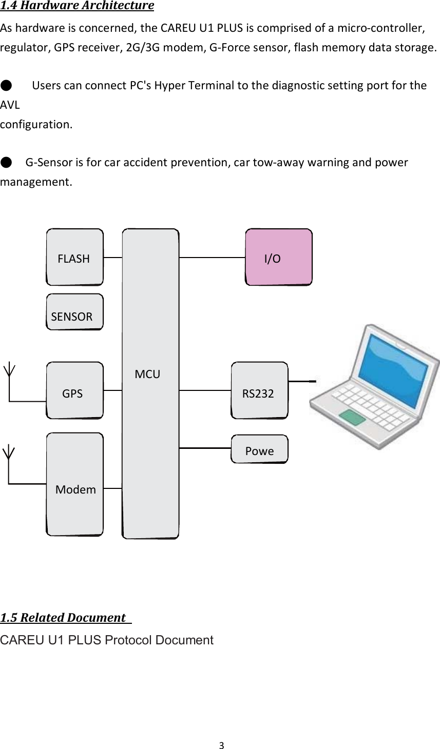
![7 Stop Bits --> 1 Flow Control --> None 7. In the connection that you have just set up, click File | Properties. Select the [Connect To] tab. From the [Connect using] drop down list, select the correct com port. 8. In the File menu, click Properties. Click the [Settings] tab. Press the ASCII Setup button.](https://usermanual.wiki/Systems-and-Technology/STAVL1450/User-Guide-2498928-Page-10.png)
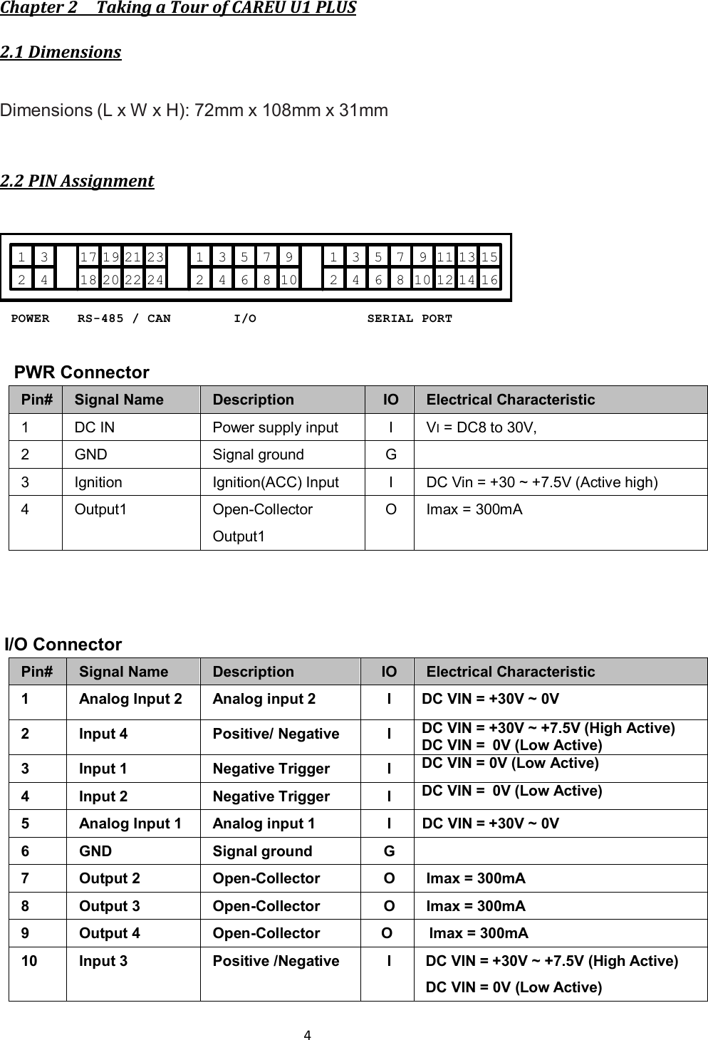
![8 9. In the [ASCII Sending] group box. Select both Send line ends with line feeds and Echo typed characters locally. Press the OK button. 10.Connect your the CAREU U1 PLUS device and power on,The device startup message will be displayed.](https://usermanual.wiki/Systems-and-Technology/STAVL1450/User-Guide-2498928-Page-11.png)
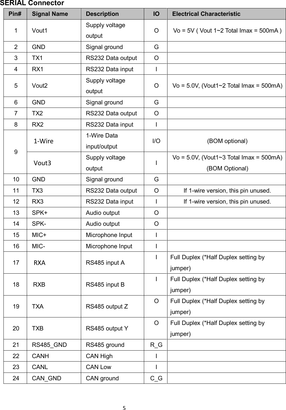
![9 11. In [HyperTerminal] window, type in the command "AT$VERSION?" and press the Enter key. The hardware and firmware version will show. As long as your [HyperTerminal] window appears as the screenshot below, a connection between the device and your system has already been built up and working. It is time to send all configuration commands. 3.2 Communication Settings The CAREU U1 PLUS Vehicle Tracker communicates with your control center by either SMS or 2G/3G (TCP/UDP). Before the device is installed into a vehicle, communication parameters should be set. 1. SMS Configuration Use AT$SMSDST command to set a SMS control center phone number or short code. For example, if the SMS control center phone number is +886123456789, the AT$SMSDST command to be issued into HyperTerminal should be: AT$SMSDST=+886123456789 OK](https://usermanual.wiki/Systems-and-Technology/STAVL1450/User-Guide-2498928-Page-12.png)