Systems and Technology STAVL1515 GPS Vehicle Tracking Device User Manual
Systems & Technology Corp. GPS Vehicle Tracking Device
User Manual

CAREU U1
PLUS
User
Gu
CAREU U1 LITE PLUS
User
Guide
Version: 0.1
Reference No.: AVL
Date: 2015/4/1
SYSTEMS & TECHNOLOGY
COR
General Information
If any breakdown occurs due to the operation of the described product or
users’ improper handling in accordance with the instructions of the
document, S&T shall be liable for the General Conditions based on the
delivery of the described product and the content of the document. This
product is not designed for the use of life support appliances, devices or
systems and thence a malfunction of the product might reasonably be
expected to make personal injury. S&T customers using or selling this
product for such applications will take the risk on their own; therefore, it must
be agreed S&T will be fully indemnified from any damages due to illegal use
or resale. All information in this document is subject to change without notice
at any time.
Disclaimer
The information, specification, images and photos in this user guide are
subject to change without notice and without obligation to notify any person
of such revision change.
Copyright
This user guide, including all photographs, illustrations and software, to
name a few, is protected under international copyright laws, with all rights
reserved. This document contains confidential, restricted and proprietary
information that it has been exclusively prepared for the internal use of
certain designated S&T employees, and may not be duplicated or distributed,
in whole or in part, without the prior written consent of S&T’s authorized
delegates. Any illegal copying and disclosure of the document are absolutely
prohibited, and violators are liable to the damages caused.
© Systems & Technology Corp. All Rights Reserved
Table of Contents
Chapter 1 introduction. ......................................................................................... 1
1.1Features ............................................................................................................ 1
1.2 Scope ................................................................................................................ 1
1.3 Overview .......................................................................................................... 1
1.4 Hardware Architecture .................................................................................... 3
1.5 Related Document ........................................................................................... 3
Chapter 2 Taking a Tour of CAREU U1 LITE PLUS ........................................... 4
2.1 Dimensions ....................................................................................................... 4
2.2 PIN Assignment ................................................................................................ 4
Chapter 3 Getting Started with CAREU U1 LITE PLUS .................................... 5
3.1 Device Configuration ........................................................................................ 5
3.2 Communication Settings .................................................................................. 9
3.3 GPS Tracking Configurations .......................................................................... 10
3.4 Firmware Upgrade ......................................................................................... 11
Chapter 4 Technical Specification ............................................................... 12
Chapter 5 Regulation .................................................................................. 15
Chapter 6 Safety Information ..................................................................... 16

1
Chapter 1 introduction.
Designed with the latest GPS technology, the CAREU U1 LITE PLUS delivers
positioning message by wireless transmission to GIS platform, and then helps
back-end users proceed with the analysis and the applications of vehicle transport,
management, anti-theft, security and tracking.
A microcontroller can probe location and command data at regular intervals, derive
actions from location, peripheral and control data, and execute such actions.
Peripheral data indicates the status of various peripherals connected to and/or
controlled by the device. Among the best features of the CAREU U1 LITE PLUS
Vehicle Tracker, in particular, they transmit data in ASCII mode (Intellitrac X Series
compatible mode) or binary mode.
1.1 Features
● SMS,GPRS/UMTS/HSPA TCP/UDP, USSD, FTP
● Real-time tracking (Time, Distance Interval or Intelligent Mode, and Heading)
● Firmware upgrade over the air ( form FTP)
● Journey report wireless download
● Battery low alert
● Geofence reports
● Mileage reports
● User-defined reports
● 6-Axis Sensor
● NMEA-0183 Output for Navigation
● GPS Antenna Destroyed Alarm
● CAN BUS interface (optional)
1.2 Scope
This document will guides you to start the CAREU U1 LITE PLUS Vehicle Tracker.
However,as this document contains basic device configuration only, please see the
CAREU U1 LITE PLUS Protocol Document for the advanced information.
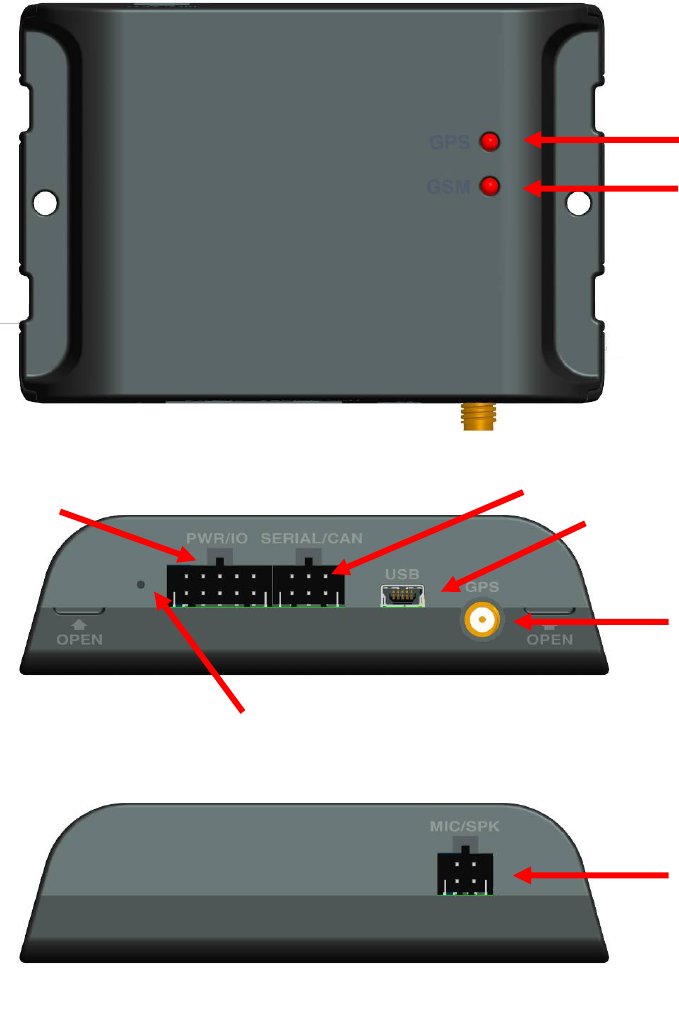
1.3 Overview
Device Overview
2
1. GPS LED
2. GSM LED
3. Power & I/O Connector
4. RS-232/CAN Connector
5. USB Connector
6. GPS Antenna Connector
7. Reset Switch
6. Speaker/MIC Connector
2
1
3 4 5
6
7
8
3
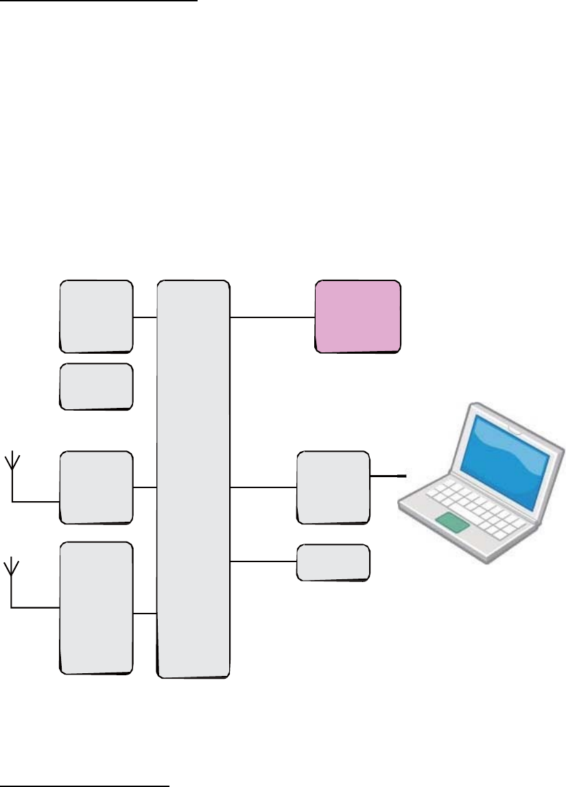
1.4 Hardware Architecture
As hardware is concerned, the CAREU U1 LITE PLUS is comprised of a
micro-controller, regulator, GPS receiver, 2G/3G modem, G-Force sensor, flash
memory data storage.
● Users can connect PC's Hyper Terminal to the diagnostic setting port for the
AVL configuration.
● G-Sensor is for car accident prevention, car tow-away warning and power
management.
FLASH I/O
SENSOR
MCU
GPS RS232
Powe
Modem
1.5 Related Document
CAREU U1 LITE PLUS Protocol Document
4
Chapter 2 Taking a Tour of CAREU U1 LITE PLUS
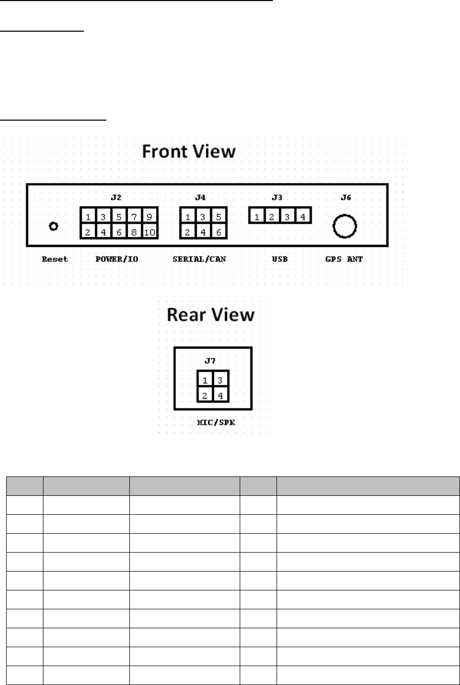
2.1 Dimensions
Dimensions (L x W x H): 105.5mm x 72mm x 28.5mm
2.2 PIN Assignment
PWR/IO Connector
Pin#
Signal Name Description IO Electrical Characteristic
1 DC IN Power supply input I DCIN = DC 8V to 30V,
2 GND Signal ground G
3 Ignition Ignition(ACC) Input I DC Vin = +30 ~ +7.5V (Active high)
4 Output1 Open-Drain output O Imax = 750mA
5 Output2 Open-Drain output O Imax = 750mA
6 Input 1 Negative Trigger I Low Active
7 Input 2 Positive Trigger I High Active
8 Input 3 Negative Trigger I Low Active
9 1-Wire 1-Wire Data I/O
10 Analog Input1 Analog Input1 I Voltage Range DC 0~+30V
5
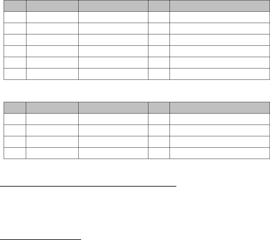
Serial/CAN Connector
Pin#
Signal Name Description IO Electrical Characteristic
1 RS232-TX RS232 Data output O
2 RS232RX RS232 Data Input I
3 Vout Supply voltage output
O Vo = 5V ( Vout Total Imax = 500mA )
4 GND Ground G
5 CAN_H CAN_H I/O
6 CAN_L CAN_L I/O
MIC/SPK Connector
Pin#
Signal Name Description IO Electrical Characteristic
1 MIC+ Microphone Input I
2 MIC- Microphone Input I
3 SPK+ Audio output O
4 SPK- Audio output O
Chapter 3 Getting Started with CAREU U1 LITE PLUS
To install the the CAREU U1 LITE PLUS device, follow the instructions below
for basic operations
3.1 Device Configuration
1. Connected the serial port 1 to PC COM port
2. In Windows desktop, click Start | All Programs | Accessories | Communications
| HyperTerminal.
3. If you are prompted to input the information of your location, complete them to
proceed.
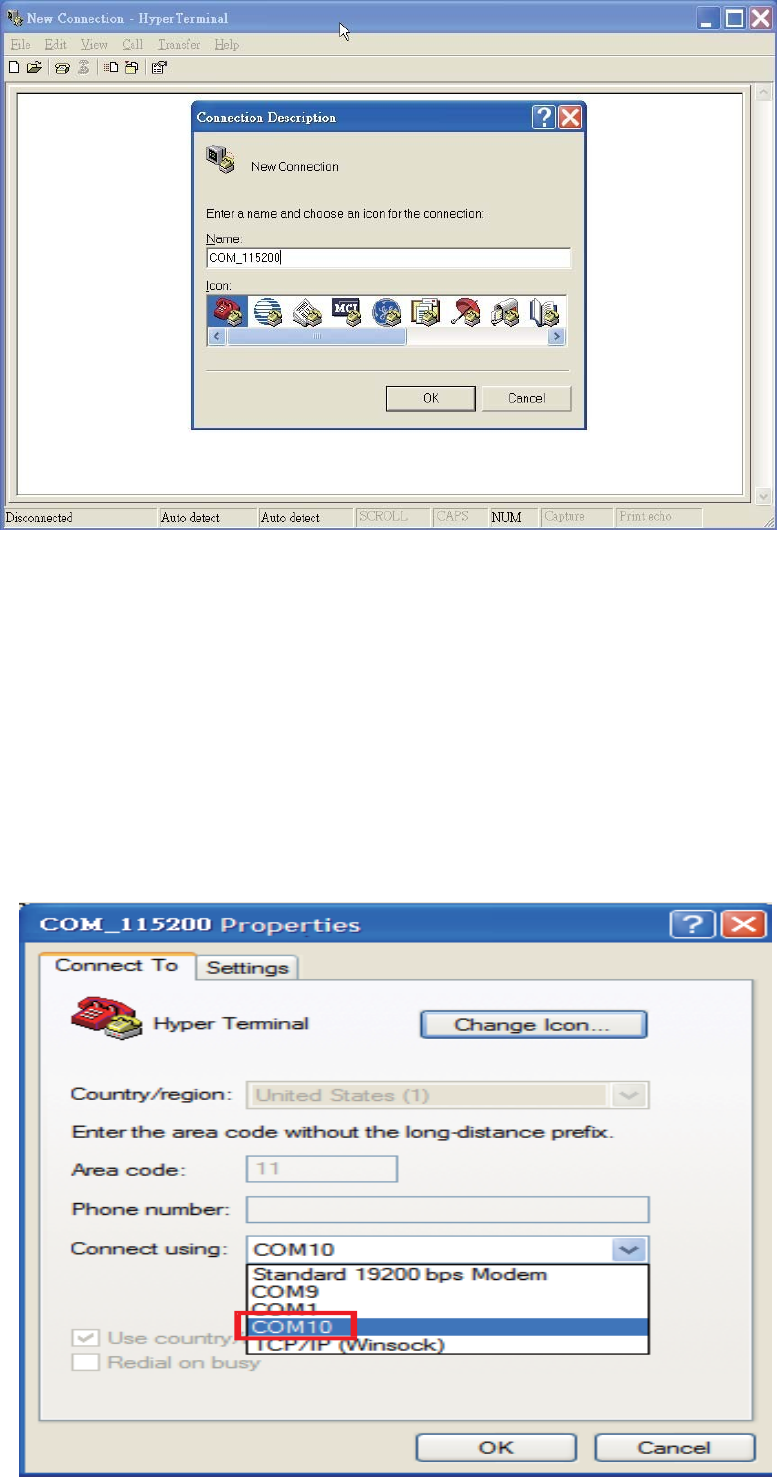
4. On the File menu of HyperTerminal, click New Connection.
5. In the Name box, type a name that describes the connection. In the Icon box, click
an appropriate icon. Press the OK button to proceed.
6
6. For Com port properties, configure as follows: Baud Rate --> 115200 bps
Data Bits --> 8
Parity --> None
Stop Bits --> 1
Flow Control --> None
7. In the connection that you have just set up, click File | Properties. Select the
[Connect To] tab. From the [Connect using] drop down list, select the correct com
port.
7
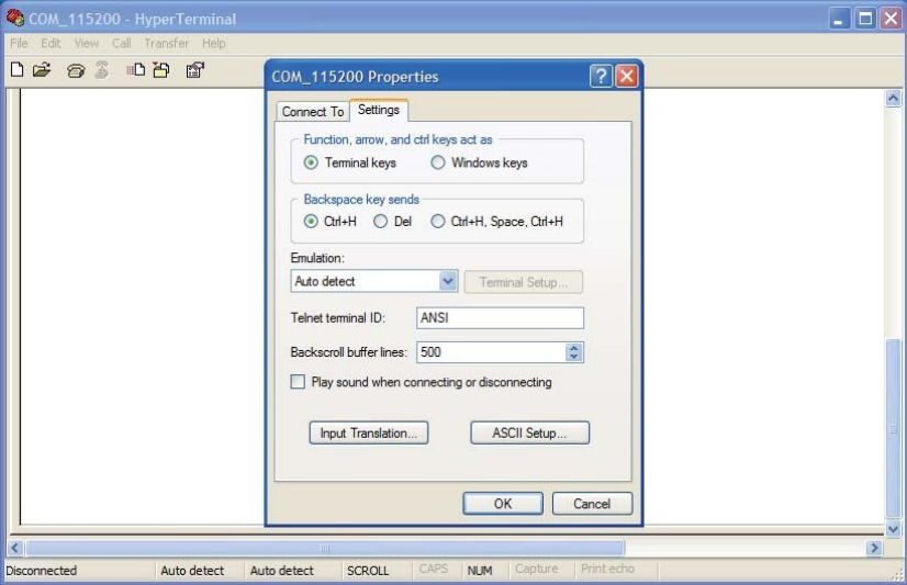
8. In the File menu, click Properties. Click the [Settings] tab. Press the ASCII Setup
button.
9. In the [ASCII Sending] group box. Select both Send line ends with line feeds
and Echo typed characters locally. Press the OK button.
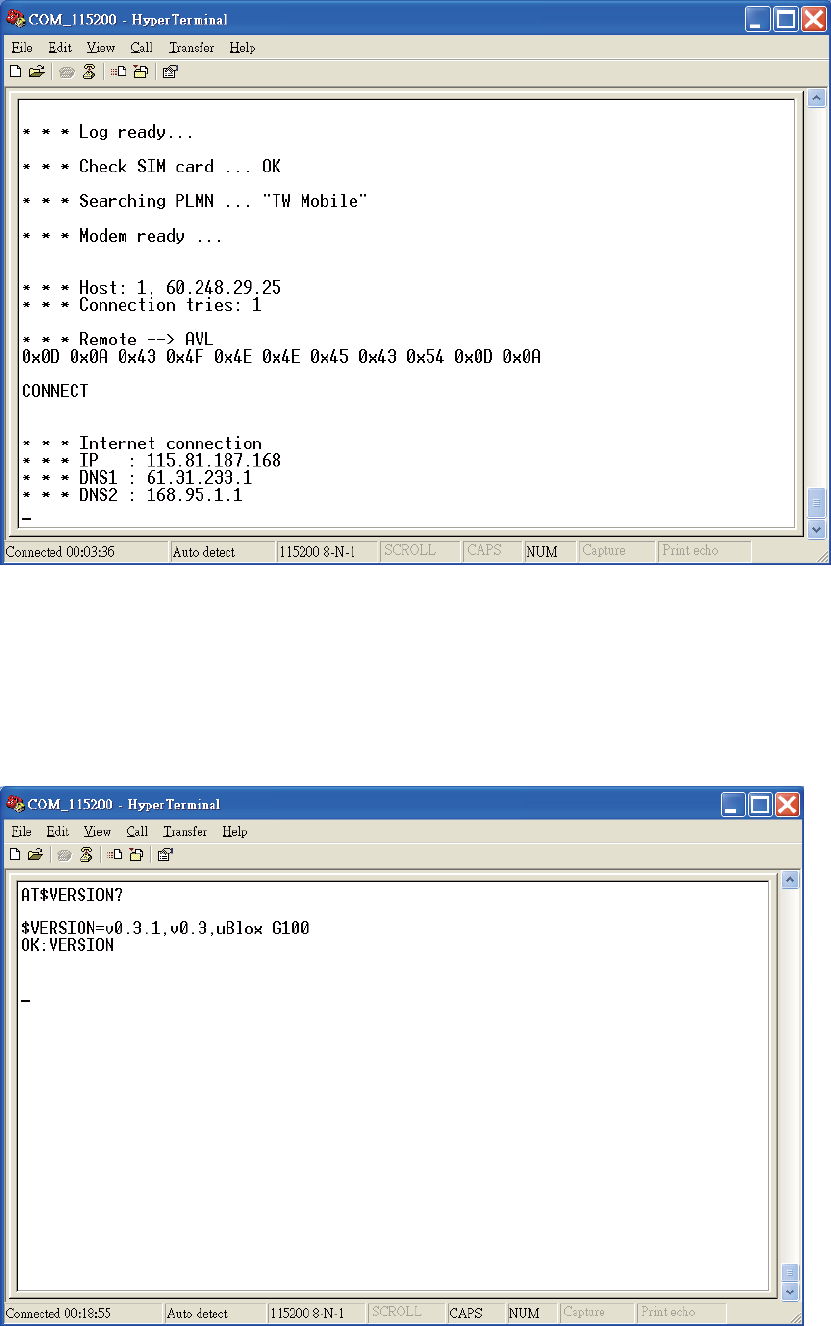
10.Connect your the CAREU U1 LITE PLUS device and power on,The device startup
message will be displayed.
8
11. In [HyperTerminal] window, type in the command "AT$VERSION?" and press
the Enter key. The hardware and firmware version will show. As long as your
[HyperTerminal] window appears as the screenshot below, a connection
between the device and your system has already been built up and working. It
is time to send all configuration commands.

9
3.2 Communication Settings
The CAREU U1 LITE PLUS Vehicle Tracker communicates with your control center by
either SMS or 2G/3G (TCP/UDP). Before the device is installed into a vehicle,
communication parameters should be set.
1. SMS Configuration
Use AT$SMSDST command to set a SMS control center phone number or short code.
For example, if the SMS control center phone number is +886123456789, the
AT$SMSDST command to be issued into HyperTerminal should be:
AT$SMSDST=+886123456789
OK
Then you can try to use cellular phone or SMS gateway to send a SMS message to
the CAREU U1 LITE PLUS device. Send a SMS message -->"AT$MODID?"
Device will response:
$MODID=101000001
OK
This proves a successful mobile phone SMS connection.
2.WirelessConfiguration
Set GPRS servers by using the folloiwng commands:
AT$APN=internet,username,password (APN=internet, Username=username,
Password=password) OK
AT$HOSTS=1,0,60.148.19.10,6000
(Server IP address = 60.148.19.10 and Port number =6000) OK
AT$RETRY=5,10 (Message retry settings) OK
AT$IPTYPE=1 (Using TCP/IP mode) OK
AT$GPRSEN=1 (GPRS enable) OK
10
AT$HB=60,1 (Heartbeat setting) OK
Please refer to the CAREU U1 LITE PLUS Protocol Document for more command
details.
3.3 GPS Tracking Configurations
After the device communication settings are done, the remote GPS tracking is ready
to function. The setting of GPS tracking can be done by using AT$PDSR command.
For example,
AT$PDSR=1,30,0,0,2,0,0,1,0 (Tracking through GPRS by time interval 30 seconds)
OK
For simple testing GPRS, run the TCP Server U-Series software which is provided by
S&T. It is simple server software that can wait for device connection and data.
For advanced testing, you need the software Intelli TracerPlus. Please request this
software through your sales contact.
11
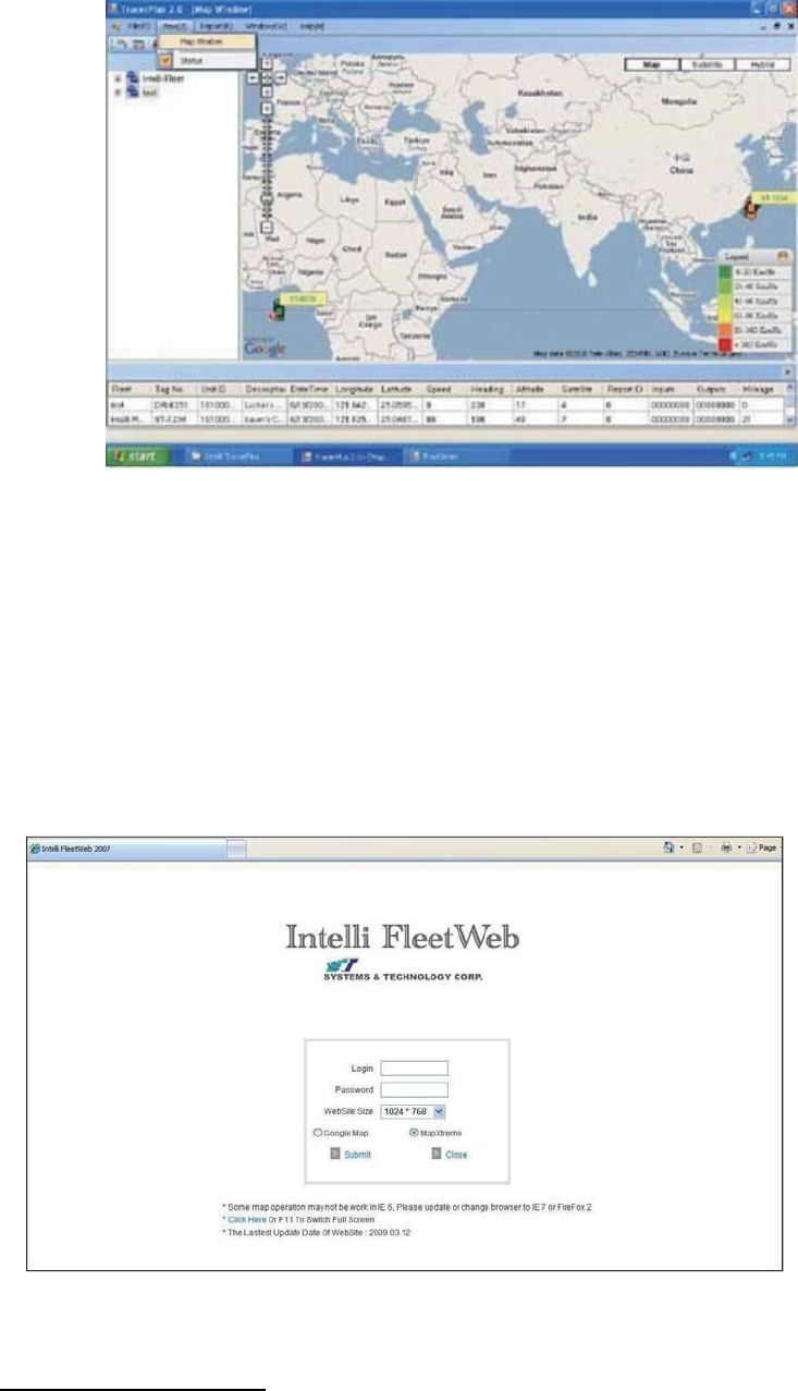
You can also apply for a testing account from S&T's FleetWeb solution through your
sales contact.
The main page of the Intelli FleetWeb appears as below:
3.4 Firmware Upgrade
The firmware of the CAREU U1 LITE PLUS can only be updated through USB interface.
With the firmware loader tool provided by S&T, firmware update can be done for
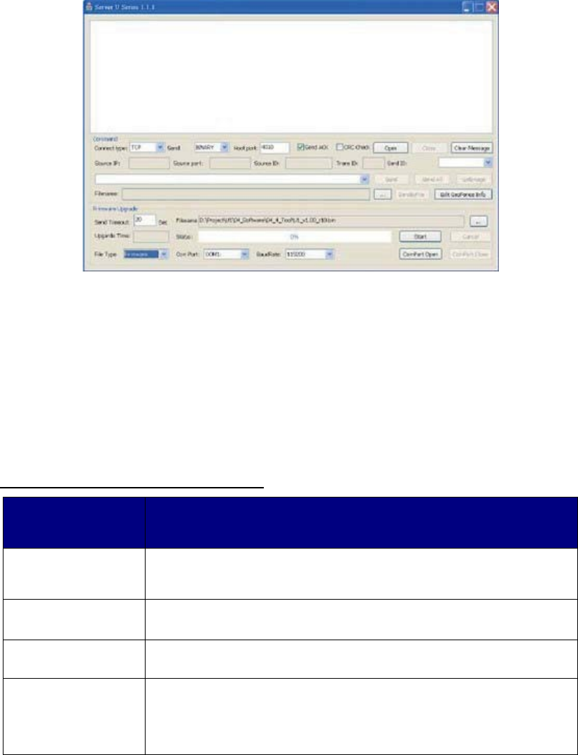
12
the device. Such firmware loader runs on Windows-based systems. To upgrade the
firmware, follow the procedure below
1. Connect the device to your PC with the USB cable.
2. Connect the device to power.
3. Power on the device.
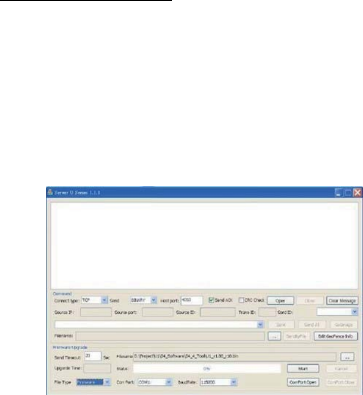
4. Run ServerUSeries.exe. A window displays as follows:
5. Press browse the button to browse to the firmware provided by S&T.
6. Press the Start button to run the firmware program.
7. After the writing progresses to 100%, it takes about 20 seconds for the update
to completes.
8. Firmware update completes.
Chapter 4 Technical Specification
Hardware
Requirements
Description
CPU STM32F103RCT6 (ARM Cotex-M3) 72MHz
STM32F105RCT6 (ARM Cotex-M3) 72MHz/CAN Version
Internal Memory
256Kbyte Flash/48Kbyte RAM
External Memory Default 8Mbytes, (512Mbytes for Debug only).
Cellullar Cellullar Module:
Vendor: uBlox SARA-G350(2G) / SARA-U2(3G)
Frequency: 850/900/1800/1900/2100 MHZ

13
Antenna: Internal
GPS GPS Module:
Vendor: uBlox MAX-M8Q/W
Sensitivity: -167 dB ( GPS & GLONASS )
-165 dB (GPS & BeiDou )
-166 dB (GPS )
Antenna: External
Time to First Fix:
1. Cold Start: 26 Seconds at open sky ( GPS & GLONASS )
27 Seconds at open sky ( GPS & BeiDou )
29 Seconds at open sky ( GPS )
2. Hot Start: 1 Second
3. Aided starts: 2 Seconds at open sky ( GPS & GLONASS )
3 Seconds at open sky (GPS & BeiDou )
2 Seconds at open sky (GPS )
I/O(standard)
Analog Input x 1
A. Voltage Range: 0-30 V
B. Resolution: 12 bit
Digital Input x 4:
A. 1 Postive Active( ACC)
B. 2 Negative Trigger
C. 1 Positive
Digital Output x 2
Sink Current=750mA Maximum
Communication
Interface
RS-232 X 1
USB2.0 Full Speed
CAN interface X 1 (Must to replace STM32F105xxx MCU )
1-wire DS2482-100
Main power
Remove detect
Yes
GPS open/short
detect
Yes
SIM CARD SIM Card Access: External
Battery Life Backup Battery: 950mA
Battery Type Lithium Ion
Sensor 3 axis sensor for motion detection
6 axis (optional)
AGPS Yes
14
Temperature Operating: –20 °C to +60 °C(With Battery)
Operating: –20 °C to +70 °C(Without Battery)
Storage: –20 °C to +80°C
Logging TBD positions
User Report TBD Sets
Note: The specification herein is subject to change without prior notice.
Systems & Technology Corp. (S&T), founded in 1987, is a market leader in Automatic
Vehicle Locating (AVL) solutions, Geographical Information Systems (GIS) and
navigation. It has formed a professional development team to innovate the most
advanced and comprehensive GPS tracking products for the customers and has built
a global service network to provide non-stop services and support.
With the well-established marketing networks of over 100 distributors in the world,
S&T is your trustworthy tracking solution provider. For more product information,
please contact S&T by Email, phone or fax.
Web Site
http://www.systech.com.tw
Email
avl@systech.com.tw
Phone
+886 2 26981599
Fax
+886 2 26981211

15
Chapter 5 Regulation
Federal Communication Commission Interference Statement
This device complies with Part 15 of the FCC Rules. Operation is subject to the
following two conditions: (1) This device may not cause harmful interference, and (2)
this device must accept any interference received, including interference that may
cause undesired operation.
This equipment has been tested and found to comply with the limits for a Class B
digital device, pursuant to Part 15 of the FCC Rules. These limits are designed to
provide reasonable protection against harmful interference in a residential
installation. This equipment generates, uses and can radiate radio frequency energy
and, if not installed and used in accordance with the instructions, may cause harmful
interference to radio communications. However, there is no guarantee that
interference will not occur in a particular installation. If this equipment does cause
harmful interference to radio or television reception, which can be determined by
turning the equipment off and on, the user is encouraged to try to correct the
interference by one of the following measures:
Reorient or relocate the receiving antenna.
Increase the separation between the equipment and receiver.
Connect the equipment into an outlet on a circuit different from that
to which the receiver is connected.
Consult the dealer or an experienced radio/TV technician for help.
FCC Caution:
Any changes or modifications not expressly approved by the party responsible
for compliance could void the user's authority to operate this equipment.
This transmitter must not be co-located or operating in conjunction with any
other antenna or transmitter.
16
Radiation Exposure Statement:
This equipment complies with FCC radiation exposure limits set forth for an
uncontrolled environment. This equipment should be installed and operated with
minimum distance 20cm between the radiator & your body.
Chapter 6 Safety Information