TAIDOC TECHNOLOGY 9030A01 TD-9030A User Manual Attachment 3
TAIDOC TECHNOLOGY CORP. TD-9030A Attachment 3
User Manual

A1.0 - 1 of 7
User Manual
TD-9030A
Brand Name: TaiDoc
FCC ID: TM79030A01
Version 1.0
2014-07

A1.0 - 2 of 7
Description:
The TD-9030A is a low power and low costs Bluetooth 4.0 BLE module based
on the 32 bit ARMR Cortex™-M0 CPU .Perfect for communication and cable
replacement between your device and a smartphone, computer or other
devices. It is easy to setup and use thanks to real and virtual UART interface
and AT commands.
Key Features
2.4 GHz transceiver
-93 dBm sensitivity in Bluetooth® low energy mode
250 kbps, 1 Mbps, 2 Mbps supported data rates
TX Power -20 to +4 dBm in 4 dB steps
TX Power -30 dBm Whisper mode
13 mA peak RX, 10.5 mA peak TX (0 dBm)
RSSI (1 dB resolution)
ARM® Cortex™-M0 32 bit processor
275 μA/MHz running from flash memory
150 μA/MHz running from RAM
Memory
256 kB or128 kB embedded flash program
memory
16 kB RAM
UART (CTS/RTS)
Applications
Medical devices
BGM
BPM
A2.1 - 3 of 7
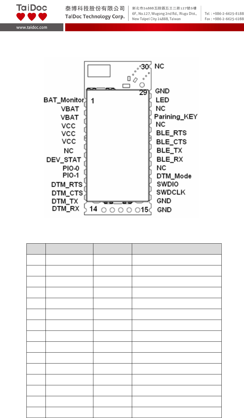
1. Pinout and Terminal Description
Figure 1: Pinout
Pin
Symbol
I/O Type
Description
1 BAT_Monitor I Battery Voltage Monitor
2 VBAT P Power input
3 VBAT P Power input
4 VCC P Power Output
5 VCC P Power Output
6 VCC P Power Output
7 NC NC Not Connect
8 DEV_STAT O Wakeup Device
9 PIO-0 I/O GPIO
10 PIO-1 I/O GPIO
11 DTM_RTS I UART RTS signal (Note.1)
12 DTM_CTS O UART CTS signal (Note.1)
13 DTM_TX O UART TX signal (Note.1)
14 DTM_RX I UART RX signal (Note. 1)
15 GND P GND
A2.1 - 4 of 7
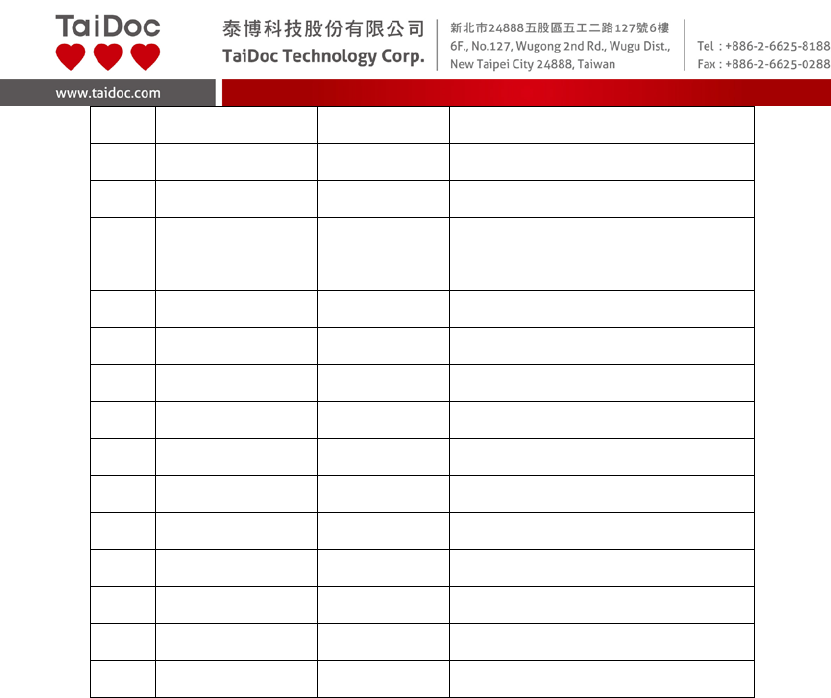
16 GND P GND
17 SWDCLK I JTACK Clock
18 SWDIO I/O JTACK Data
19 DTM_Mode I Set Low to DTM Mode
Set High to BLE Mode
20 NC NC Not Connect
21 BLE_RX I UART RX
22 BLE_TX O UART TX
23 BLE_CTS O UART CTS
24 BLE_RTS I UART RTS
25 NC NC Not Connect
26 Paring_Key I Set Low to Paring Device
27 NC NC Not Connect
28 LED O LED indicator
29 GND P GND
30 NC NC Not Connect
Note.1 DTM is Direct Test Mode。
2. Power supply
The Module accept 3.1V to 4.2V DC voltage input,Power supply should
guarantee good ripple suppression and enough current.
3. Antenna
The module integrates a chip antenna so there’s no need to use antenna on
customer’s PCB.
4. UART interface
This is a standard UART interface for communicating with other serial devices.
The UART interface provides a simple mechanism for communicating with
other serial devices using the RS232 protocol.
The UART CTS and RTS signals can be used to implement RS232 hardware
flow control where both are active low indicators.
Default parameter set is 19200,8,n,1
A2.1 - 5 of 7
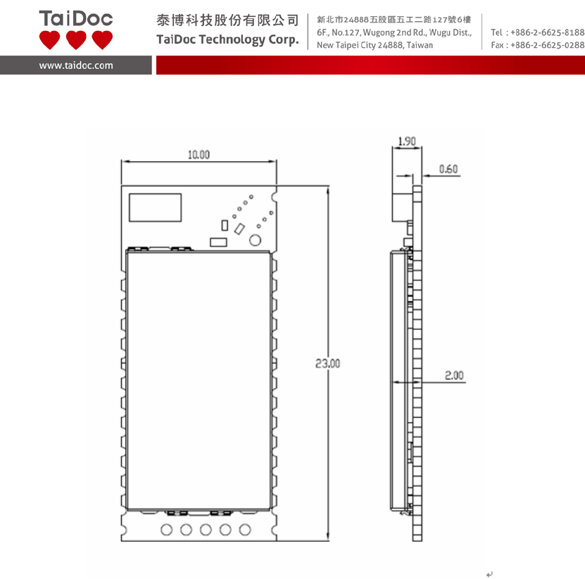
5. Dimension

A2.1 - 6 of 7
FEDERAL COMMUNICATIONS COMMISION (FCC) STATEMENT
15.21
You are cautioned that changes or modifications not expressly approved
by the part responsible for compliance could void the user’s authority to
operate the equipment.
15.105(b)
Federal Communications Commission (FCC) Statement
This equipment has been tested and found to comply with the limits for a Class
B digital device, pursuant to part 15 of the FCC rules. These limits are
designed to provide reasonable protection against harmful interference in a
residential installation. This equipment generates, uses and can radiate radio
frequency energy and, if not installed and used in accordance with the
instructions, may cause harmful interference to radio communications.
However, there is no guarantee that interference will not occur in a particular
installation. If this equipment does cause harmful interference to radio or
television reception, which can be determined by turning the equipment off and
on, the user is encouraged to try to correct the interference by one or more of
the following measures:
-Reorient or relocate the receiving antenna.
-Increase the separation between the equipment and receiver.
-Connect the equipment into an outlet on a circuit different from that to which
the receiver is connected.
-Consult the dealer or an experienced radio/TV technician for help.
This device complies with Part 15 of the FCC Rules. Operation is subject
to the following two conditions:
1) This device may not cause harmful interference and
2) This device must accept any interference received, including interference
that may cause undesired operation of the device.
FCC RF Radiation Exposure Statement:
1. This transmitter must not be co-located or operating in conjunction with any
other antenna or transmitter.
2. This equipment complies with FCC RF radiation exposure limits set forth
for an uncontrolled environment. End users must follow the specific
operating instructions for satisfying RF exposure compliance.
A2.1 - 7 of 7
根據
NCC
低功率電波輻射性電機管理辦法
規定
:
第十二條
經型式認證合格之低功率射頻電機,非經許可,公司、商號或
使用者均不得擅自變更頻率、加大功率或變更原設計之特性及
功能。
第十四條
低功率射頻電機之使用不得影響飛航安全及干擾合法通信;經
發現有干擾現象時,應立即停用,並改善至無干擾時方得繼續
使用。前項合法通信,指依電信法規定作業之無線電通信。
低功率射頻電機須忍受合法通信或工業、科學及醫療用電波輻
射性電機設備之干擾。