TAIYO YUDEN WYSAAVDX7 Wireless LAN Module User Manual Ver 2
Taiyo Yuden Co., Ltd. Wireless LAN Module Ver 2
UserManual.wiki
>
TAIYO YUDEN
>
WYSAAVDX7 User Manual
>
user manual (S)Ver 2
Contents
1.
Users Manual
2.
UM part panel
3.
user manual (M)
4.
user manual (S)Ver 2
user manual (S)Ver 2
Navigation menu
Upload a User Manual
Namespaces
Wiki Guide
HTML
PDF
Info
Views
User Manual
Discussion / Help
Navigation
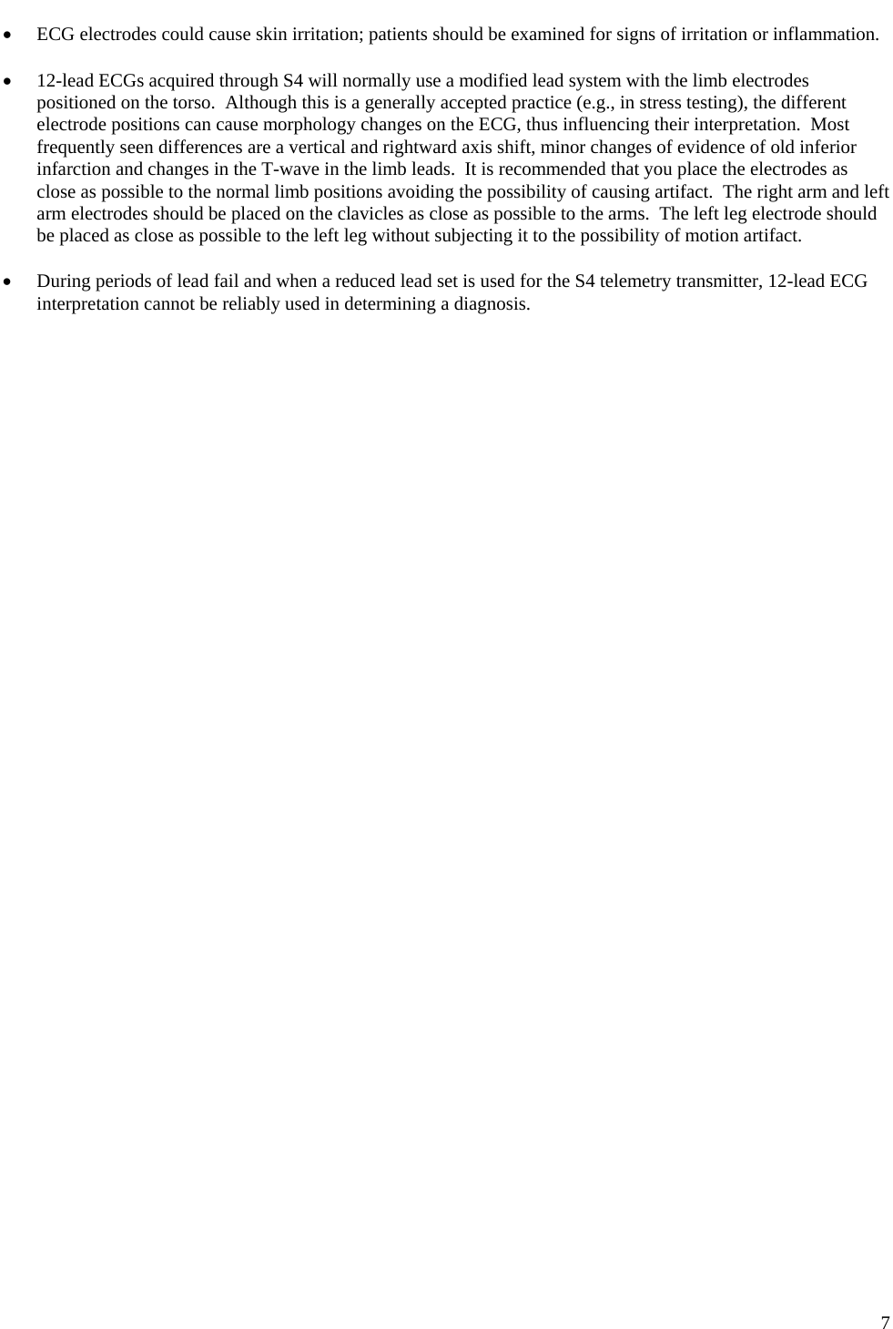
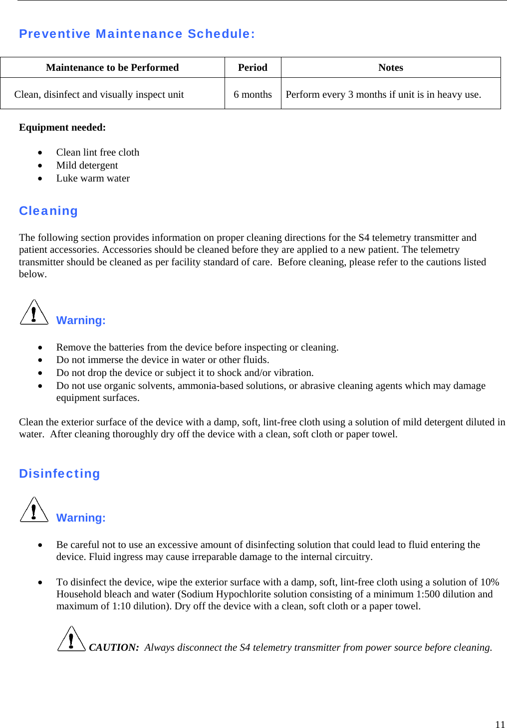
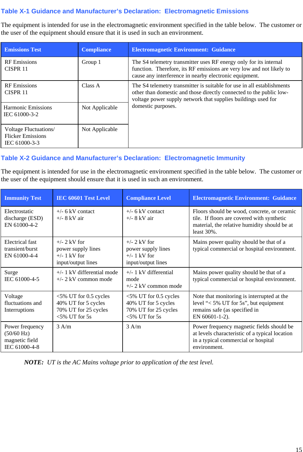
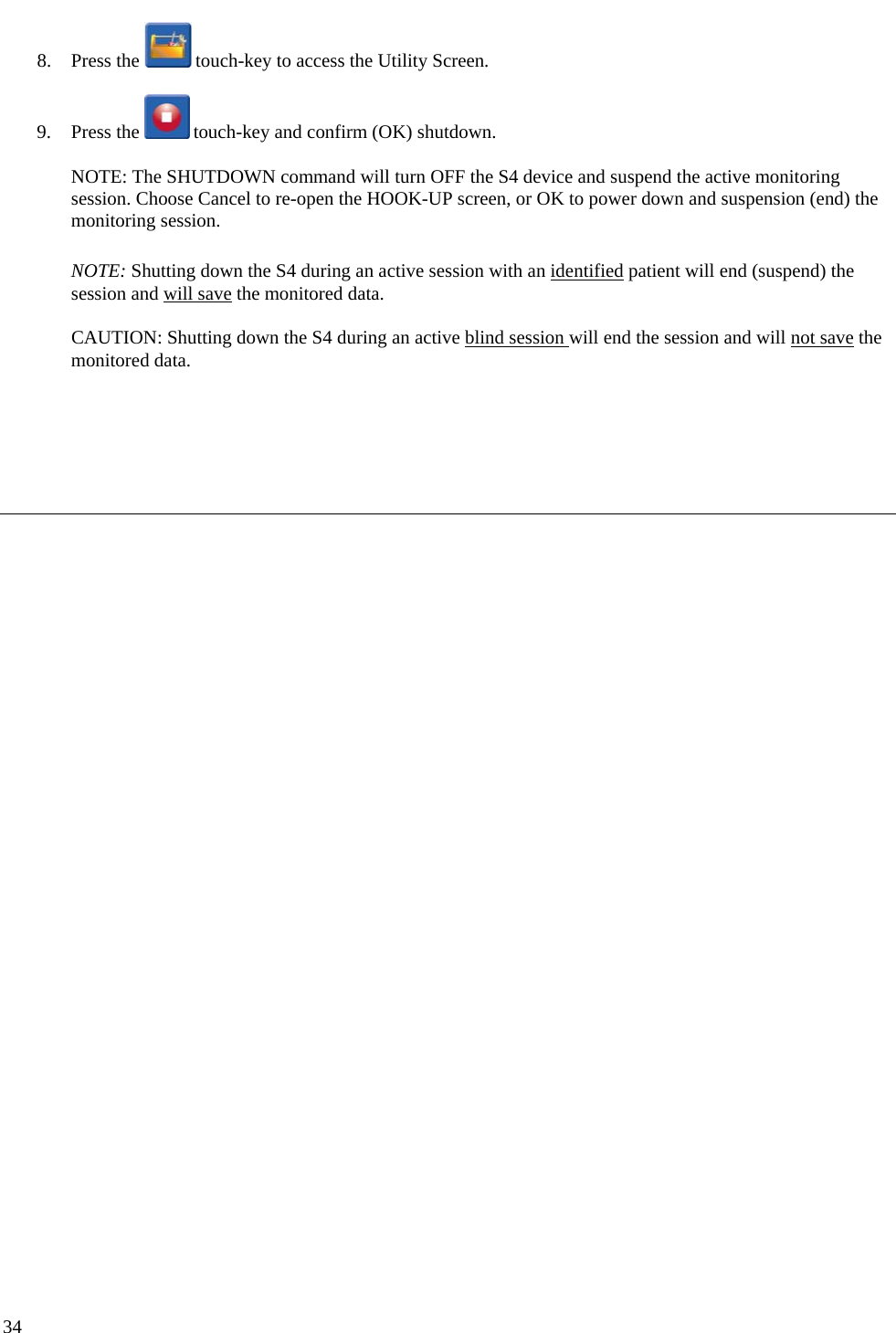
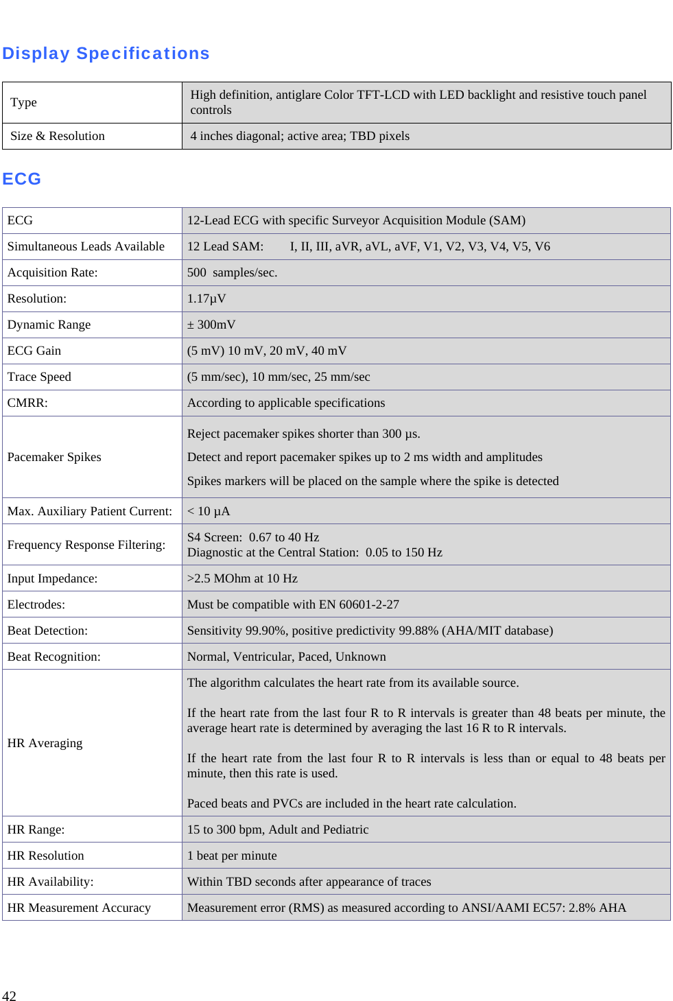
![16 Table X-3 Guidance and Manufacturer’s Declaration: Electromagnetic Immunity The equipment is intended for use in the electromagnetic environment specified in the table below. The customer or the user of the equipment should ensure that it is used in such an environment. Immunity Test IEC 60601 Test Level Compliance Level Electromagnetic Environment: Guidance Conducted RF EN 61000-4-6 3 Vrms 150 kHz to 80 MHz 3 Vrms 150 kHz to 80 MHz Portable and mobile RF communications equipment should be used no closer to any part of the equipment, including cables, than the recommended separation distance calculated from the equation applicable to the frequency of the transmitter. Recommended separation distance d = 1.2 d = 1.2 80 MHz to 800 MHz d = 2.3 800 MHz to 2.5 GHz Where P is the maximum output power rating of the transmitter in watts (W) according to the transmitter manufacturer and d is the recommended separation distance in meters (m). Field strengths from fixed RF transmitters, as determined by an electromagnetic site surveya, should be less than the compliance level in each frequency rangeb. Interference may occur in the vicinity of equipment marked with the following symbol: Radiated RF IEC 61000-4-3 3 V/m 80 MHz to 2.5 GHz 3 V/m 80 MHz to 2.5 GHz a. Field strengths from fixed transmitters, such as base stations for radio (cellular/cordless) telephones and land mobile radios, amateur radios, AM and FM radio broadcast, and TV broadcast cannot be predicted theoretically with accuracy. To assess the electromagnetic environment due to fixed RF transmitters, an electromagnetic site survey should be considered. If the measured field strength in the location in which the equipment is used exceeds the applicable RF compliance level above, the equipment should be observed to verify normal operation. If abnormal performance is observed, additional measures may be necessary, such as reorienting or relocating the equipment. b. Over the frequency range 150 kHz to 80 MHz, field strengths should be less than [3] V/m.](https://usermanual.wiki/TAIYO-YUDEN/WYSAAVDX7.user-manual-S-Ver-2/User-Guide-2124404-Page-20.png)
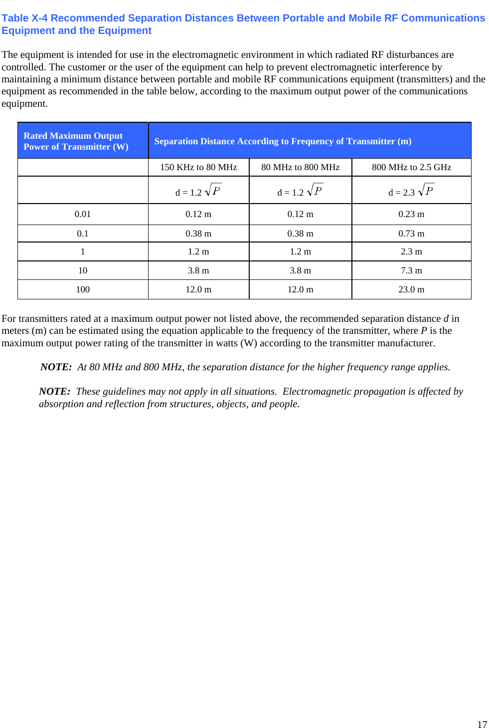
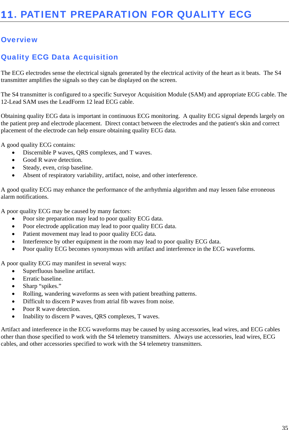
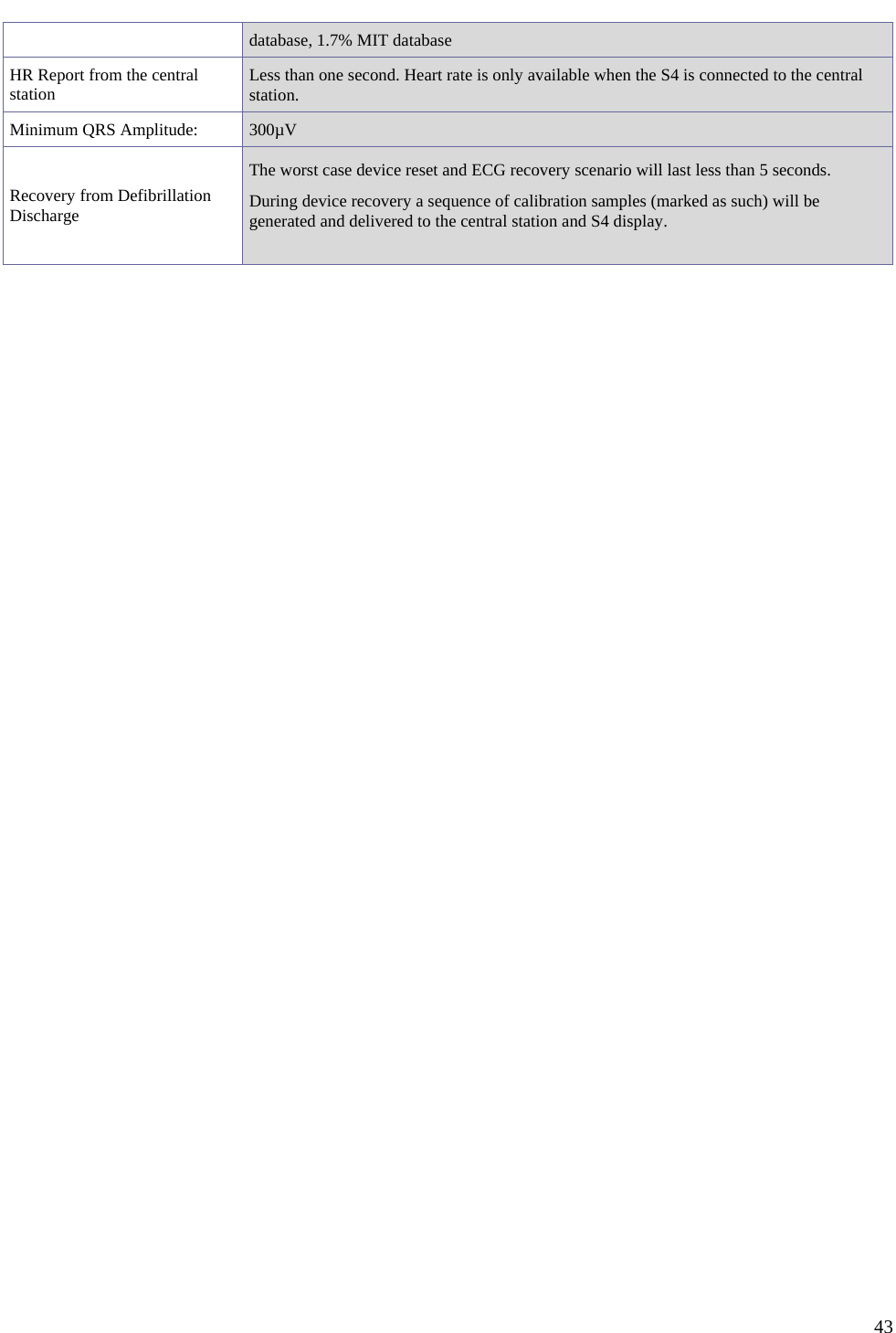
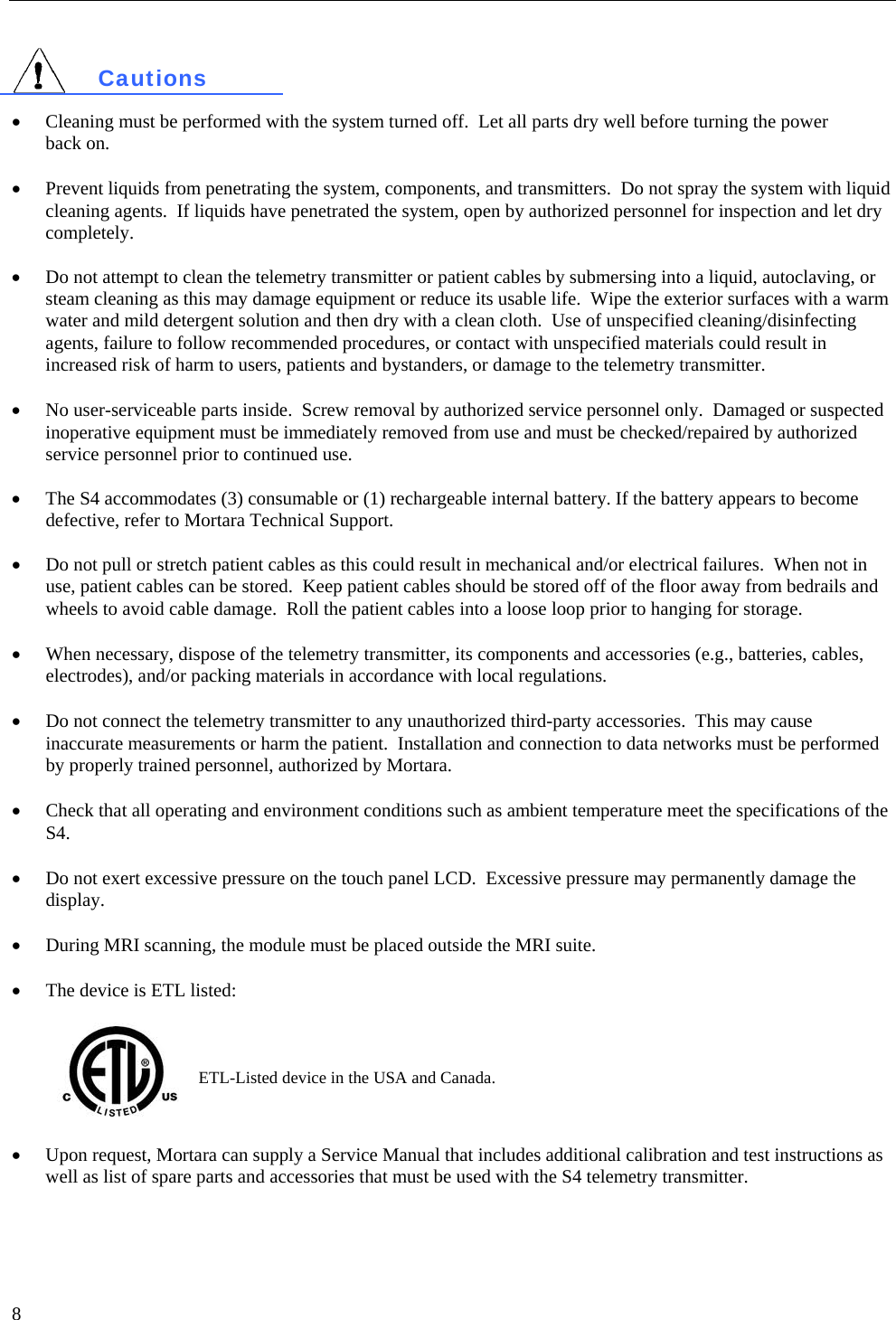
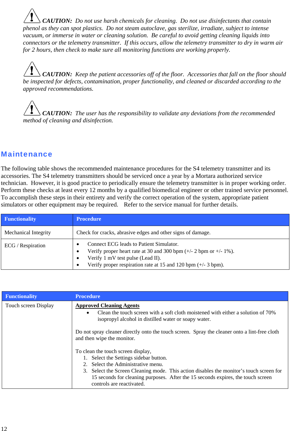
![18 USA and Canada Radio Regulations USA (FCC) This device is equipped with Transmitter Module with FCC ID:RYYWYSAAVDX7 This device complies with part 15 of the FCC Rules. Operation is subject to the following two conditions: (1) This device may not cause harmful interference, and (2) this device must accept any interference received, including interference that may cause undesired operation. [Caution] Changes or modifications not expressly approved by the party responsible for compliance could void the user’s authority to operate the equipment. This device with transmitter module has been tested to SAR and complies to FCC exposure requirements for portable devices. SAR testing has been done at a distance of 10mm from the face and 0mm from the body. Canada (IC) This device is equipped with Transmitter Module with IC:4389B-WYSAAVDX7. This device complies with Industry Canada license-exempt RSS standard(s). Operation is subject to the following two conditions: (1) this device may not cause interference, and (2) this device must accept any interference, including interference that may cause undesired operation of the device." This device with transmitter module has been tested to SAR and complies to IC exposure requirements for portable devices. SAR testing has been done at a distance of 10mm from the face and 0mm from the body. (French) Cet appareil est équipé d'un module émetteur avec marque IC:4389B-WYSAAVDX7 L’appareil conforme aux CNR d'Industrie Canada applicables aux appareils radio exempts de licence. L'exploitation est autorisée aux deux conditions suivantes: (1) l'appareil ne doit pas produire de brouillage, et (2) l'appareil doit accepter tout brouillage radioélectrique subi, même si le brouillage est susceptible d'en compromettre le fonctionnement. Cet appareil avec module émetteur a été testé pour les taux d'absorption spécifique (DAS) et est conforme aux normes d'exposition d'IC pour les appareils portables. Tests de DAS ont été réalisés à une distance de 10mm du visage et du corps 0mm. This device is defibrillator protected in compliance with AAMI standards and IEC 60601-2-25.](https://usermanual.wiki/TAIYO-YUDEN/WYSAAVDX7.user-manual-S-Ver-2/User-Guide-2124404-Page-22.png)
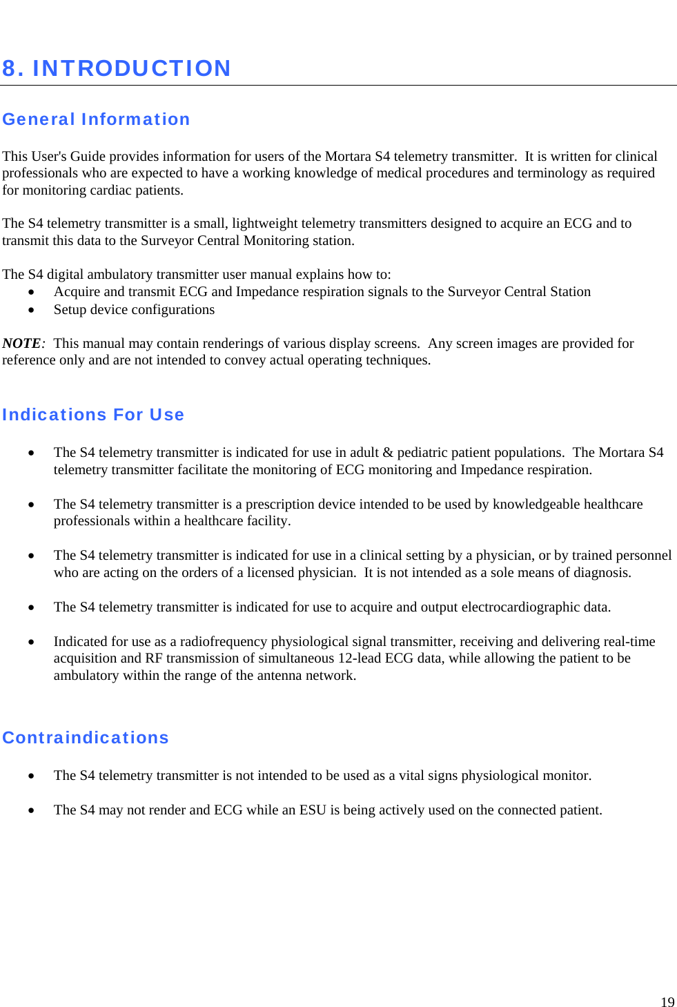
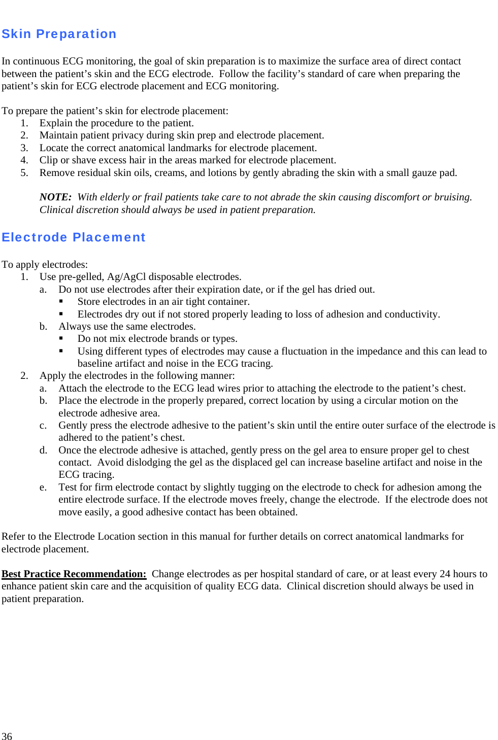
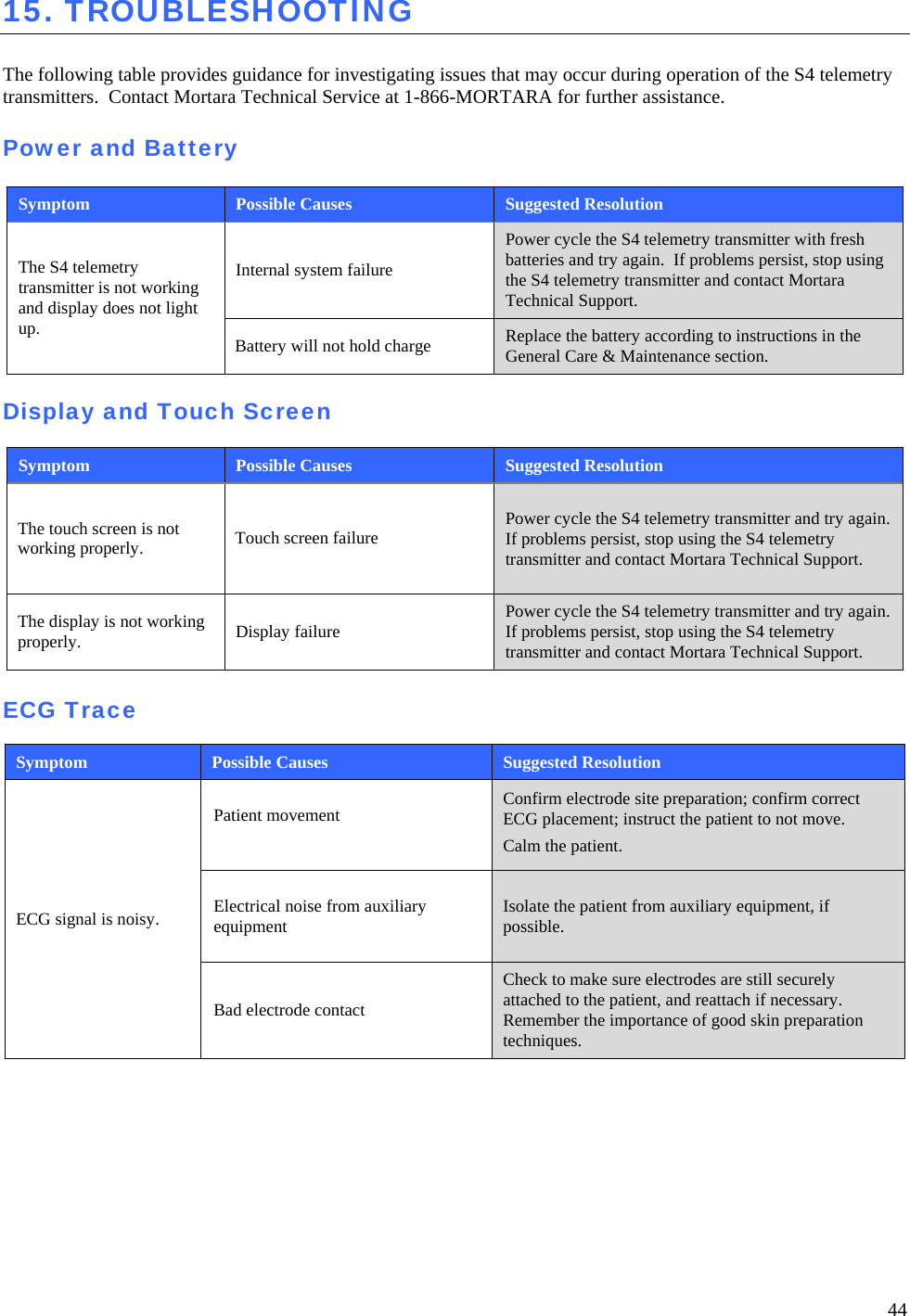
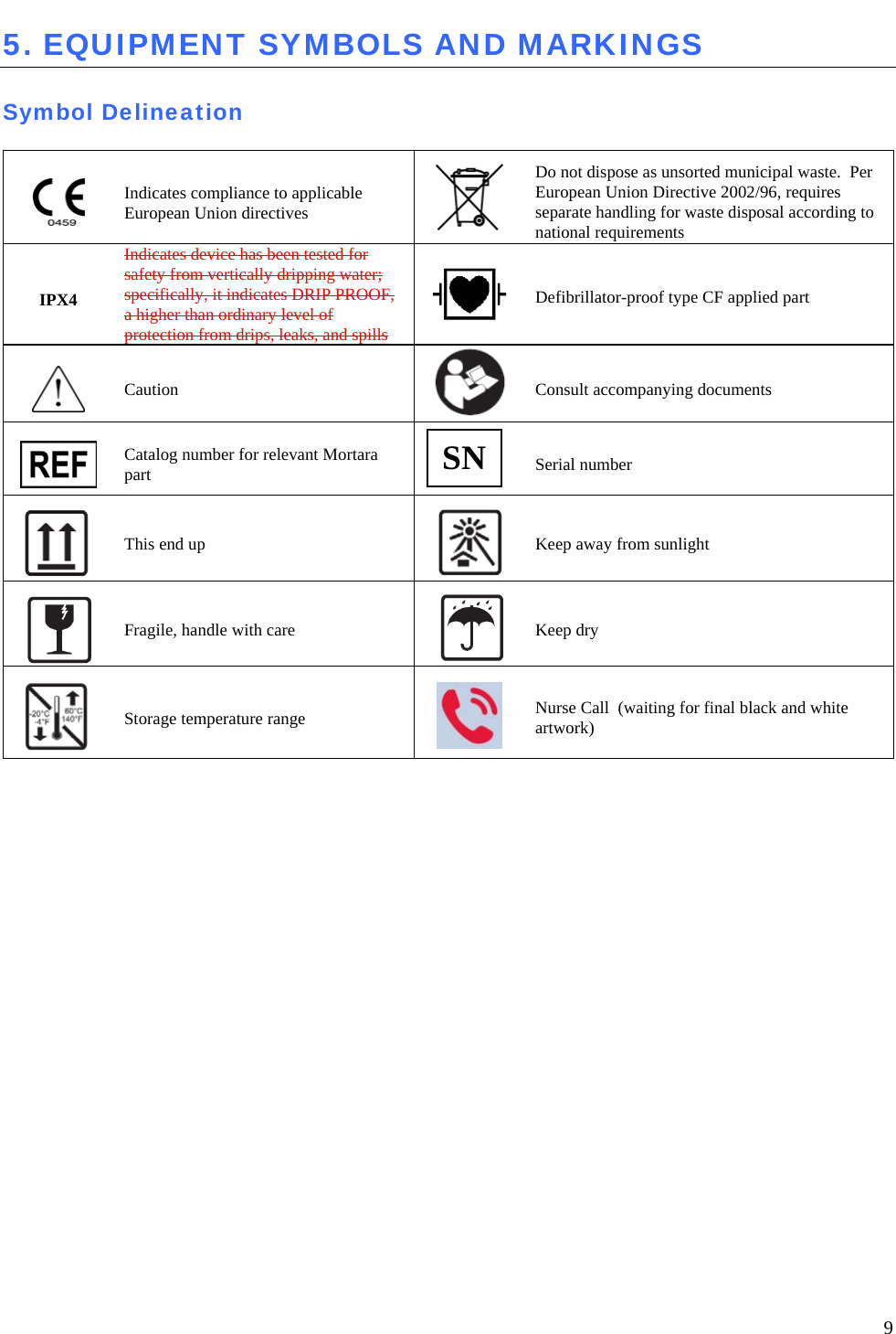
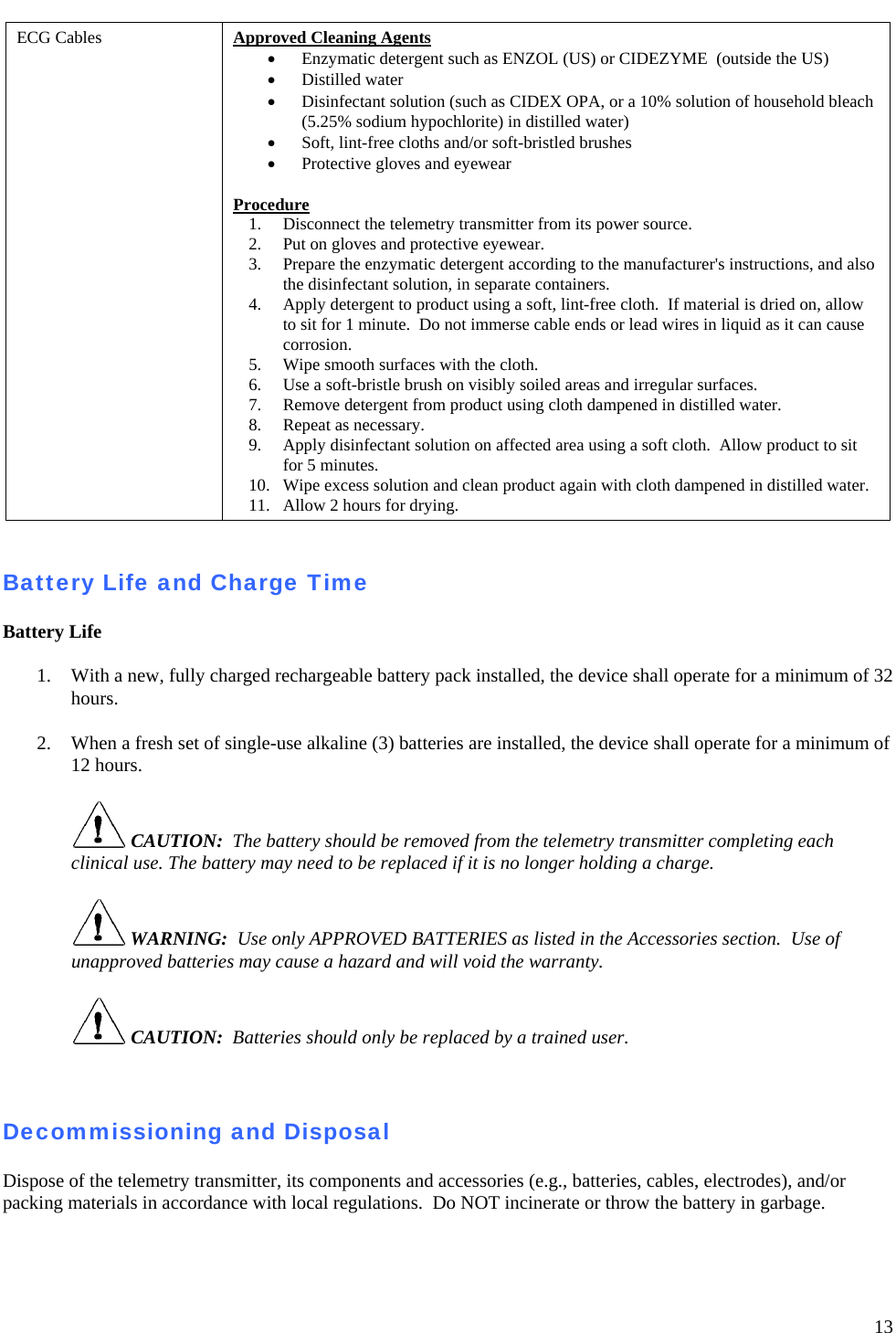
![24 Resume Operation After Shutdown • Pressing the Nurse Call button to enter the Resume Operation screen. • Pressing the [CANCEL] touch-key will cancel the Nurse Call signal destined for the central station, and instead enter the HOOK-UP screen. • Not pressing the [CANCEL] touch-key within 20 seconds will transmit the Nurse Call signal to the central station and the display will dim to black. Entering a Passcode • Power the S4 ON by loading the battery or by resuming operation (see above). The LED indicators will flash. • Within a few seconds the HOOK-UP screen will appear. • Pressing the TOOLBOX touch-key will enter the Unlock Screen. This screen is displayed whenever the operator tries to perform a protected action such as entering in the Utility screen before unlocking S4 with the correct Passcode. • Enter the correct (preset) passcode using the keypad. Then press OK or one of the following touch-keys: o OK (will verify the entered code against the preset valid passcode) o CL (will clear the entered code) o CANCEL (will cancel the requested action) Connecting S4 to the Surveyor Central Station • Connection of the S4 transmitter to the Surveyor Central Station is automatic on power ON of the S4. The LED located below the WIFI icon indicates that the S4 is connected to the central station when the LED is illuminated, and flashes when the S4 is searching for WiFi connection. NOTE: Refer to the service manual for further details on central station networking.](https://usermanual.wiki/TAIYO-YUDEN/WYSAAVDX7.user-manual-S-Ver-2/User-Guide-2124404-Page-28.png)


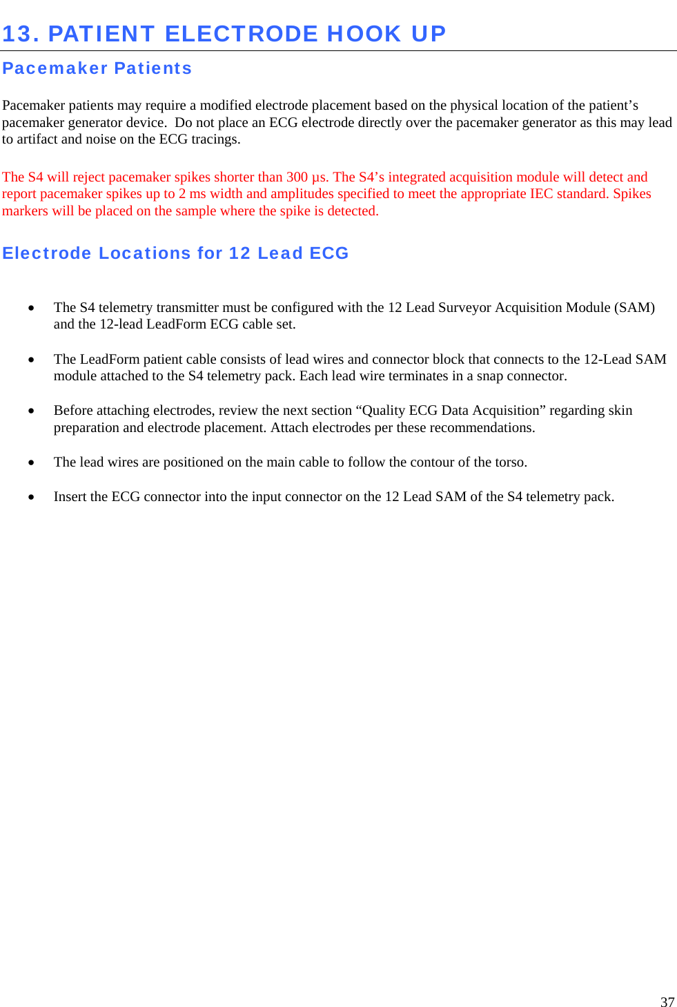
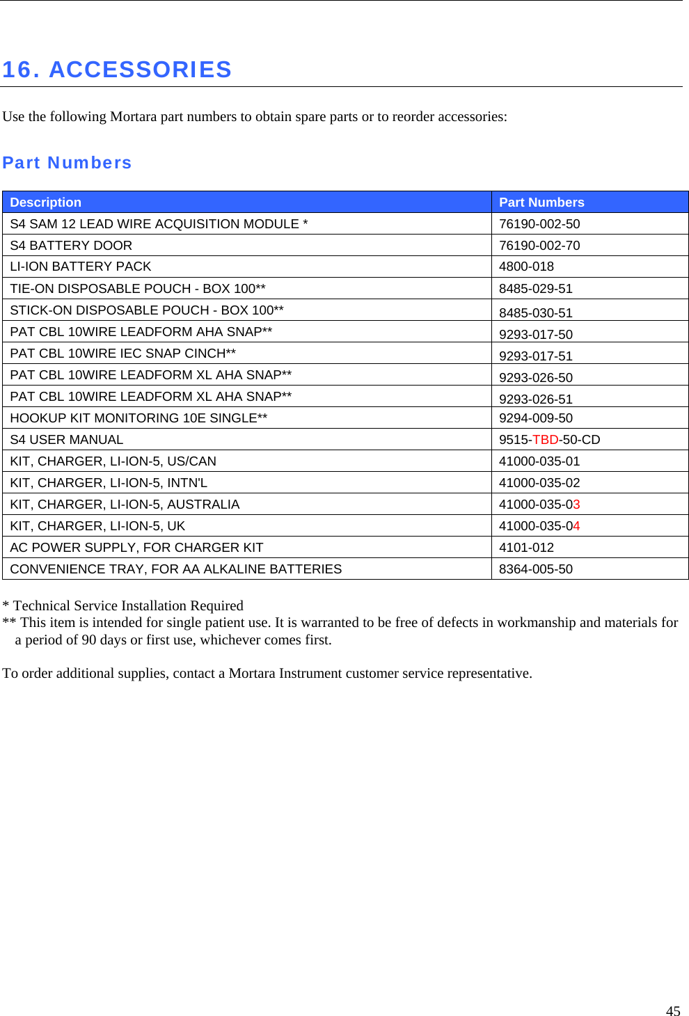
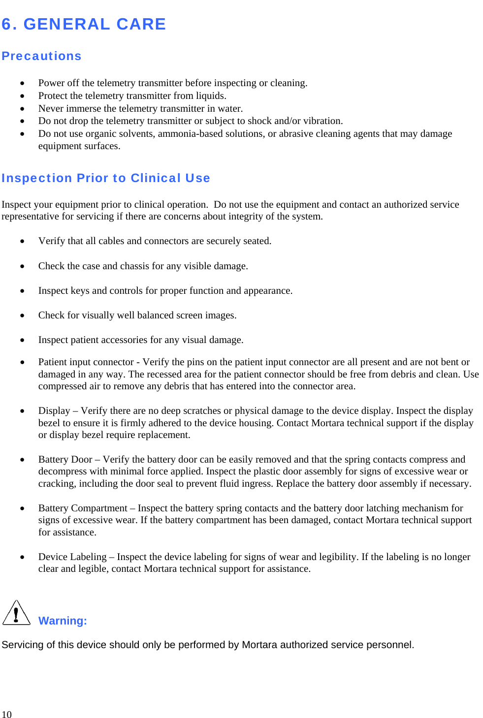
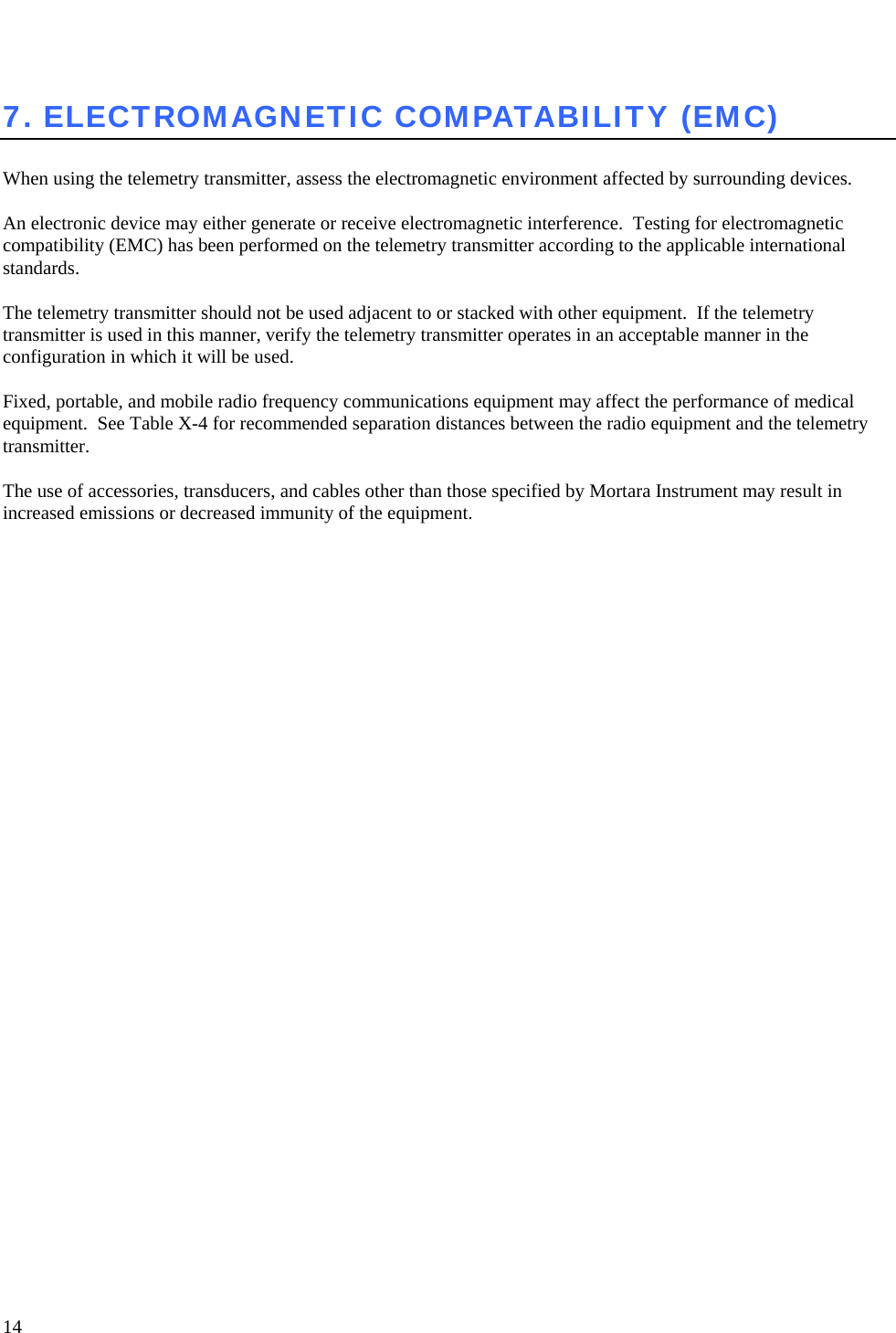
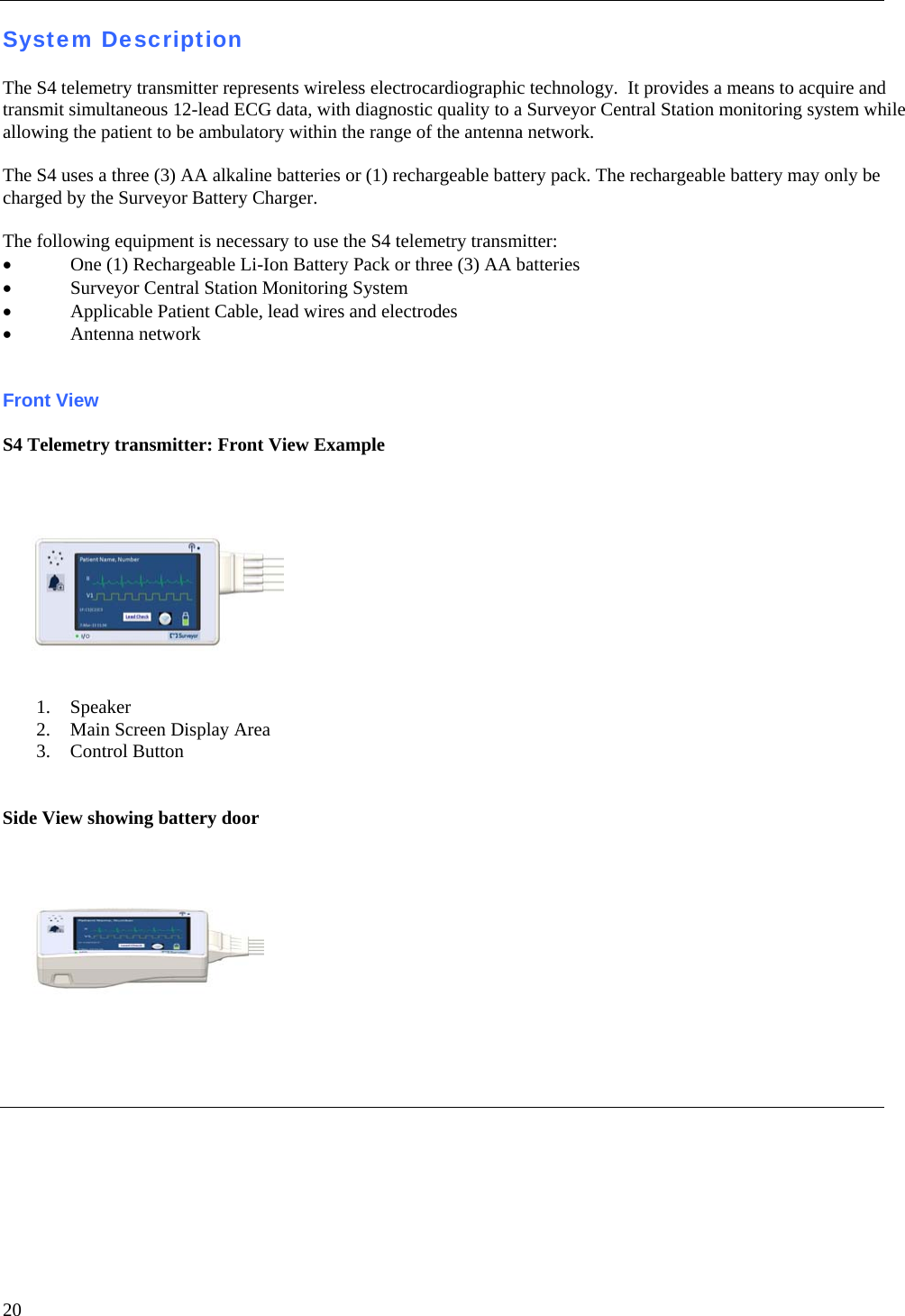
![33 10. STARTING A MONITORING SESSION Starting a Monitoring Session 1. Insert the battery into the S4 to turn ON the device. 2. Press the touch-key to enter the UNLOCK Screen. 3. Enter the Passcode to unlock the S4 device. 4. Press the touch-key. Attach the electrodes and lead wires to the patient. NOTE: Using the screen’s Torso image, visualize the proper electrode placement locations and attach electrodes and lead wires to the patient to achieve all green indications, to assure a high quality signal. 5. Press the touch-key to enter the Start Session screen. NOTE: The Start Session screen allows the operator to start a monitoring session. The top of the screen will display the Information Header. A dropdown menu will be populated with the list of profiles currently available on the central station. 6. Select the patient o Press the SAME touch-key to restart the previous monitoring session preserving the patient record last associated with the monitoring slot. The touch-key is grey (disabled) if there is no patient record associated with that central station slot. Or… o Press the NEW touch-key to start a new monitoring session where no patient demographics yet entered (blind session). The session will use the profile currently selected in the dropdown menu. 7. To end a session, first activate the S4 operation capability: a) Press the button to activate the screen. b) Press the [ABORT] touch-key within 20 seconds, to cancel the Nurse Call signal and resume operation of the S4 device.](https://usermanual.wiki/TAIYO-YUDEN/WYSAAVDX7.user-manual-S-Ver-2/User-Guide-2124404-Page-37.png)