TAIYO YUDEN WYSAAVDX7 Wireless LAN Module User Manual Ver 2
Taiyo Yuden Co., Ltd. Wireless LAN Module Ver 2
Contents
- 1. Users Manual
- 2. UM part panel
- 3. user manual (M)
- 4. user manual (S)Ver 2
user manual (S)Ver 2
TABLE OF CONTENTS
REF 9515-TBD-50-ENG Rev E
S4
12 LEAD TELEMETRY TRANSMITTER
USER MANUAL
Manufactured by Mortara Instrument, Inc., Milwaukee, Wisconsin U.S.A.
CAUTION: Federal law restricts this device to sale by or on the order of a physician.

Copyright © 2013
by Mortara Instrument, Inc.
7865 N. 86th Street
Milwaukee, Wisconsin 53224
This document contains confidential information that belongs to Mortara Instrument, Inc. No part of this document
may be transmitted, reproduced, used, or disclosed outside of the receiving organization without the express written
consent of Mortara Instrument, Inc.
Mortara is a registered trademark of Mortara Instrument, Inc. S4™ and VERITAS™ are trademarks of Mortara
Instrument, Inc.
All other trademarks and registered trademarks are the property of their respective owners.

i
TABLE OF CONTENTS
1. GENERAL STATEMENTS ....................................................................................................................... 1
TECHNICALSUPPORTANDSERVICE.....................................................................................................................................1
2. NOTICES .................................................................................................................................................. 2
MANUFACTURER’SRESPONSIBILITY....................................................................................................................................2
RESPONSIBILITYOFTHECUSTOMER....................................................................................................................................2
EQUIPMENTIDENTIFICATION.............................................................................................................................................2
COPYRIGHTANDTRADEMARKNOTICES...............................................................................................................................2
OTHERIMPORTANTINFORMATION.....................................................................................................................................2
3. WARRANTY INFORMATION ................................................................................................................... 3
4. USER SAFETY INFORMATION .............................................................................................................. 4
SAFETYREGULATIONS......................................................................................................................................................4
WARNINGS....................................................................................................................................................................4
Power Warnings
............................................................................................................................................5
Accessories, Cables, and External Connections Warnings
...................................................6
Use with Electro Surgery Devices Warnings
.................................................................................6
ECG Warnings
................................................................................................................................................6
CAUTIONS.....................................................................................................................................................................8
5. EQUIPMENT SYMBOLS AND MARKINGS ............................................................................................ 9
SYMBOLDELINEATION.....................................................................................................................................................9
PRECAUTIONS..............................................................................................................................................................10
INSPECTIONPRIORTOCLINICALUSE.................................................................................................................................10
CLEANING...................................................................................................................................................................11
MAINTENANCE.............................................................................................................................................................12
BATTERYLIFEANDCHARGETIME.....................................................................................................................................13
DECOMMISSIONINGANDDISPOSAL..................................................................................................................................13
7. ELECTROMAGNETIC COMPATABILITY (EMC) ................................................................................. 14
USAANDCANADARADIOREGULATIONS..........................................................................................................................18
8. INTRODUCTION ..................................................................................................................................... 19
GENERALINFORMATION................................................................................................................................................19
INDICATIONSFORUSE...................................................................................................................................................19
CONTRAINDICATIONS.....................................................................................................................................................19
SYSTEMDESCRIPTION....................................................................................................................................................20
FrontView............................................................................................................................................................20
CARRYING POUCH ................................................................................................................................... 21
TIE-ON POUCH .......................................................................................................................................... 21
STICK-ON POUCH 9. UNPACKING AND SET UP ................................................................................... 21
9. UNPACKING AND SET UP ................................................................................................................... 22
CHECKINGCONTENTS....................................................................................................................................................22

TABLE OF CONTENTS
ii
10. OPERATION ......................................................................................................................................... 23
TURNINGTHES4ON.....................................................................................................................................................23
CONNECTINGS4TOTHESURVEYORCENTRALSTATION........................................................................................................24
10. STARTING A MONITORING SESSION .............................................................................................. 33
11. PATIENT PREPARATION FOR QUALITY ECG ................................................................................. 35
OVERVIEW..................................................................................................................................................................35
QUALITYECGDATAACQUISITION...................................................................................................................................35
SKINPREPARATION.......................................................................................................................................................36
ELECTRODEPLACEMENT.................................................................................................................................................36
13. PATIENT ELECTRODE HOOK UP...................................................................................................... 37
Pacemaker Patients
.................................................................................................................................37
ELECTRODELOCATIONSFOR12LEADECG........................................................................................................................37
Using the LeadForm 12-lead Cable
..................................................................................................39
CHECKINGECGELECTRODEANDLEADWIRESIGNALQUALITY..............................................................................................40
14. PRODUCT SPECIFICATIONS ............................................................................................................. 41
GENERALSPECIFICATIONS..............................................................................................................................................41
ENVIRONMENTALCONDITIONS........................................................................................................................................41
POWERREQUIREMENTS&BATTERY.................................................................................................................................41
DISPLAYSPECIFICATIONS................................................................................................................................................42
ECG..........................................................................................................................................................................42
15. TROUBLESHOOTING ......................................................................................................................... 44
POWERANDBATTERY....................................................................................................................................................44
DISPLAYANDTOUCHSCREEN..........................................................................................................................................44
ECGTRACE.................................................................................................................................................................44
16. ACCESSORIES .................................................................................................................................... 45
* TECHNICAL SERVICE INSTALLATION REQUIRED....................................................................................................45
** THIS ITEM IS INTENDED FOR SINGLE PATIENT USE. IT IS WARRANTED TO BE FREE OF DEFECTS IN WORKMANSHIP
AND MATERIALS FOR A PERIOD OF 90 DAYS OR FIRST USE, WHICHEVER COMES FIRST...............................................45
17. APPLICABLE STANDARDS ............................................................................................................... 46

1
1. GENERAL STATEMENTS
Technical Support and Service
Headquarters
Mortara Instrument, Inc.
7865 North 86th Street
Milwaukee, WI 53224
U.S.A.
Tel: 414.354.1600
Tel: 800.231.7437
Fax: 414.354.4760
Internet: http://www.mortara.com
European Union
Representative
Mortara Rangoni Europe, Srl
(European Headquarters)
Via Cimarosa 103/105
40033 Casalecchio di Reno (BO)
Italy
Tel: +39.051.298.7811
Fax: +39.051.613.3582
Service/Technical
Support Group
Mortara Instrument, Inc.
7865 North 86th Street
Milwaukee, WI 53224
U.S.A.
Tel: 414.354.1600
Service: 888.MORTARA
(888.667.8272)
Fax: 414.354.4760
E-mail: techsupport@mortara.com
24-hour Technical Support
Same-day Shipment of Replacement Parts
Biomedical Training Classes
Extended Warranties/Service Contracts
Sales Support/
Supplies & Accessories
Mortara Instrument, Inc.
7865 North 86th Street
Milwaukee, WI 53224
U.S.A.
Tel: 414.354.1600
Fax: 414.354.4760
E-mail: sales@mortara.com
Mortara Instrument Germany
Bonifaciusring 15
45309 Essen
Germany
Tel: +49.201.18 55 69 70
Fax: +49.201.18 55 69 77
Mortara Instrument Netherlands
Postbus 324
5680 AH Best
Industrieweg 160b
5683 CG Best
Netherlands
Tel: +31.499.377310
Fax: +31.499.377908
Mortara Instrument Australia
PO Box 7568
Baulkham Hills NSW 2153
Unit 28, 9 Hoyle Avenue
Castle Hill NSW 2154
Australia
Tel: +61 2 8070 9303
Fax: +61 2 9899 9478
Mortara Dolby UK Ltd.
Units 11 & 12, Scion House
Stirling University Innovation Park
Stirling FK9 4NF
Scotland
Tel: +44.1786.444980
Fax: +44.1786.446630

2
2. NOTICES
Manufacturer’s Responsibility
Mortara Instrument, Inc. is responsible for the effects on safety and performance of the telemetry transmitter, as
indicated by the label, only if article 2 of 93/42/EEC directive is applied, in particular:
• WARNING: System installation and assembly operations, extensions, readjustments, modifications or
repairs are carried out by personnel authorized by Mortara Instrument, Inc. only.
• The telemetry transmitter is used in accordance with the instructions for use.
• The telemetry transmitter is correctly maintained according to the standards authorized by Mortara Instrument,
Inc. using original spare parts.
• The telemetry transmitter is used with original accessories and supplies that are in compliance with the standard
specifications described in this manual.
• The electrical installation of the relevant room complies with the requirements of appropriate regulations.
Responsibility of the Customer
The user of this telemetry transmitter is responsible for ensuring the implementation of a satisfactory maintenance
schedule. Failure to do so may cause undue failure and possible health hazards. This manual must be kept in a safe
place to prevent its deterioration and/or alteration. The user and Mortara Instrument, Inc. authorized personnel must
have access to this manual at any time. The user of this telemetry transmitter must periodically check the
accessories, their functionality and integrity.
Equipment Identification
Mortara Instrument, Inc. equipment is identified by a serial and reference number on the back of the telemetry
transmitter. Care should be taken so that these numbers are not defaced.
Copyright and Trademark Notices
This document contains information that is protected by copyright. All rights are reserved. No part of this
document may be photocopied, reproduced, or translated into another language without prior written consent of
Mortara Instrument, Inc.
Other Important Information
The information in this document is subject to change without notice.
Mortara Instrument, Inc. makes no warranty of any kind with regard to this material including, but not limited to,
implied warranties of merchantability and fitness for a particular purpose. Mortara Instrument, Inc. assumes no
responsibility for any errors or omissions that may appear in this document. Mortara Instrument, Inc. makes no
commitment to update or to keep current the information contained in this document.

3
3. WARRANTY INFORMATION
MORTARA INSTRUMENT, INC. (hereafter referred to as “Mortara”) warrants that components within Mortara
products (hereafter referred to as “Product/s”) will be free from defects in workmanship and materials for the
number of years specified on documentation accompanying the product, or previously agreed to by the purchaser
and Mortara, or if not otherwise noted, for a period of twelve (12) months from the date of shipment.
Consumable, disposable or single use products such are warranted to be free from defects in workmanship and
materials for a period of 90 days from the date of shipment or the date of first use, whichever is sooner.
Reusable product such as, but not limited to, BATTERIES, PATIENT CABLES, LEAD WIRES, MAGNETIC
STORAGE MEDIUMS, CARRY CASES or MOUNTS, are warranted to be free from defects in workmanship and
materials for a period of 90 days. This warranty does not apply to damage to the Product/s caused by any or all of
the following circumstances or conditions:
a) Freight damage;
b) Supplies, accessories and internal parts NOT approved by Mortara;
c) Misapplication, misuse, abuse, and/or failure to follow the Product/s instruction sheets and/or information
guides;
d) Accident;
e) A disaster affecting the Product/s;
f) Alterations and/or modifications to the Product/s not authorized by Mortara;
g) Other events outside of Mortara’s reasonable control or not arising under normal operating conditions.
THE REMEDY UNDER THIS WARRANTY IS LIMITED TO THE REPAIR OR REPLACEMENT WITHOUT
CHARGE FOR LABOR OR MATERIALS, OR ANY PRODUCT/S FOUND UPON EXAMINATION BY
MORTARA TO HAVE BEEN DEFECTIVE. This remedy shall be conditioned upon receipt of notice by Mortara
of any alleged defects promptly after discovery thereof within the warranty period. Mortara’s obligations under the
foregoing warranty will further be conditioned upon the assumption by the purchaser of the Product/s (i) of all
carrier charges with respect to any Product/s returned to Mortara’s principal place or any other place as specifically
designated by Mortara or an authorized distributor or representative of Mortara, and (ii) all risk of loss in transit. It
is expressly agreed that the liability of Mortara is limited and that Mortara does not function as an insurer. A
purchaser of a Product/s, by its acceptance and purchase thereof, acknowledges and agrees that Mortara is not liable
for loss, harm, or damage due directly or indirectly to an occurrence or consequence there from relating to the
Product/s. If Mortara should be found liable to anyone under any theory (except the expressed warranty set forth
herein) for loss, harm, or damage, the liability of Mortara shall be limited to the lesser of the actual loss, harm, or
damage, or the original purchase price of the Product/s when sold.
EXCEPT AS SET FORTH HEREIN WITH RESPECT TO REIMBURSEMENT OF LABOR CHARGES, A
PURCHASER’S SOLE EXCLUSIVE REMEDY AGAINST MORTARA FOR CLAIMS RELATING TO THE
PRODUCT/S FOR ANY AND ALL LOSSES AND DAMAGES RESULTING FROM ANY CAUSE SHALL BE
THE REPAIR OR REPLACEMENT OF DEFECTIVE PRODUCT/S TO THE EXTENT THAT THE DEFECT IS
NOTICED AND MORTARA IS NOTIFIED WITHIN THE WARRANTY PERIOD. IN NO EVENT,
INCLUDING THE CLAIM FOR NEGLIGENCE, SHALL MORTARA BE LIABLE FOR INCIDENTAL,
SPECIAL, OR CONSEQUENTIAL DAMAGES, OR FOR ANY OTHER LOSS, DAMAGE, OR EXPENSE OF
ANY KIND, INCLUDING LOSS OF PROFITS, WHETHER UNDER TORT, NEGLIGENCE OR STRICT
LIABILITY THEORIES OF LAW, OR OTHERWISE. THIS WARRANTY IS EXPRESSLY IN LIEU OF ANY
OTHER WARRANTIES, EXPRESS OR IMPLIED, INCLUDING, BUT NOT LIMITED TO THE IMPLIED
WARRANTY OF MERCHANTABILITY AND THE WARRANTY OF FITNESS FOR A PARTICULAR
PURPOSE.

4
4. USER SAFETY INFORMATION
Warning: Means there is the possibility of personal injury to you or others.
Caution: Means there is the possibility of damage to the telemetry transmitter.
Note: Provides information to further assist in the use of the telemetry transmitter.
NOTE: This manual may contain screen shots and pictures. Any screen shots and pictures are provided
for reference only and are not intended to convey actual operating techniques. Consult the actual screen
in the host language for specific wording.
Safety Regulations
• S4 is a medical telemetry transmitter.
• S4 and its accessories are labeled, according to applicable standards.
• S4 with all accessories that have a physical or logical connection with it, forms part of a Medical Electrical
System.
• S4 complies with various safety and performance regulations as mentioned in this manual (Applied Standards).
Warnings
• This manual gives important information about the use and safety of this telemetry transmitter. Deviating from
operating procedures, misuse or misapplication of the telemetry transmitter, or ignoring specifications and
recommendations could result in increased risk of harm to users, patients and bystanders, or damage to the
telemetry transmitter.
• Users are expected to be licensed clinical professionals knowledgeable about medical procedures and patient
care, and adequately trained in the use of this telemetry transmitter. Telemetry transmitter captures and presents
data reflecting a patient’s physiological condition that when reviewed by a trained physician or clinician can be
useful in determining a diagnosis; however, the data should not be used as a sole means for determining a
patient’s diagnosis.
• Before attempting to use this device for clinical applications, the operator must read and understand the
contents of the user manual and other accompanying documents. Inadequate knowledge or training could
result in increased risk of harm to users, patients and bystanders, or damage to the telemetry transmitter.
Contact Mortara Technical Service for additional training options.
• Operation of the equipment beyond its specified ranges, or beyond normal physiological conditions of human
subjects, may cause inaccurate results.
• To ensure the safety of both the patient and the device, 1.5 meters (5’) of open area should surround the patient.
• A possible explosion hazard exists. Do not use the device in the presence of a flammable anesthetic mixture.
Do not mount any part of the device closer than 25 cm from outlets of flammable gases, including oxygen.
• For proper operation and the safety of users or patients and bystanders, equipment and accessories must be
connected only as described in this manual.

5
• Repairs and modification must be made by authorized and trained technical personnel. Unauthorized
modifications and repairs will void the S4 warranty and may pose a danger to patients and users.
• If additional devices beyond S4 are connected to the patient, leakage currents through the patient might add up
and should be accounted for.
• The S4, as all medical equipment or systems, needs special precautions regarding EMC and needs to be
installed and put into service according to the EMC information provided in the installation procedure in order
to obtain a sufficient degree of immunity as well as not to create disturbance to other equipment. Refer to the
specific EMC instructions in this manual.
• The quality of the signal produced by the device may be adversely affected by the use of other medical
equipment, including but not limited to electrosurgery and ultrasound machines. Do not use the system in the
presence of imaging equipment such as magnetic resonance imaging (MRI) and tomography systems.
Simultaneous operation may damage the device or lead to erroneous results.
• Portable and mobile RF communications equipment may affect medical electrical equipment or systems as
well as the S4 and its accessories. Do not operate the S4 near high frequency emissions (e.g. microwaves).
• Various alarm conditions arising at the Central Station require operator to adjust alarm configurations
individualized according to patient condition and demographics.
• A telemetry transmitter is not intended to replace clinical assessments. It is important that a qualified individual
regularly supervise the patient.
Power Warnings
• Only use the Mortara-provided external battery charger and adapter with the S4. Ensure that the power adapter
is connected to a properly grounded power terminal and the electrical installation complies with local safety
requirements for the environment where it is used.
• To ensure that electrical safety is maintained during operation from AC power, the S4 external power adapter
must be plugged into a hospital-grade outlet.
• Regularly check all cables for damage and proper connection. Do not use equipment with a damaged cable.
• The S4 contains an internal battery. The following precautions should be taken regarding the battery:
o Do not immerse the device in water.
o Do not heat or throw the device in fire.
o Do not leave the in conditions over 60 ºC or in a heated car.
o Do not attempt to crush or drop the device.
o Only use the approved batteries with the S4 monitor.
o Follow the instructions in the disposal section of this manual when the S4 is taken out of service.
• The S4 battery must be initially fully charged prior to use.
• The S4 screen initially turns on when batteries are installed, remove the S4 from service and contact Mortara
Technical Support if the screen does not activate when new or fully charged batteries are initially installed.
• Always remove the batteries after completing operating the telemetry transmitter. Always place rechargeable
batteries in the battery charger when not in use. This ensures that the batteries are recharged for the next time
the telemetry transmitter is operated.

6
Accessories, Cables, and External Connections Warnings
• The S4 telemetry transmitter is designed to meet applicable specifications when using Mortara-approved patient
cables and accessories. Use of non-approved cables and accessories may result in reduced performance and
may pose possible patient and user safety concerns.
• It is the user’s responsibility to use only approved supplies, accessories and internal parts available through
Mortara Instrument, Inc. Product performance and patient safety require the use of supplies, accessories and
internal parts that comply with applicable standards. To maintain designed operator and patient safety,
peripheral equipment and accessories used that can come in direct patient contact must be in compliance with
applicable standards as appropriate to the telemetry transmitter. Additionally, cables and accessories must
comply with all EMC regulations. In Europe, cables and accessories should bear the CE Mark. Only use parts
and accessories supplied with the telemetry transmitter and available through Mortara Instrument, Inc.
• Do not use excessive force on any of the connection cables and handle all accessories with care.
• Proper clinical procedure must be employed to prep the electrode and sensor sites and to monitor the patient for
excessive skin irritation, inflammation, or other adverse reactions. Electrodes and other sensors are intended for
short-term use and should be removed from the patient promptly following use.
• Conductive parts of the ECG patient cables, electrodes, and associated connections of type CF applied parts,
including the neutral conductor of the patient cable and electrode should not come into contact with other
conductive parts including earth ground.
• To avoid the possibility of serious injury or death during patient defibrillation, do not come into contact with
telemetry transmitter or patient cables. Additionally, proper placement of defibrillator paddles in relation to the
ECG electrodes is required to minimize harm to the patient.
• Mortara-approved manufacturers of accessories provide separate user manuals (e.g., patient cables, electrodes,
etc.). Read these manuals thoroughly and refer to them for specific functions. It is recommended to keep all
manuals together.
• To maintain safety and effectiveness, ECG electrodes and reusable sensors and must not be used beyond their
expiration date or useful life.
• All accessories including cables, connectors and other patient-applied parts supplied with the S4 do NOT
contain any Latex. If the patient develops an allergic reaction or rashes, immediately remove the accessory and
inform Mortara Technical Support.
Use with Electro Surgery Devices Warnings
Do not use the S4 while ESU is actively used on a patient. The S4 may not render an ECG while an ESU is being
actively used on the connected patient.
ECG Warnings
• Excessive patient movement could interfere with the operation of the system.
• Proper patient preparation is important to proper application of ECG electrodes and operation of the telemetry
transmitter.

7
• ECG electrodes could cause skin irritation; patients should be examined for signs of irritation or inflammation.
• 12-lead ECGs acquired through S4 will normally use a modified lead system with the limb electrodes
positioned on the torso. Although this is a generally accepted practice (e.g., in stress testing), the different
electrode positions can cause morphology changes on the ECG, thus influencing their interpretation. Most
frequently seen differences are a vertical and rightward axis shift, minor changes of evidence of old inferior
infarction and changes in the T-wave in the limb leads. It is recommended that you place the electrodes as
close as possible to the normal limb positions avoiding the possibility of causing artifact. The right arm and left
arm electrodes should be placed on the clavicles as close as possible to the arms. The left leg electrode should
be placed as close as possible to the left leg without subjecting it to the possibility of motion artifact.
• During periods of lead fail and when a reduced lead set is used for the S4 telemetry transmitter, 12-lead ECG
interpretation cannot be reliably used in determining a diagnosis.

8
Cautions
• Cleaning must be performed with the system turned off. Let all parts dry well before turning the power
back on.
• Prevent liquids from penetrating the system, components, and transmitters. Do not spray the system with liquid
cleaning agents. If liquids have penetrated the system, open by authorized personnel for inspection and let dry
completely.
• Do not attempt to clean the telemetry transmitter or patient cables by submersing into a liquid, autoclaving, or
steam cleaning as this may damage equipment or reduce its usable life. Wipe the exterior surfaces with a warm
water and mild detergent solution and then dry with a clean cloth. Use of unspecified cleaning/disinfecting
agents, failure to follow recommended procedures, or contact with unspecified materials could result in
increased risk of harm to users, patients and bystanders, or damage to the telemetry transmitter.
• No user-serviceable parts inside. Screw removal by authorized service personnel only. Damaged or suspected
inoperative equipment must be immediately removed from use and must be checked/repaired by authorized
service personnel prior to continued use.
• The S4 accommodates (3) consumable or (1) rechargeable internal battery. If the battery appears to become
defective, refer to Mortara Technical Support.
• Do not pull or stretch patient cables as this could result in mechanical and/or electrical failures. When not in
use, patient cables can be stored. Keep patient cables should be stored off of the floor away from bedrails and
wheels to avoid cable damage. Roll the patient cables into a loose loop prior to hanging for storage.
• When necessary, dispose of the telemetry transmitter, its components and accessories (e.g., batteries, cables,
electrodes), and/or packing materials in accordance with local regulations.
• Do not connect the telemetry transmitter to any unauthorized third-party accessories. This may cause
inaccurate measurements or harm the patient. Installation and connection to data networks must be performed
by properly trained personnel, authorized by Mortara.
• Check that all operating and environment conditions such as ambient temperature meet the specifications of the
S4.
• Do not exert excessive pressure on the touch panel LCD. Excessive pressure may permanently damage the
display.
• During MRI scanning, the module must be placed outside the MRI suite.
• The device is ETL listed:
ETL-Listed device in the USA and Canada.
• Upon request, Mortara can supply a Service Manual that includes additional calibration and test instructions as
well as list of spare parts and accessories that must be used with the S4 telemetry transmitter.
9
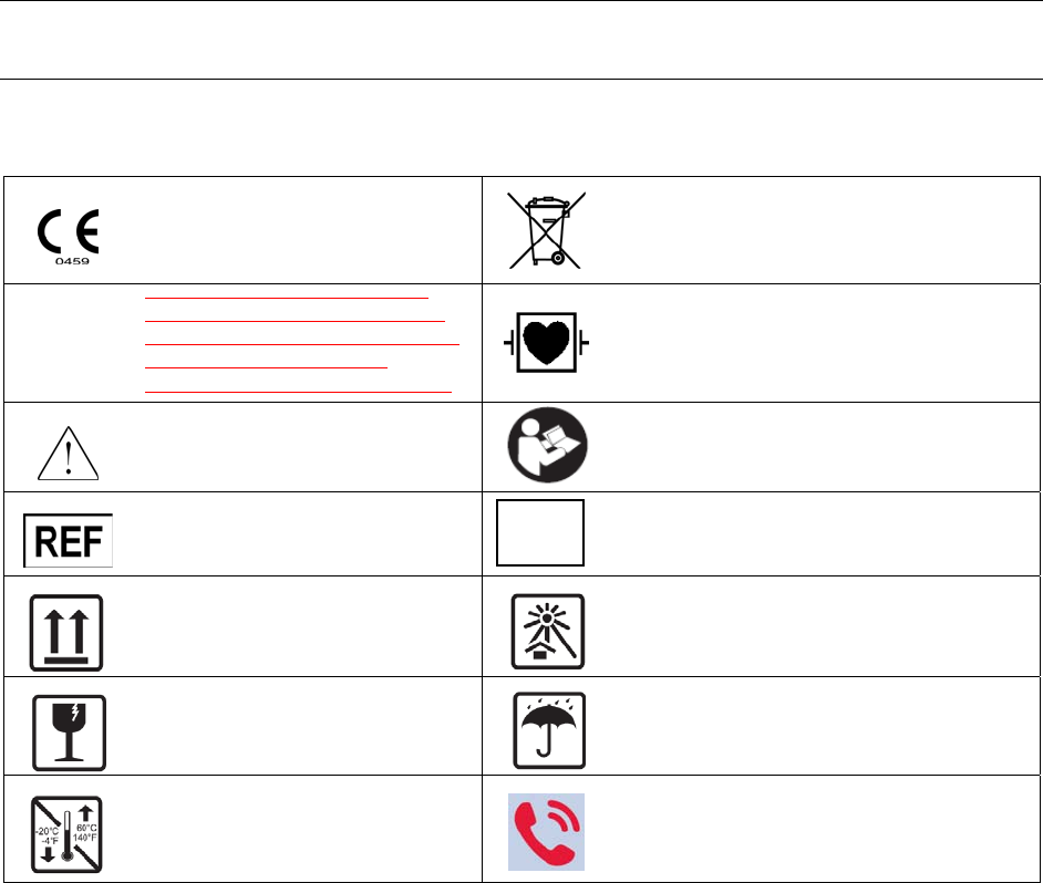
5. EQUIPMENT SYMBOLS AND MARKINGS
Symbol Delineation
Indicates compliance to applicable
European Union directives
Do not dispose as unsorted municipal waste. Per
European Union Directive 2002/96, requires
separate handling for waste disposal according to
national requirements
IPX4
Indicates device has been tested for
safety from vertically dripping water;
specifically, it indicates DRIP PROOF,
a higher than ordinary level of
protection from drips, leaks, and spills Defibrillator-proof type CF applied part
Caution Consult accompanying documents
Catalog number for relevant Mortara
part
Serial number
This end up Keep away from sunlight
Fragile, handle with care Keep dry
Storage temperature range
Nurse Call (waiting for final black and white
artwork)
SN

10
6. GENERAL CARE
Precautions
• Power off the telemetry transmitter before inspecting or cleaning.
• Protect the telemetry transmitter from liquids.
• Never immerse the telemetry transmitter in water.
• Do not drop the telemetry transmitter or subject to shock and/or vibration.
• Do not use organic solvents, ammonia-based solutions, or abrasive cleaning agents that may damage
equipment surfaces.
Inspection Prior to Clinical Use
Inspect your equipment prior to clinical operation. Do not use the equipment and contact an authorized service
representative for servicing if there are concerns about integrity of the system.
• Verify that all cables and connectors are securely seated.
• Check the case and chassis for any visible damage.
• Inspect keys and controls for proper function and appearance.
• Check for visually well balanced screen images.
• Inspect patient accessories for any visual damage.
• Patient input connector - Verify the pins on the patient input connector are all present and are not bent or
damaged in any way. The recessed area for the patient connector should be free from debris and clean. Use
compressed air to remove any debris that has entered into the connector area.
• Display – Verify there are no deep scratches or physical damage to the device display. Inspect the display
bezel to ensure it is firmly adhered to the device housing. Contact Mortara technical support if the display
or display bezel require replacement.
• Battery Door – Verify the battery door can be easily removed and that the spring contacts compress and
decompress with minimal force applied. Inspect the plastic door assembly for signs of excessive wear or
cracking, including the door seal to prevent fluid ingress. Replace the battery door assembly if necessary.
• Battery Compartment – Inspect the battery spring contacts and the battery door latching mechanism for
signs of excessive wear. If the battery compartment has been damaged, contact Mortara technical support
for assistance.
• Device Labeling – Inspect the device labeling for signs of wear and legibility. If the labeling is no longer
clear and legible, contact Mortara technical support for assistance.
Warning:
Servicing of this device should only be performed by Mortara authorized service personnel.
11
Preventive Maintenance Schedule:
Maintenance to be Performed Period Notes
Clean, disinfect and visually inspect unit 6 months Perform every 3 months if unit is in heavy use.
Equipment needed:
• Clean lint free cloth
• Mild detergent
• Luke warm water
Cleaning
The following section provides information on proper cleaning directions for the S4 telemetry transmitter and
patient accessories. Accessories should be cleaned before they are applied to a new patient. The telemetry
transmitter should be cleaned as per facility standard of care. Before cleaning, please refer to the cautions listed
below.
Warning:
• Remove the batteries from the device before inspecting or cleaning.
• Do not immerse the device in water or other fluids.
• Do not drop the device or subject it to shock and/or vibration.
• Do not use organic solvents, ammonia-based solutions, or abrasive cleaning agents which may damage
equipment surfaces.
Clean the exterior surface of the device with a damp, soft, lint-free cloth using a solution of mild detergent diluted in
water. After cleaning thoroughly dry off the device with a clean, soft cloth or paper towel.
Disinfecting
Warning:
• Be careful not to use an excessive amount of disinfecting solution that could lead to fluid entering the
device. Fluid ingress may cause irreparable damage to the internal circuitry.
• To disinfect the device, wipe the exterior surface with a damp, soft, lint-free cloth using a solution of 10%
Household bleach and water (Sodium Hypochlorite solution consisting of a minimum 1:500 dilution and
maximum of 1:10 dilution). Dry off the device with a clean, soft cloth or a paper towel.
CAUTION: Always disconnect the S4 telemetry transmitter from power source before cleaning.
12
CAUTION: Do not use harsh chemicals for cleaning. Do not use disinfectants that contain
phenol as they can spot plastics. Do not steam autoclave, gas sterilize, irradiate, subject to intense
vacuum, or immerse in water or cleaning solution. Be careful to avoid getting cleaning liquids into
connectors or the telemetry transmitter. If this occurs, allow the telemetry transmitter to dry in warm air
for 2 hours, then check to make sure all monitoring functions are working properly.
CAUTION: Keep the patient accessories off of the floor. Accessories that fall on the floor should
be inspected for defects, contamination, proper functionality, and cleaned or discarded according to the
approved recommendations.
CAUTION: The user has the responsibility to validate any deviations from the recommended
method of cleaning and disinfection.
Maintenance
The following table shows the recommended maintenance procedures for the S4 telemetry transmitter and its
accessories. The S4 telemetry transmitters should be serviced once a year by a Mortara authorized service
technician. However, it is good practice to periodically ensure the telemetry transmitter is in proper working order.
Perform these checks at least every 12 months by a qualified biomedical engineer or other trained service personnel.
To accomplish these steps in their entirety and verify the correct operation of the system, appropriate patient
simulators or other equipment may be required. Refer to the service manual for further details.
Functionality Procedure
Mechanical Integrity Check for cracks, abrasive edges and other signs of damage.
ECG / Respiration • Connect ECG leads to Patient Simulator.
• Verify proper heart rate at 30 and 300 bpm (+/- 2 bpm or +/- 1%).
• Verify 1 mV test pulse (Lead II).
• Verify proper respiration rate at 15 and 120 bpm (+/- 3 bpm).
Functionality Procedure
Touch screen Display Approved Cleaning Agents
• Clean the touch screen with a soft cloth moistened with either a solution of 70%
isopropyl alcohol in distilled water or soapy water.
Do not spray cleaner directly onto the touch screen. Spray the cleaner onto a lint-free cloth
and then wipe the monitor.
To clean the touch screen display,
1. Select the Settings sidebar button.
2. Select the Administrative menu.
3. Select the Screen Cleaning mode. This action disables the monitor’s touch screen for
15 seconds for cleaning purposes. After the 15 seconds expires, the touch screen
controls are reactivated.

13
ECG Cables
Approved Cleaning Agents
• Enzymatic detergent such as ENZOL (US) or CIDEZYME (outside the US)
• Distilled water
• Disinfectant solution (such as CIDEX OPA, or a 10% solution of household bleach
(5.25% sodium hypochlorite) in distilled water)
• Soft, lint-free cloths and/or soft-bristled brushes
• Protective gloves and eyewear
Procedure
1. Disconnect the telemetry transmitter from its power source.
2. Put on gloves and protective eyewear.
3. Prepare the enzymatic detergent according to the manufacturer's instructions, and also
the disinfectant solution, in separate containers.
4. Apply detergent to product using a soft, lint-free cloth. If material is dried on, allow
to sit for 1 minute. Do not immerse cable ends or lead wires in liquid as it can cause
corrosion.
5. Wipe smooth surfaces with the cloth.
6. Use a soft-bristle brush on visibly soiled areas and irregular surfaces.
7. Remove detergent from product using cloth dampened in distilled water.
8. Repeat as necessary.
9. Apply disinfectant solution on affected area using a soft cloth. Allow product to sit
for 5 minutes.
10. Wipe excess solution and clean product again with cloth dampened in distilled water.
11. Allow 2 hours for drying.
Battery Life and Charge Time
Battery Life
1. With a new, fully charged rechargeable battery pack installed, the device shall operate for a minimum of 32
hours.
2. When a fresh set of single-use alkaline (3) batteries are installed, the device shall operate for a minimum of
12 hours.
CAUTION: The battery should be removed from the telemetry transmitter completing each
clinical use. The battery may need to be replaced if it is no longer holding a charge.
WARNING: Use only APPROVED BATTERIES as listed in the Accessories section. Use of
unapproved batteries may cause a hazard and will void the warranty.
CAUTION: Batteries should only be replaced by a trained user.
Decommissioning and Disposal
Dispose of the telemetry transmitter, its components and accessories (e.g., batteries, cables, electrodes), and/or
packing materials in accordance with local regulations. Do NOT incinerate or throw the battery in garbage.

14
7. ELECTROMAGNETIC COMPATABILITY (EMC)
When using the telemetry transmitter, assess the electromagnetic environment affected by surrounding devices.
An electronic device may either generate or receive electromagnetic interference. Testing for electromagnetic
compatibility (EMC) has been performed on the telemetry transmitter according to the applicable international
standards.
The telemetry transmitter should not be used adjacent to or stacked with other equipment. If the telemetry
transmitter is used in this manner, verify the telemetry transmitter operates in an acceptable manner in the
configuration in which it will be used.
Fixed, portable, and mobile radio frequency communications equipment may affect the performance of medical
equipment. See Table X-4 for recommended separation distances between the radio equipment and the telemetry
transmitter.
The use of accessories, transducers, and cables other than those specified by Mortara Instrument may result in
increased emissions or decreased immunity of the equipment.

15
Table X-1 Guidance and Manufacturer’s Declaration: Electromagnetic Emissions
The equipment is intended for use in the electromagnetic environment specified in the table below. The customer or
the user of the equipment should ensure that it is used in such an environment.
Emissions Test Compliance Electromagnetic Environment: Guidance
RF Emissions
CISPR 11 Group 1 The S4 telemetry transmitter uses RF energy only for its internal
function. Therefore, its RF emissions are very low and not likely to
cause any interference in nearby electronic equipment.
RF Emissions
CISPR 11 Class A The S4 telemetry transmitter is suitable for use in all establishments
other than domestic and those directly connected to the public low-
voltage power supply network that supplies buildings used for
domestic purposes.
Harmonic Emissions
IEC 61000-3-2 Not Applicable
Voltage Fluctuations/
Flicker Emissions
IEC 61000-3-3
Not Applicable
Table X-2 Guidance and Manufacturer’s Declaration: Electromagnetic Immunity
The equipment is intended for use in the electromagnetic environment specified in the table below. The customer or
the user of the equipment should ensure that it is used in such an environment.
Immunity Test IEC 60601 Test Level Compliance Level Electromagnetic Environment: Guidance
Electrostatic
discharge (ESD)
EN 61000-4-2
+/- 6 kV contact
+/- 8 kV air +/- 6 kV contact
+/- 8 kV air Floors should be wood, concrete, or ceramic
tile. If floors are covered with synthetic
material, the relative humidity should be at
least 30%.
Electrical fast
transient/burst
EN 61000-4-4
+/- 2 kV for
power supply lines
+/- 1 kV for
input/output lines
+/- 2 kV for
power supply lines
+/- 1 kV for
input/output lines
Mains power quality should be that of a
typical commercial or hospital environment.
Surge
IEC 61000-4-5 +/- 1 kV differential mode
+/- 2 kV common mode +/- 1 kV differential
mode
+/- 2 kV common mode
Mains power quality should be that of a
typical commercial or hospital environment.
Voltage
fluctuations and
Interruptions
<5% UT for 0.5 cycles
40% UT for 5 cycles
70% UT for 25 cycles
<5% UT for 5s
<5% UT for 0.5 cycles
40% UT for 5 cycles
70% UT for 25 cycles
<5% UT for 5s
Note that monitoring is interrupted at the
level “< 5% UT for 5s”, but equipment
remains safe (as specified in
EN 60601-1-2).
Power frequency
(50/60 Hz)
magnetic field
IEC 61000-4-8
3 A/m 3 A/m Power frequency magnetic fields should be
at levels characteristic of a typical location
in a typical commercial or hospital
environment.
NOTE: UT is the AC Mains voltage prior to application of the test level.
16
Table X-3 Guidance and Manufacturer’s Declaration: Electromagnetic Immunity
The equipment is intended for use in the electromagnetic environment specified in the table below. The customer or
the user of the equipment should ensure that it is used in such an environment.
Immunity Test IEC 60601 Test
Level Compliance
Level Electromagnetic Environment: Guidance
Conducted RF
EN 61000-4-6
3 Vrms
150 kHz to
80 MHz
3 Vrms
150 kHz to
80 MHz
Portable and mobile RF communications equipment should
be used no closer to any part of the equipment, including
cables, than the recommended separation distance calculated
from the equation applicable to the frequency of the
transmitter.
Recommended separation distance
d = 1.2
d = 1.2 80 MHz to 800 MHz
d = 2.3 800 MHz to 2.5 GHz
Where P is the maximum output power rating of the
transmitter in watts (W) according to the transmitter
manufacturer and d is the recommended separation distance
in meters (m).
Field strengths from fixed RF transmitters, as determined by
an electromagnetic site surveya, should be less than the
compliance level in each frequency rangeb.
Interference may occur in the vicinity of equipment marked
with the following symbol:
Radiated RF
IEC 61000-4-3
3 V/m
80 MHz to
2.5 GHz
3 V/m
80 MHz to
2.5 GHz
a. Field strengths from fixed transmitters, such as base stations for radio (cellular/cordless) telephones and land
mobile radios, amateur radios, AM and FM radio broadcast, and TV broadcast cannot be predicted theoretically
with accuracy. To assess the electromagnetic environment due to fixed RF transmitters, an electromagnetic site
survey should be considered. If the measured field strength in the location in which the equipment is used
exceeds the applicable RF compliance level above, the equipment should be observed to verify normal
operation. If abnormal performance is observed, additional measures may be necessary, such as reorienting or
relocating the equipment.
b. Over the frequency range 150 kHz to 80 MHz, field strengths should be less than [3] V/m.

17
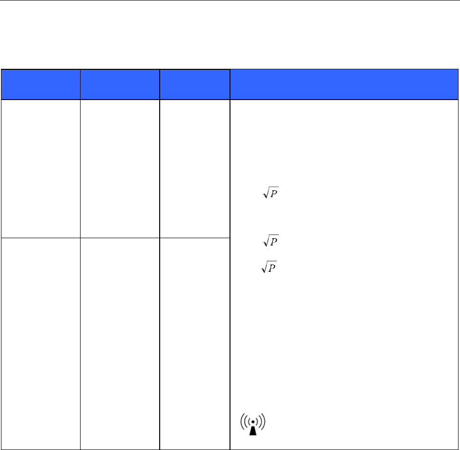
Table X-4 Recommended Separation Distances Between Portable and Mobile RF Communications
Equipment and the Equipment
The equipment is intended for use in the electromagnetic environment in which radiated RF disturbances are
controlled. The customer or the user of the equipment can help to prevent electromagnetic interference by
maintaining a minimum distance between portable and mobile RF communications equipment (transmitters) and the
equipment as recommended in the table below, according to the maximum output power of the communications
equipment.
Rated Maximum Output
Power of Transmitter (W) Separation Distance According to Frequency of Transmitter (m)
150 KHz to 80 MHz 80 MHz to 800 MHz 800 MHz to 2.5 GHz
d = 1.2 d = 1.2 d = 2.3
0.01 0.12 m 0.12 m 0.23 m
0.1 0.38 m 0.38 m 0.73 m
1 1.2 m 1.2 m 2.3 m
10 3.8 m 3.8 m 7.3 m
100 12.0 m 12.0 m 23.0 m
For transmitters rated at a maximum output power not listed above, the recommended separation distance d in
meters (m) can be estimated using the equation applicable to the frequency of the transmitter, where P is the
maximum output power rating of the transmitter in watts (W) according to the transmitter manufacturer.
NOTE: At 80 MHz and 800 MHz, the separation distance for the higher frequency range applies.
NOTE: These guidelines may not apply in all situations. Electromagnetic propagation is affected by
absorption and reflection from structures, objects, and people.

18
USA and Canada Radio Regulations
USA (FCC)
This device is equipped with Transmitter Module with FCC ID:RYYWYSAAVDX7
This device complies with part 15 of the FCC Rules. Operation is subject to the following two conditions:
(1) This device may not cause harmful interference, and
(2) this device must accept any interference received, including interference that may cause undesired operation.
[Caution] Changes or modifications not expressly approved by the party responsible for compliance could void the
user’s authority to operate the equipment.
This device with transmitter module has been tested to SAR and complies to FCC exposure requirements for
portable devices. SAR testing has been done at a distance of 10mm from the face and 0mm from the body.
Canada (IC)
This device is equipped with Transmitter Module with IC:4389B-WYSAAVDX7.
This device complies with Industry Canada license-exempt RSS standard(s).
Operation is subject to the following two conditions:
(1) this device may not cause interference, and
(2) this device must accept any interference, including interference that may cause undesired operation
of the device."
This device with transmitter module has been tested to SAR and complies to IC exposure requirements for portable
devices. SAR testing has been done at a distance of 10mm from the face and 0mm from the body.
(French)
Cet appareil est équipé d'un module émetteur avec marque IC:4389B-WYSAAVDX7
L’appareil conforme aux CNR d'Industrie Canada applicables aux appareils radio exempts de licence.
L'exploitation est autorisée aux deux conditions suivantes:
(1) l'appareil ne doit pas produire de brouillage, et
(2) l'appareil doit accepter tout brouillage radioélectrique subi, même si le brouillage est susceptible d'en
compromettre le fonctionnement.
Cet appareil avec module émetteur a été testé pour les taux d'absorption spécifique (DAS) et est conforme aux
normes d'exposition d'IC pour les appareils portables. Tests de DAS ont été réalisés à une distance de 10mm du
visage et du corps 0mm.
This device is defibrillator protected in compliance with AAMI standards and IEC 60601-2-25.

19
8. INTRODUCTION
General Information
This User's Guide provides information for users of the Mortara S4 telemetry transmitter. It is written for clinical
professionals who are expected to have a working knowledge of medical procedures and terminology as required
for monitoring cardiac patients.
The S4 telemetry transmitter is a small, lightweight telemetry transmitters designed to acquire an ECG and to
transmit this data to the Surveyor Central Monitoring station.
The S4 digital ambulatory transmitter user manual explains how to:
• Acquire and transmit ECG and Impedance respiration signals to the Surveyor Central Station
• Setup device configurations
NOTE: This manual may contain renderings of various display screens. Any screen images are provided for
reference only and are not intended to convey actual operating techniques.
Indications For Use
• The S4 telemetry transmitter is indicated for use in adult & pediatric patient populations. The Mortara S4
telemetry transmitter facilitate the monitoring of ECG monitoring and Impedance respiration.
• The S4 telemetry transmitter is a prescription device intended to be used by knowledgeable healthcare
professionals within a healthcare facility.
• The S4 telemetry transmitter is indicated for use in a clinical setting by a physician, or by trained personnel
who are acting on the orders of a licensed physician. It is not intended as a sole means of diagnosis.
• The S4 telemetry transmitter is indicated for use to acquire and output electrocardiographic data.
• Indicated for use as a radiofrequency physiological signal transmitter, receiving and delivering real-time
acquisition and RF transmission of simultaneous 12-lead ECG data, while allowing the patient to be
ambulatory within the range of the antenna network.
Contraindications
• The S4 telemetry transmitter is not intended to be used as a vital signs physiological monitor.
• The S4 may not render and ECG while an ESU is being actively used on the connected patient.
20
System Description
The S4 telemetry transmitter represents wireless electrocardiographic technology. It provides a means to acquire and
transmit simultaneous 12-lead ECG data, with diagnostic quality to a Surveyor Central Station monitoring system while
allowing the patient to be ambulatory within the range of the antenna network.
The S4 uses a three (3) AA alkaline batteries or (1) rechargeable battery pack. The rechargeable battery may only be
charged by the Surveyor Battery Charger.
The following equipment is necessary to use the S4 telemetry transmitter:
• One (1) Rechargeable Li-Ion Battery Pack or three (3) AA batteries
• Surveyor Central Station Monitoring System
• Applicable Patient Cable, lead wires and electrodes
• Antenna network
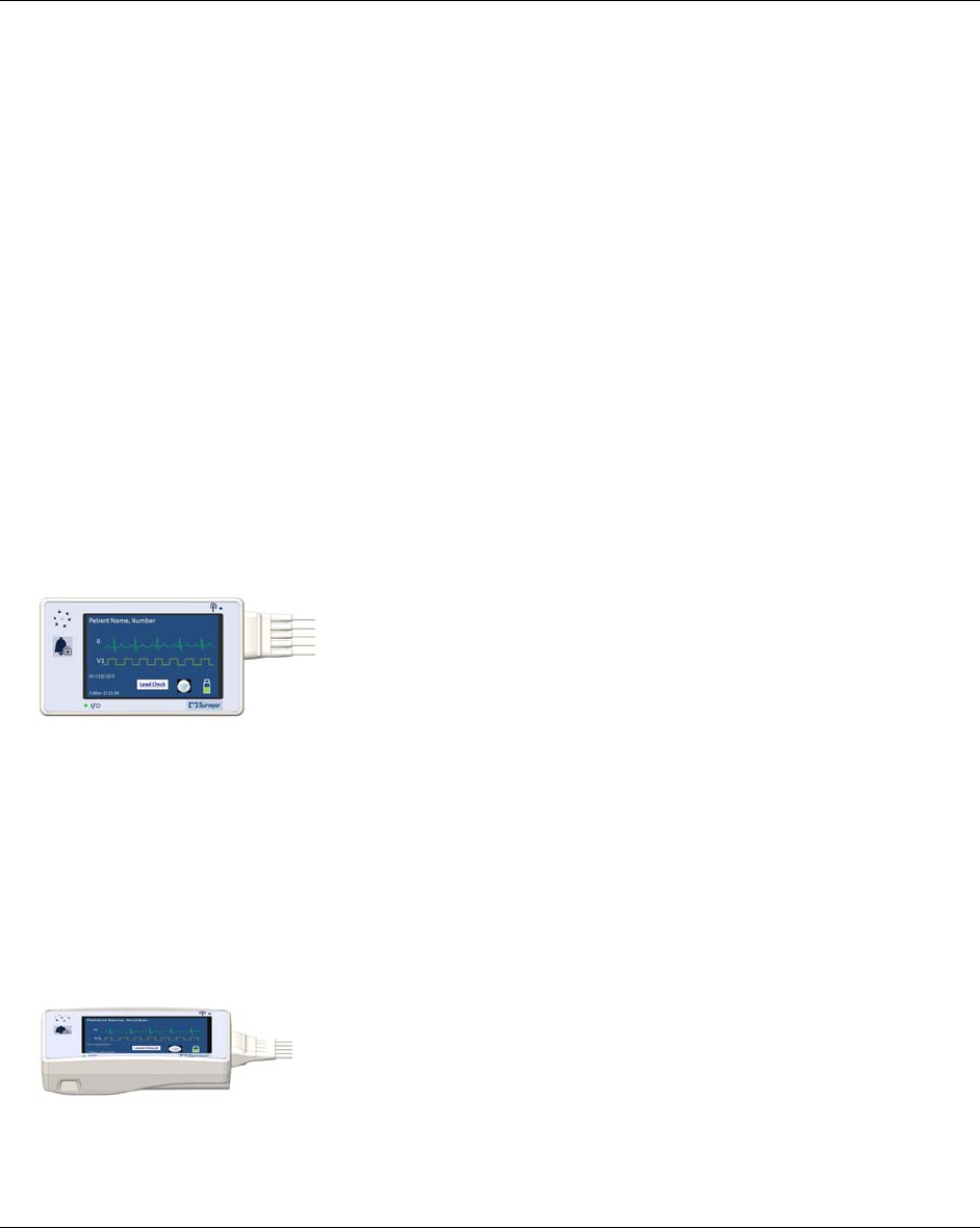
Front View
S4 Telemetry transmitter: Front View Example
1. Speaker
2. Main Screen Display Area
3. Control Button
Side View showing battery door
21
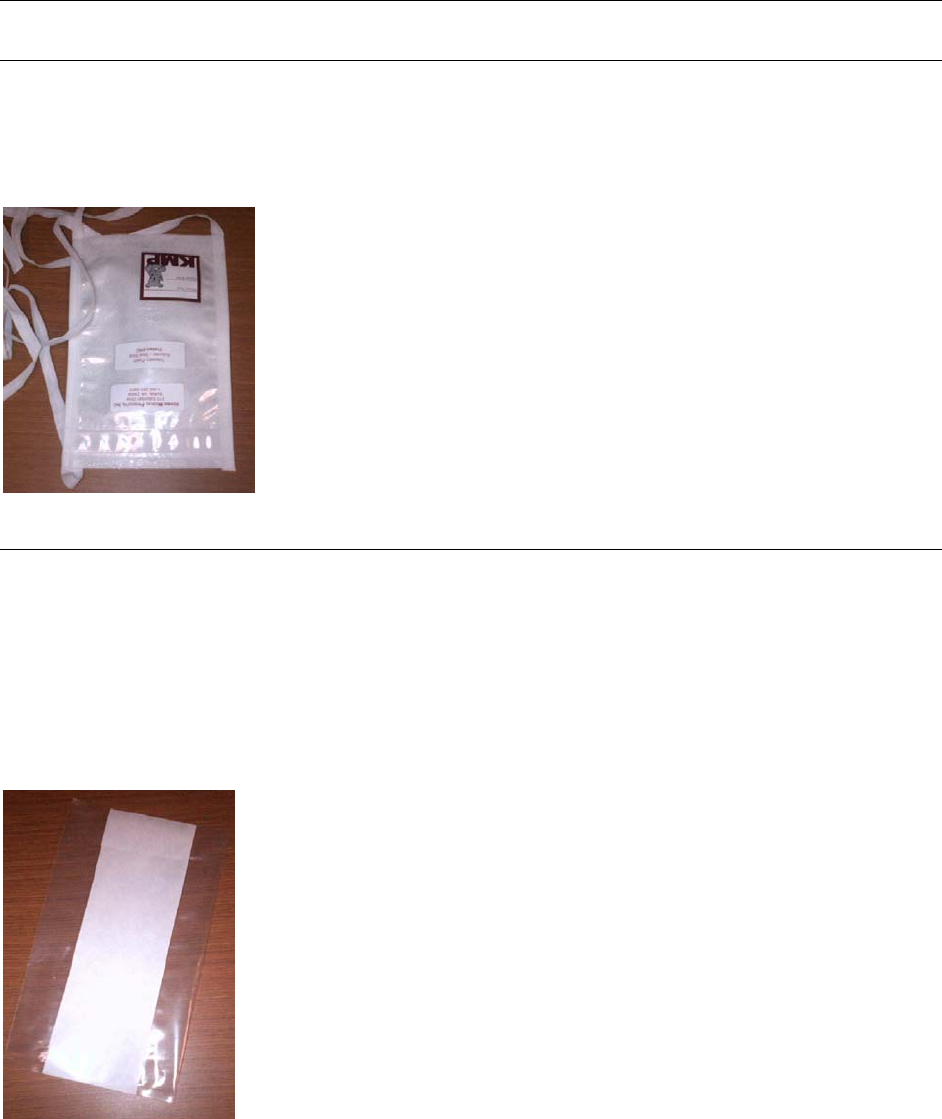
Carrying Pouch
The S4 may be worn by the patient in the disposable pouch that is tied to the patient. The pouch is designed to fit
the contours of the telemetry pack.
The transparent film allows viewing of the screen and operation of the nurse call button.
Tie-on Pouch
The S4 may be worn by the patient in the disposable pouch that is adhered to the patient’s clothing. This single
patient use device is fully biocompatible, with adhesive designed for attachment to a variety of surfaces and
clothing.
The pouch is designed to fit the contours of the telemetry pack. The transparent film allows viewing of the screen
and operation of the nurse call button.
Stick-On Pouch

22
9. UNPACKING AND SET UP
Checking Contents
Depending on the exact configuration ordered, your system may include the following components:
• S4 Transmitter complete with configured Surveyor ECG Acquisition Module (SAM) and a detachable
battery door.
• ECG cables available with the SAM module
o 12 lead cable
• ECG electrodes available use with the S4 Transmitter
o Box of 10 electrodes
o Case of 100 electrodes
• Power Pack and Charging Options
o One (1) Li-Ion Rechargeable Battery Pack
o Three (3) Alkaline AA batteries (not included)
o Five Bay Multiple Battery Charger Kit, with Li-Ion Rechargeable Battery Pack
• Pouch Options
o Disposable Tie-On Pouch (Qty 5 included)
o Disposable Stick-On Pouch (Qty 5 included)
• Alkaline Battery Convenience Tray
o Reusable Battery Tray. Qty 1 included. This plastic mount conveniently loads three alkaline AA
batteries into the battery compartment. Battery Tray not essential for alkaline battery installation.
Battery Installation
The battery compartment is accessible via the removable battery door.
1. Remove the Battery Door by pinching the grips located on each side of the door and remove.
2. Load the battery into the battery compartment:
a. Insert the rechargeable Li-Ion battery into the battery compartment. Align the battery above the contacts in
the compartment. Then slide the battery down to lock it mechanically in place as it makes electrical
contact. This pack fits in one way. A new Li-Ion Battery will last approximately 32 hours on a full charge.
Only recharge using Mortara model CML5 Multiple battery charger.
OR…

23
b. Insert three (3) AA alkaline batteries into the battery compartment using the convenience tray. Align the
tray for easy insertion. The batteries can also be loaded without the tray by aligning them with the positive
(+) and negative (-) indicators on the battery matching the same designators in the battery compartment.
4. Replace the battery door. Position the hinged corners first, then rock the lid down until it battery door locks
snap the grips into place.
10. OPERATION
Turning the S4 On
• The S4 will power up after either the rechargeable battery pack, or the last alkaline battery, is inserted into the
battery compartment.
Setting the Passcode
• When powered ON, the S4 will display the SETTINGS screen.
o Press the Reset Passcode touch-key.
o Enter a three digit Passcode using the keypad, and SAVE.
o Exit the SETTINGS screen.
Turning the S4 Off
• Power OFF the S4 by removing the internal battery.
• Use the Shut Down touch-key located in the Utility Screen.

24
Resume Operation After Shutdown
• Pressing the Nurse Call button to enter the Resume Operation screen.
• Pressing the [CANCEL] touch-key will cancel the Nurse Call signal destined for the central station, and instead
enter the HOOK-UP screen.
• Not pressing the [CANCEL] touch-key within 20 seconds will transmit the Nurse Call signal to the central
station and the display will dim to black.
Entering a Passcode
• Power the S4 ON by loading the battery or by resuming operation (see above). The LED indicators will flash.
• Within a few seconds the HOOK-UP screen will appear.
• Pressing the TOOLBOX touch-key will enter the Unlock Screen. This screen is displayed whenever the
operator tries to perform a protected action such as entering in the Utility screen before unlocking S4 with the
correct Passcode.
• Enter the correct (preset) passcode using the keypad. Then press OK or one of the following touch-keys:
o OK (will verify the entered code against the preset valid passcode)
o CL (will clear the entered code)
o CANCEL (will cancel the requested action)
Connecting S4 to the Surveyor Central Station
• Connection of the S4 transmitter to the Surveyor Central Station is automatic on power ON of the S4. The LED
located below the WIFI icon indicates that the S4 is connected to the central station when the LED is
illuminated, and flashes when the S4 is searching for WiFi connection.
NOTE: Refer to the service manual for further details on central station networking.
25
Icon Touch-keys and Screens
The S4 contains a touch screen user interface for operator interaction. The operator can recognize when
definitively pressing the on-screen touch-keys, screens and Nurse Call button, by an audible sound from the S4
speaker. A list of touch-keys, buttons, icons and indicators and their functionality follows.
• PATIENT HOOK-UP
Press this touch-key icon to enter the hookup screen.
The HOOK-UP screen allows the operator to visualize the ensure quality electrode connection and proper
location placement. Note the effectiveness of the patient electrode and lead wire interface connection by the
color of the dot indicators on the screen torso.
The Hook-Up Screen
Pressing the Torso image will display the Patient Information Screen (if a patient record is associated to the
configured monitoring slot on the central station). The HOOK-UP screen displays patient demographics
information if available from the central station. The operator may configure the page header to display either
the patient ID or the Patient Name.
The accessible touch-keys available from the HOOK-UP screen are:
o ECG (displays streaming ECG waves)
o TOOLBOX (tools for adjusting ECG waveform, other utilities)
o START (starts an active session)
NOTE: The START touch-key begins the monitoring session if the S4 finds connection to the central
station, otherwise the START touch-key will be grey (disabled).
26
• ECG WAVEFORM
Press this touch-key icon to enter the ECG Waveforms Screen.
ECG touch-key icon
Pressing the ECG touch-key displays the patient’s real time streaming ECG waveforms and information.
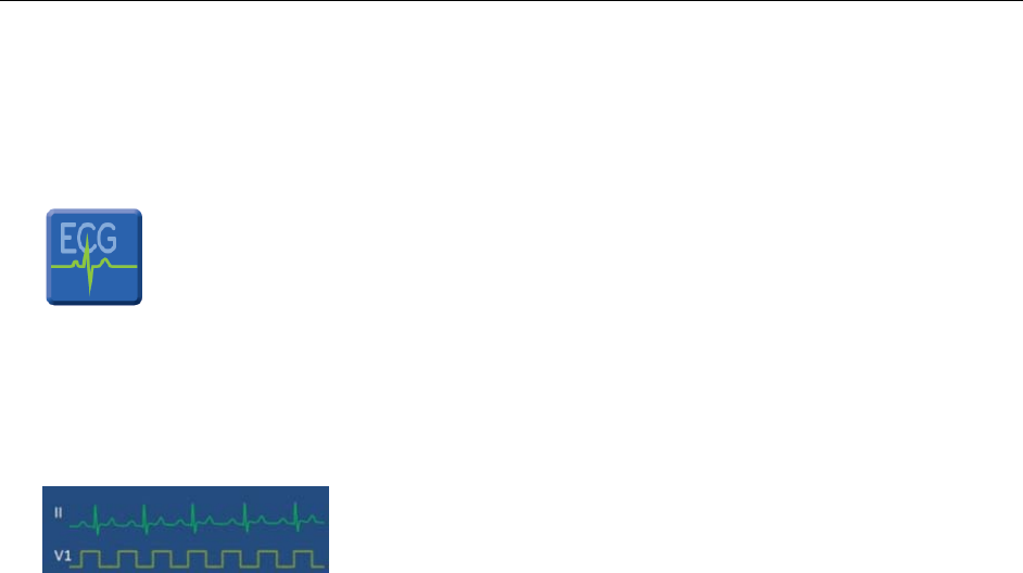
• ECG WAVEFORM SCREEN
The ECG Waveforms Screen
Touching the ECG WAVEFORM screen toggles through the displayed lead set choices:
o LA-RA, LL-RA/LL-LA, V1-RA/LA,.., V6-RA/LA (8 leads);
o LA-RA, LL-RA/LL-LA, V1-RA/LA, V2-RA/LA
o V3-RA/LA, V4-RA/LA, V5-RA/LA, V6-RA/LA
NOTE: Precordial lead labels will depend on the current reference lead.
The touch-keys available to the operator in the ECG WAVEFORM screen include:
o HOOK-UP (visualize quality electrode connection)
o PRINT (Print to the central station printer; disabled if not actively monitoring)
o START (begin a monitoring session; disabled if not connected to central station)
o NUMBERS (display parameters if a monitoring session is currently in progress)
27
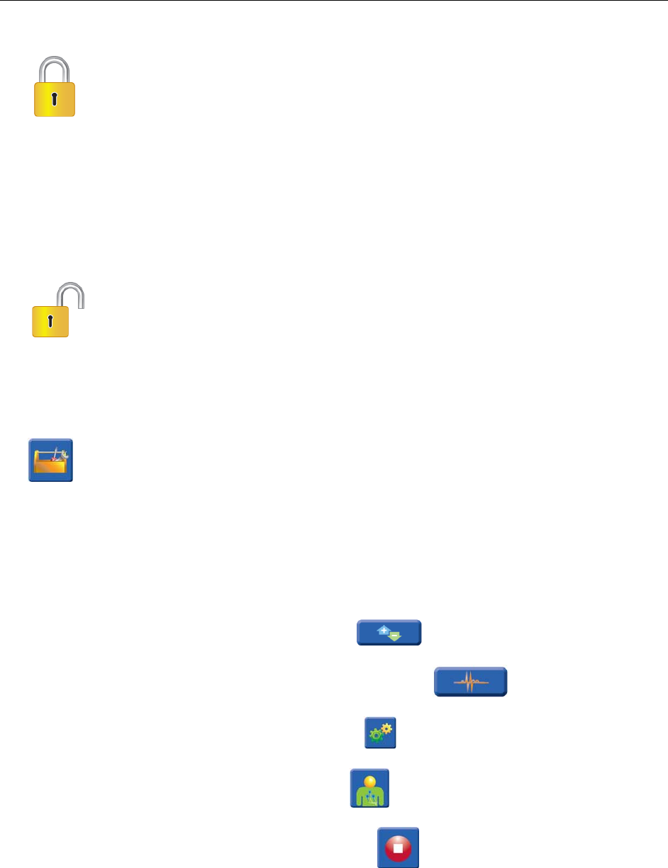
• UNLOCK THE S4 WITH PASSCODE
This icon appears when the S4 is LOCKED.
The S4 is locked so the patient can’t enter the operator screen. The operator needs to UNLOCK the S4 prior to
making any changes to the S4. To unlock the S4:
o Press the TOOLBOX touch-key (with the S4 locked) to open the UNLOCK Screen.
o Enter the valid Passcode into the numeric touchpad and press OK.
This icon appears after the S4 is UNLOCKED with the valid Passcode.
• TOOLBOX
Pressing the TOOLBOX icon (with the S4 unlocked) enters the Utility Screen.
The Utility Screen provides access to various functions. This screen is displayed whenever the operator tries to
perform a protected user function. Once the correct Passcode is entered, functions can be completed by the
operator from the UTILITY screen.
The UTILITY Screen provides submenus for navigation and to select the desired ECG waveform setting.
o GAIN (allows adjustment of the ECG gain)
o SPEED (allows adjustment of the ECG waveform speed)
o SETTINGS (allows Configuration of the S4)
o HOOK-UP (returns to the Hookup screen)
o SHUTDOWN (powers OFF the S4 transmitter)

28
• SAME PATIENT
SAME PATIENT
Pressing the SAME PATIENT touch-key identifies the demographics for the previous patient and returns to the
HOOK-UP screen, for confirmation of quality electrode connection and proper lead placement.
• NEW PATIENT
NEW PATIENT
Pressing the NEW PATIENT touch-key starts a blind session, and returns to the HOOK-UP screen, for
confirmation of quality electrode connection and proper lead placement.
• START
START touch-key icon
Pressing this touch-key begins the newly prepared patient’s session.
• NUMBERS
NUMBERS touch-key icon
Pressing the NUMBERS key during an active session displays the Heart Rate value returned by the central
station.
29
• PRINT
PRINT touch-key icon
Pressing the PRINT touch-key sends a print request to the central station during an active session. This key is
disabled if the monitoring session is suspended.
• BATERY INDICATOR
BATTERY indicator
This icon changes to indicate the current approximate energy charge remaining on the S4 battery.
• RESPIRATION
RESPIRATION icon touch-key
Pressing the RESPIRATION touch-key displays the respiration reported to the central station.
• SETTINGS Screen (authorized personnel only)
SETTINGS icon touch-key
The SETTINGS screen provides a means to:
o Configure S4’s transmission functionality for use with the central station (qualified IT specialist)
o Set the user language (authorized key operator)
o Reset the password (authorized key operator)
o Reset screen calibration (authorized key operator)
o Display version information (authorized key operator)

30
SETTINGS should be addressed by technically qualified and authorized personnel. Reconfiguration cannot be
updated while in monitoring session. The various subpages are accessible from the SETTINGS screen:
o HOST (qualified IT specialist configures Central Station connectivity settings)
o NETWORK (qualified IT specialist enters the network and WLAN settings)
o LANGUAGE (key operator selects the user interface language)
o WW-FI DIAGNOSTICS (qualified IT specialist access to current wi-fi settings and information)
o RESET PASSCODE (key operator enters new Passcode)
o RESET CALIBRATION (key operator chooses power up in Screen Calibration mode)
o VERSION (displays the hardware and software versions for the transmitter)
o SAM VERSION (displays the hardware and software versions for the SAM)
Nurse Call Button, Speaker, and LED Indicators
• NURSE CALL for the patient
NURSE CALL push-button
During an active session this button acts as a conventional NURSE CALL button, sending a signal to the
attendant at the central station. When a session is not in progress, the NURSE CALL button turns OFF the
Surveyor S4.
• POWER ON/OFF LED
Power ON/OFF Indicator Label
The LED below this icon indicates that the S4 is powered ON when the LED is illuminated, powered OFF
when the LED is not illuminated, and flashes while waiting for passcode entry.

31
• WIFI LED
WIFI Bezel Icon
The LED located below this icon indicates that the S4 is connected to the central station when the LED is
illuminated, and flashes when not connected and searching for WiFi connection.
• SPEAKER ICON
Speaker Icon
The S4 speaker located beneath this icon provides the audible sound associated with the recognition of a screen
touch-key or the Nurse Call button.

32
Patient Information, Status and Messages
The S4 displays information and status messages in the top area of the display. These messages provide timely
S4 information to the operator. Changing color message banners provide for easy recognition by the operator.
The operator may choose to display either the Patient ID or the Patient Name (“Last, First”) on the display
header. This selection is made when the Hookup Screen is active and the operator selects the patient or
indicates the start of a BLIND session, with no patient demographics associated with a central station slot.
o A conflict notification message will appear if the central station monitoring slot allocated to this S4, is
currently monitored by another S4.
o If a conflict between two S4s should occur the operator would either:
a) Update his particular S4 device configuration
b) Shutdown his S4
c) Shut down the other S4.
o To change the configuration, a key operator press the SETTINGS touch-key to access the
Configuration screen.
Several icons indicate the status of the S4 systems, transmission and session, as follows:
o PADLOCK (locked or unlocked, indicates if the correct passcode has been entered)
o WIFI (indicates the transmitter’s radio signal transmission quality)
o BATTERY (indicates the current battery charge)
o TIME (format in Hours: Minutes: Seconds)
o SLOT NAME (monitoring slot name reported to the Central Station, if connected)
o STATUS (current session status: DISCHARGED, SUSPENDED, MONITORING)
Patient Information is displayed when the transmitter is connected to the central station. The color banner will
appear in RED when the S4 is not connected to the central station, with a message “Trying to connect to
Central”. The S4 will continuously try to connect to the central station as it continues to display the current
time.
33
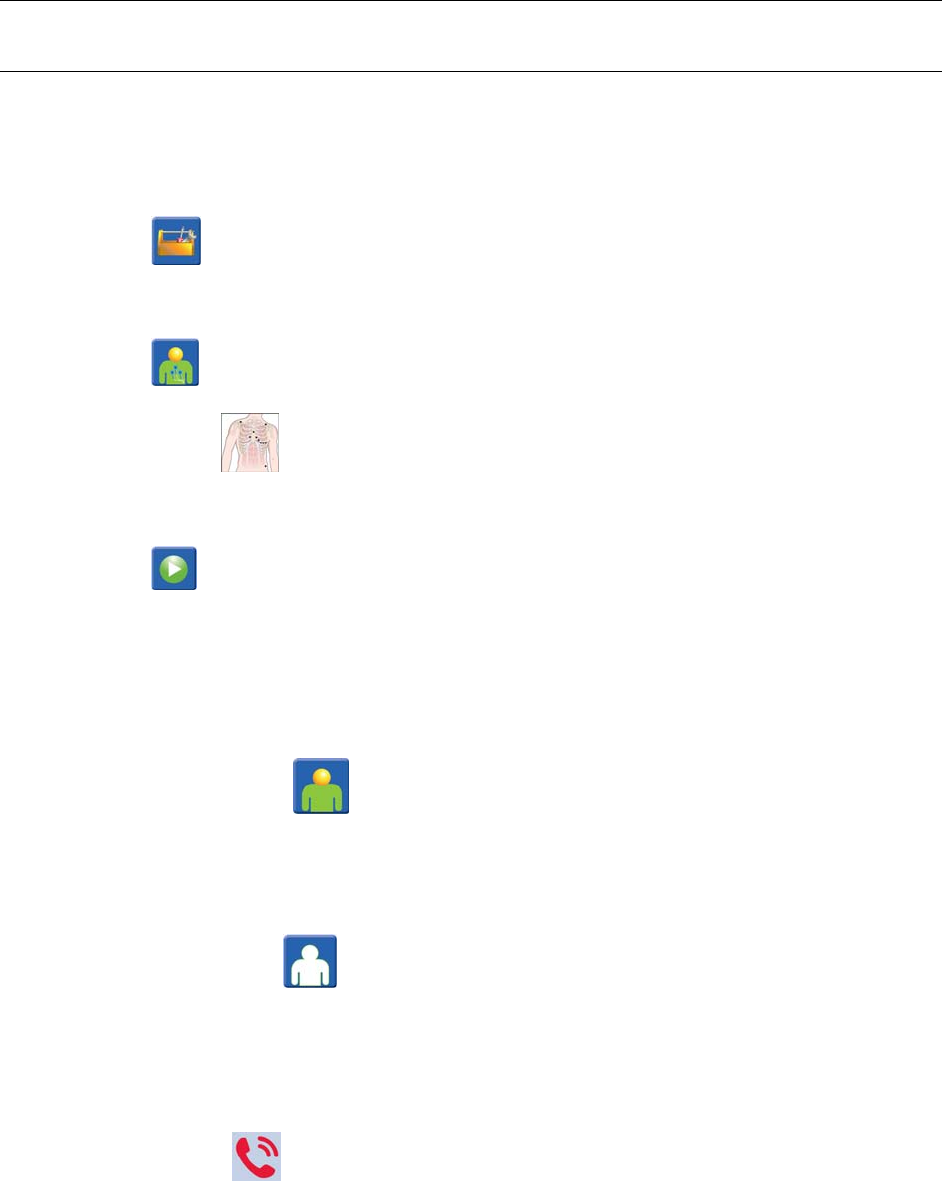
10. STARTING A MONITORING SESSION
Starting a Monitoring Session
1. Insert the battery into the S4 to turn ON the device.
2. Press the touch-key to enter the UNLOCK Screen.
3. Enter the Passcode to unlock the S4 device.
4. Press the touch-key. Attach the electrodes and lead wires to the patient.
NOTE: Using the screen’s Torso image, visualize the proper electrode placement locations and
attach electrodes and lead wires to the patient to achieve all green indications, to assure a high quality
signal.
5. Press the touch-key to enter the Start Session screen.
NOTE: The Start Session screen allows the operator to start a monitoring session. The top of the screen
will display the Information Header. A dropdown menu will be populated with the list of profiles currently
available on the central station.
6. Select the patient
o Press the SAME touch-key to restart the previous monitoring session preserving the
patient record last associated with the monitoring slot. The touch-key is grey (disabled) if there is
no patient record associated with that central station slot.
Or…
o Press the NEW touch-key to start a new monitoring session where no patient
demographics yet entered (blind session). The session will use the profile currently selected in
the dropdown menu.
7. To end a session, first activate the S4 operation capability:
a) Press the button to activate the screen.
b) Press the [ABORT] touch-key within 20 seconds, to cancel the Nurse Call signal and resume
operation of the S4 device.

34
8. Press the touch-key to access the Utility Screen.
9. Press the touch-key and confirm (OK) shutdown.
NOTE: The SHUTDOWN command will turn OFF the S4 device and suspend the active monitoring
session. Choose Cancel to re-open the HOOK-UP screen, or OK to power down and suspension (end) the
monitoring session.
NOTE: Shutting down the S4 during an active session with an identified patient will end (suspend) the
session and will save the monitored data.
CAUTION: Shutting down the S4 during an active blind session will end the session and will not save the
monitored data.

35
11. PATIENT PREPARATION FOR QUALITY ECG
Overview
Quality ECG Data Acquisition
The ECG electrodes sense the electrical signals generated by the electrical activity of the heart as it beats. The S4
transmitter amplifies the signals so they can be displayed on the screen.
The S4 transmitter is configured to a specific Surveyor Acquisition Module (SAM) and appropriate ECG cable. The
12-Lead SAM uses the LeadForm 12 lead ECG cable.
Obtaining quality ECG data is important in continuous ECG monitoring. A quality ECG signal depends largely on
the patient prep and electrode placement. Direct contact between the electrodes and the patient's skin and correct
placement of the electrode can help ensure obtaining quality ECG data.
A good quality ECG contains:
• Discernible P waves, QRS complexes, and T waves.
• Good R wave detection.
• Steady, even, crisp baseline.
• Absent of respiratory variability, artifact, noise, and other interference.
A good quality ECG may enhance the performance of the arrhythmia algorithm and may lessen false erroneous
alarm notifications.
A poor quality ECG may be caused by many factors:
• Poor site preparation may lead to poor quality ECG data.
• Poor electrode application may lead to poor quality ECG data.
• Patient movement may lead to poor quality ECG data.
• Interference by other equipment in the room may lead to poor quality ECG data.
• Poor quality ECG becomes synonymous with artifact and interference in the ECG waveforms.
A poor quality ECG may manifest in several ways:
• Superfluous baseline artifact.
• Erratic baseline.
• Sharp “spikes.”
• Rolling, wandering waveforms as seen with patient breathing patterns.
• Difficult to discern P waves from atrial fib waves from noise.
• Poor R wave detection.
• Inability to discern P waves, QRS complexes, T waves.
Artifact and interference in the ECG waveforms may be caused by using accessories, lead wires, and ECG cables
other than those specified to work with the S4 telemetry transmitters. Always use accessories, lead wires, ECG
cables, and other accessories specified to work with the S4 telemetry transmitters.

36
Skin Preparation
In continuous ECG monitoring, the goal of skin preparation is to maximize the surface area of direct contact
between the patient’s skin and the ECG electrode. Follow the facility’s standard of care when preparing the
patient’s skin for ECG electrode placement and ECG monitoring.
To prepare the patient’s skin for electrode placement:
1. Explain the procedure to the patient.
2. Maintain patient privacy during skin prep and electrode placement.
3. Locate the correct anatomical landmarks for electrode placement.
4. Clip or shave excess hair in the areas marked for electrode placement.
5. Remove residual skin oils, creams, and lotions by gently abrading the skin with a small gauze pad.
NOTE: With elderly or frail patients take care to not abrade the skin causing discomfort or bruising.
Clinical discretion should always be used in patient preparation.
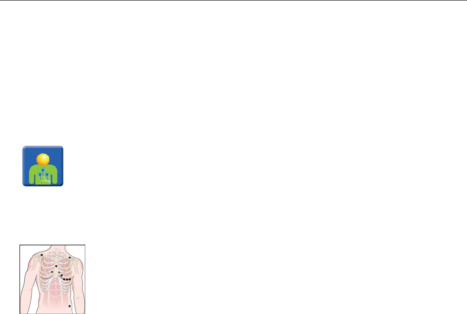
Electrode Placement
To apply electrodes:
1. Use pre-gelled, Ag/AgCl disposable electrodes.
a. Do not use electrodes after their expiration date, or if the gel has dried out.
Store electrodes in an air tight container.
Electrodes dry out if not stored properly leading to loss of adhesion and conductivity.
b. Always use the same electrodes.
Do not mix electrode brands or types.
Using different types of electrodes may cause a fluctuation in the impedance and this can lead to
baseline artifact and noise in the ECG tracing.
2. Apply the electrodes in the following manner:
a. Attach the electrode to the ECG lead wires prior to attaching the electrode to the patient’s chest.
b. Place the electrode in the properly prepared, correct location by using a circular motion on the
electrode adhesive area.
c. Gently press the electrode adhesive to the patient’s skin until the entire outer surface of the electrode is
adhered to the patient’s chest.
d. Once the electrode adhesive is attached, gently press on the gel area to ensure proper gel to chest
contact. Avoid dislodging the gel as the displaced gel can increase baseline artifact and noise in the
ECG tracing.
e. Test for firm electrode contact by slightly tugging on the electrode to check for adhesion among the
entire electrode surface. If the electrode moves freely, change the electrode. If the electrode does not
move easily, a good adhesive contact has been obtained.
Refer to the Electrode Location section in this manual for further details on correct anatomical landmarks for
electrode placement.
Best Practice Recommendation: Change electrodes as per hospital standard of care, or at least every 24 hours to
enhance patient skin care and the acquisition of quality ECG data. Clinical discretion should always be used in
patient preparation.

37
13. PATIENT ELECTRODE HOOK UP
Pacemaker Patients
Pacemaker patients may require a modified electrode placement based on the physical location of the patient’s
pacemaker generator device. Do not place an ECG electrode directly over the pacemaker generator as this may lead
to artifact and noise on the ECG tracings.
The S4 will reject pacemaker spikes shorter than 300 µs. The S4’s integrated acquisition module will detect and
report pacemaker spikes up to 2 ms width and amplitudes specified to meet the appropriate IEC standard. Spikes
markers will be placed on the sample where the spike is detected.
Electrode Locations for 12 Lead ECG
• The S4 telemetry transmitter must be configured with the 12 Lead Surveyor Acquisition Module (SAM)
and the 12-lead LeadForm ECG cable set.
• The LeadForm patient cable consists of lead wires and connector block that connects to the 12-Lead SAM
module attached to the S4 telemetry pack. Each lead wire terminates in a snap connector.
• Before attaching electrodes, review the next section “Quality ECG Data Acquisition” regarding skin
preparation and electrode placement. Attach electrodes per these recommendations.
• The lead wires are positioned on the main cable to follow the contour of the torso.
• Insert the ECG connector into the input connector on the 12 Lead SAM of the S4 telemetry pack.
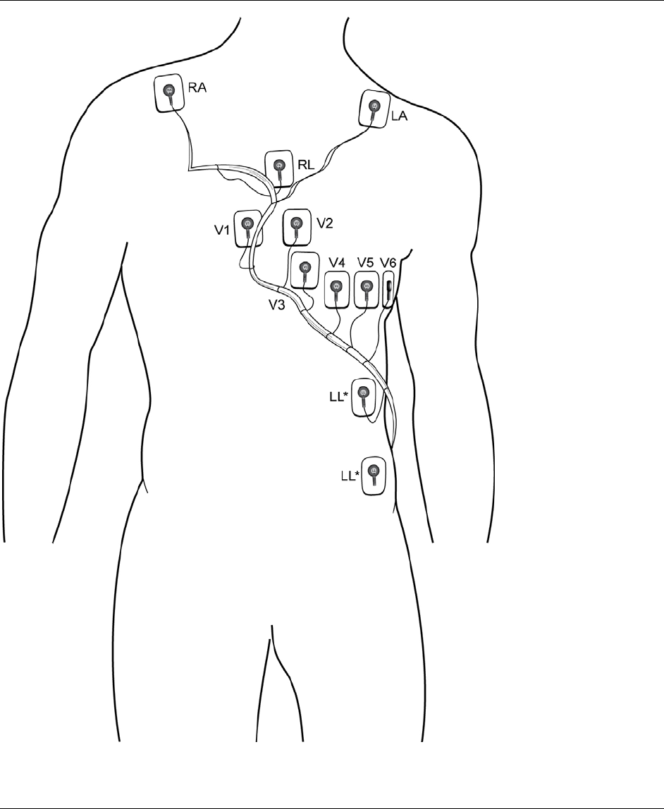
38
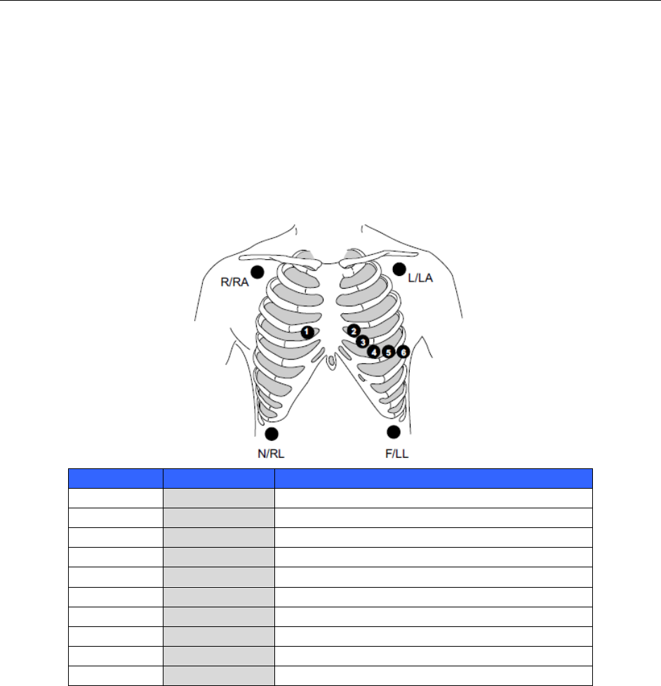
39
Using the LeadForm 12-lead Cable
The 12 Lead SAM may be used for continuous simultaneous monitoring of 12 vectors of ECG. Arrhythmia and ST
analysis on all 12 ECG leads may be performed by the telemetry transmitter when the AM12 is in use.
Refer to the Arrhythmia and ST sections in this manual for further details.
The following diagram describes the recommended electrode placement for using the AM12 in a continuous
monitoring mode.
Figure X: Electrode Locations: Continuous 12-Lead Monitoring
IEC AHA Lead Placement
R (red) RA (white) Just below the right clavicle.
L (yellow) LA (black) Just below the left clavicle.
N (black) RL (green) Lower right edge of the rib cage.
F (green) LL (red) Lower left edge of the rib cage.
C1 (white) V1 (brown) 4th intercostal space, right sternal border.
C2 (yellow) V2 (yellow) 4th intercostal space, left sternal border.
C3 (green) V3 (green) Midway between C2/V2 and C4/V4.
C4 (brown) V4 (blue) 5th intercostal space, mid-clavicular line.
C5 (black) V5 (orange) Left anterior axillary line at C4/V4 level.
C6 (purple) V6 (purple) Mid-axillary line at C4/V4 and C5/V5 levels.
For accurate V-lead placement and monitoring, it is important to locate the 4th intercostal space. The 4th intercostal
space is determined by first locating the 1st intercostal space.
Because patients vary with respect to body shape, it may be difficult to palpate the 1st intercostal space with
accuracy. Thus, locate the 2nd intercostal space by first palpating the little bony prominence called the Angle of
Lewis, where the body of the sternum joins the manubrium.
This rise in the sternum identifies where the second rib is attached, and the space just below it is the 2nd intercostal
space. Palpate and count down the chest until the 4th intercostal space is located.

40
Checking ECG Electrode and Lead Wire Signal Quality
Once the patient has been properly prepared, the electrodes attached and in the correct anatomical location, the
patient ECG cable is connected to the S4 the ECG Display screen display should display the ECG tracing.
Check to ensure the ECG tracing is free of artifact and noise with a clean ECG baseline as per patient condition
permits. If the ECG contains artifact or noise, return to the Hook Up Screen to view lead interface quality and
review the steps for proper electrode site preparation and placement.

41
14. PRODUCT SPECIFICATIONS
General Specifications
Feature Specifications
Instrument Type 12-lead ECG digital transmitter
Input Channels Continuous 12-lead signal acquisition and transmission
ECG Leads Transmitted I, II, III, aVR, aVL, aVF, V1, V2, V3, V4, V5 and V6
Frequency Range 2400.96 MHz to 2482.56 MHz
Special Functions Lead impedance check, ECG display, lead fail, battery notification, multi-purpose call;
10-wire,
Defibrillator Protection Complies with AAMI standards and IEC 60601-2-25
Function Keys Control button; touch screen menu navigation; Internal speaker and microphone
Environmental Conditions
Temperature Operating temperature: +0° to +40° C (+32° to +104° F)
Storage temperature: -20° to +60° C (-4° to +140° F)
Humidity Operating humidity: 15% to 90% RH, non-condensing
Storage humidity: 15% to 95% RH, non-condensing
Altitude Operating: 0 to 4572 m (0 to 15,000’)
Storage: 0 to 12192 m (0 to 40,000’)
Cooling Convection (no fan)
Weight TBD without battery
Dimensions 5.5” x 3.25” x 1.34” (14 x 8.23 x 3.4 mm)
Power Requirements & Battery
Device Classification Type CF, battery operated
Disposable Battery Type Alkaline (3) Batteries Required
Disposable Battery Life 12 Hours minimum
Rechargeable Battery Type Lithium-Ion technology Rechargeable (1) Battery Pack Required
Rechargeable Battery Life 32 Hours minimum
Battery Charging Time TBD

42
Display Specifications
Type High definition, antiglare Color TFT-LCD with LED backlight and resistive touch panel
controls
Size & Resolution 4 inches diagonal; active area; TBD pixels
ECG
ECG 12-Lead ECG with specific Surveyor Acquisition Module (SAM)
Simultaneous Leads Available 12 Lead SAM: I, II, III, aVR, aVL, aVF, V1, V2, V3, V4, V5, V6
Acquisition Rate: 500 samples/sec.
Resolution: 1.17µV
Dynamic Range ± 300mV
ECG Gain (5 mV) 10 mV, 20 mV, 40 mV
Trace Speed (5 mm/sec), 10 mm/sec, 25 mm/sec
CMRR: According to applicable specifications
Pacemaker Spikes
Reject pacemaker spikes shorter than 300 µs.
Detect and report pacemaker spikes up to 2 ms width and amplitudes
Spikes markers will be placed on the sample where the spike is detected
Max. Auxiliary Patient Current: < 10 µA
Frequency Response Filtering: S4 Screen: 0.67 to 40 Hz
Diagnostic at the Central Station: 0.05 to 150 Hz
Input Impedance: >2.5 MOhm at 10 Hz
Electrodes: Must be compatible with EN 60601-2-27
Beat Detection: Sensitivity 99.90%, positive predictivity 99.88% (AHA/MIT database)
Beat Recognition: Normal, Ventricular, Paced, Unknown
HR Averaging
The algorithm calculates the heart rate from its available source.
If the heart rate from the last four R to R intervals is greater than 48 beats per minute, the
average heart rate is determined by averaging the last 16 R to R intervals.
If the heart rate from the last four R to R intervals is less than or equal to 48 beats per
minute, then this rate is used.
Paced beats and PVCs are included in the heart rate calculation.
HR Range: 15 to 300 bpm, Adult and Pediatric
HR Resolution 1 beat per minute
HR Availability: Within TBD seconds after appearance of traces
HR Measurement Accuracy Measurement error (RMS) as measured according to ANSI/AAMI EC57: 2.8% AHA

43
database, 1.7% MIT database
HR Report from the central
station Less than one second. Heart rate is only available when the S4 is connected to the central
station.
Minimum QRS Amplitude: 300µV
Recovery from Defibrillation
Discharge
The worst case device reset and ECG recovery scenario will last less than 5 seconds.
During device recovery a sequence of calibration samples (marked as such) will be
generated and delivered to the central station and S4 display.

44
15. TROUBLESHOOTING
The following table provides guidance for investigating issues that may occur during operation of the S4 telemetry
transmitters. Contact Mortara Technical Service at 1-866-MORTARA for further assistance.
Power and Battery
Symptom Possible Causes Suggested Resolution
The S4 telemetry
transmitter is not working
and display does not light
up.
Internal system failure
Power cycle the S4 telemetry transmitter with fresh
batteries and try again. If problems persist, stop using
the S4 telemetry transmitter and contact Mortara
Technical Support.
Battery will not hold charge Replace the battery according to instructions in the
General Care & Maintenance section.
Display and Touch Screen
Symptom Possible Causes Suggested Resolution
The touch screen is not
working properly. Touch screen failure Power cycle the S4 telemetry transmitter and try again.
If problems persist, stop using the S4 telemetry
transmitter and contact Mortara Technical Support.
The display is not working
properly. Display failure Power cycle the S4 telemetry transmitter and try again.
If problems persist, stop using the S4 telemetry
transmitter and contact Mortara Technical Support.
ECG Trace
Symptom Possible Causes Suggested Resolution
ECG signal is noisy.
Patient movement
Confirm electrode site preparation; confirm correct
ECG placement; instruct the patient to not move.
Calm the patient.
Electrical noise from auxiliary
equipment Isolate the patient from auxiliary equipment, if
possible.
Bad electrode contact
Check to make sure electrodes are still securely
attached to the patient, and reattach if necessary.
Remember the importance of good skin preparation
techniques.

45
16. ACCESSORIES
Use the following Mortara part numbers to obtain spare parts or to reorder accessories:
Part Numbers
Description Part Numbers
S4 SAM 12 LEAD WIRE ACQUISITION MODULE * 76190-002-50
S4 BATTERY DOOR 76190-002-70
LI-ION BATTERY PACK 4800-018
TIE-ON DISPOSABLE POUCH - BOX 100** 8485-029-51
STICK-ON DISPOSABLE POUCH - BOX 100** 8485-030-51
PAT CBL 10WIRE LEADFORM AHA SNAP** 9293-017-50
PAT CBL 10WIRE IEC SNAP CINCH** 9293-017-51
PAT CBL 10WIRE LEADFORM XL AHA SNAP** 9293-026-50
PAT CBL 10WIRE LEADFORM XL AHA SNAP** 9293-026-51
HOOKUP KIT MONITORING 10E SINGLE** 9294-009-50
S4 USER MANUAL 9515-TBD-50-CD
KIT, CHARGER, LI-ION-5, US/CAN 41000-035-01
KIT, CHARGER, LI-ION-5, INTN'L 41000-035-02
KIT, CHARGER, LI-ION-5, AUSTRALIA 41000-035-03
KIT, CHARGER, LI-ION-5, UK 41000-035-04
AC POWER SUPPLY, FOR CHARGER KIT 4101-012
CONVENIENCE TRAY, FOR AA ALKALINE BATTERIES 8364-005-50
* Technical Service Installation Required
** This item is intended for single patient use. It is warranted to be free of defects in workmanship and materials for
a period of 90 days or first use, whichever comes first.
To order additional supplies, contact a Mortara Instrument customer service representative.

APPLIED STANDARDS
46
17. APPLICABLE STANDARDS
•
IEC 60601-1:2012-08 Edition 3.1, Medical Electrical Equipment. Part 1: General Requirements for
basic safety and essential performance.
•
IEC 60601-1-2:2007-03 Edition 3.0, Medical Electrical Equipment – Part 1-2: General
requirements for basic safety and essential performance - Collateral Standard: Electromagnetic
Compatibility – Requirements and tests.
•
IEC 60601-1-6:2010-01 Edition 3.0, Medical Electrical Equipment – Part 1-6: General
Requirements for Safety and Essential Performance – Collateral Standard: Usability.
•
IEC 60601-1-8:2012-1 Edition 2.1, Medical Electrical Equipment – Part 1-8: General
Requirements for Safety and Essential Performance – Collateral Standard: General requirements,
tests, and guidance for alarm systems in medical electrical equipment and medical electrical
systems . (Note: when used in conjunction with the Surveyor Central Station)
•
IEC 60601-2-25:2011-10 Edition 2.0, Medical Electrical Equipment. Part 2-25: Particular
requirements for the basic safety and essential requirements of electrocardiographs.
(Notes: Applies to 10-wire acquisition module only; when used in conjunction with the Surveyor
Central Station))
•
IEC 60601-2-27:2011-08 Edition 3.0, Medical Electrical Equipment. Part 2-27: Particular
requirements for the basic safety and essential performance of electrocardiographic monitoring
equipment.
(Notes: Applies to 3-wire/5-wire acquisition module only; when used in conjunction with Surveyor
Central Station )
•
IEC 60529:2001-02, Degrees of protection provided by enclosures (IP Code), Edition 2.1.
•
IEC 62366:2007-10 Edition 1.0, Medical devices – Application of usability engineering to medical
devices.
•
ETSI EN 301 489 –1:2011-09 v1.9.2, Electromagnetic compatibility and Radio Spectrum Matters,
Part1: Common technical requirements
•
ETSI EN 301 489 –17:2012-09 v2.2.1, Electromagnetic compatibility and Radio Spectrum
Matters, Part17: Specific conditions for Broadband Data Transmissions Systems

47
•
ETSI EN 300 328:2006-10 v1.7.1, Electromagnetic compatibility and Radio Spectrum Matters,
Wideband transmission systems; Data transmission equipment operating in the 2.4 GHz ISM band
and using wide band modulation techniques
•
ISO10993-1:1997-12-15, 2nd Edition, ISO10993-5: 1995-05-15, 2nd Edition, ISO10993-10: 2002-
09-01, 2nd Edition + AM1: Biological evaluation of medical devices, Part 1, Part 5, and Part 10 for
in vitro cytotoxicity, irritation, and delayed-type hypersensitivity.
•
21 CFR Part 820, FDA Quality System Regulation (QSR)
•
Part 15 of the FCC rules.
•
93/42/EEC: Council Directive of 14 June 1993 concerning medical devices. (Medical Device
Directive)
•
99/5/EC: Council Directive on radio equipment and telecommunications terminal equipment and
the mutual recognition of their conformity. (R & TTE Directive)
•
2002/96/EC:2003, Waste Electrical and Electronic Equipment
•
2002/95/EC:2003, Restriction of the use of Certain Hazardous Substances in Electrical and
Electronic Equipment
•
EC No 1907/2006, Registration, Evaluation, Authorization and Restriction of Chemicals (REACH)
•
Canadian Medical Device Regulation (MDR)