TAKAYA TR3-C202-A0-8 RFID Reader/Writer User Manual Manual
TAKAYA Corporation RFID Reader/Writer Manual
UserManual.wiki
>
TAKAYA
>
TR3-C202-A0-8 User Manual
>
Manual
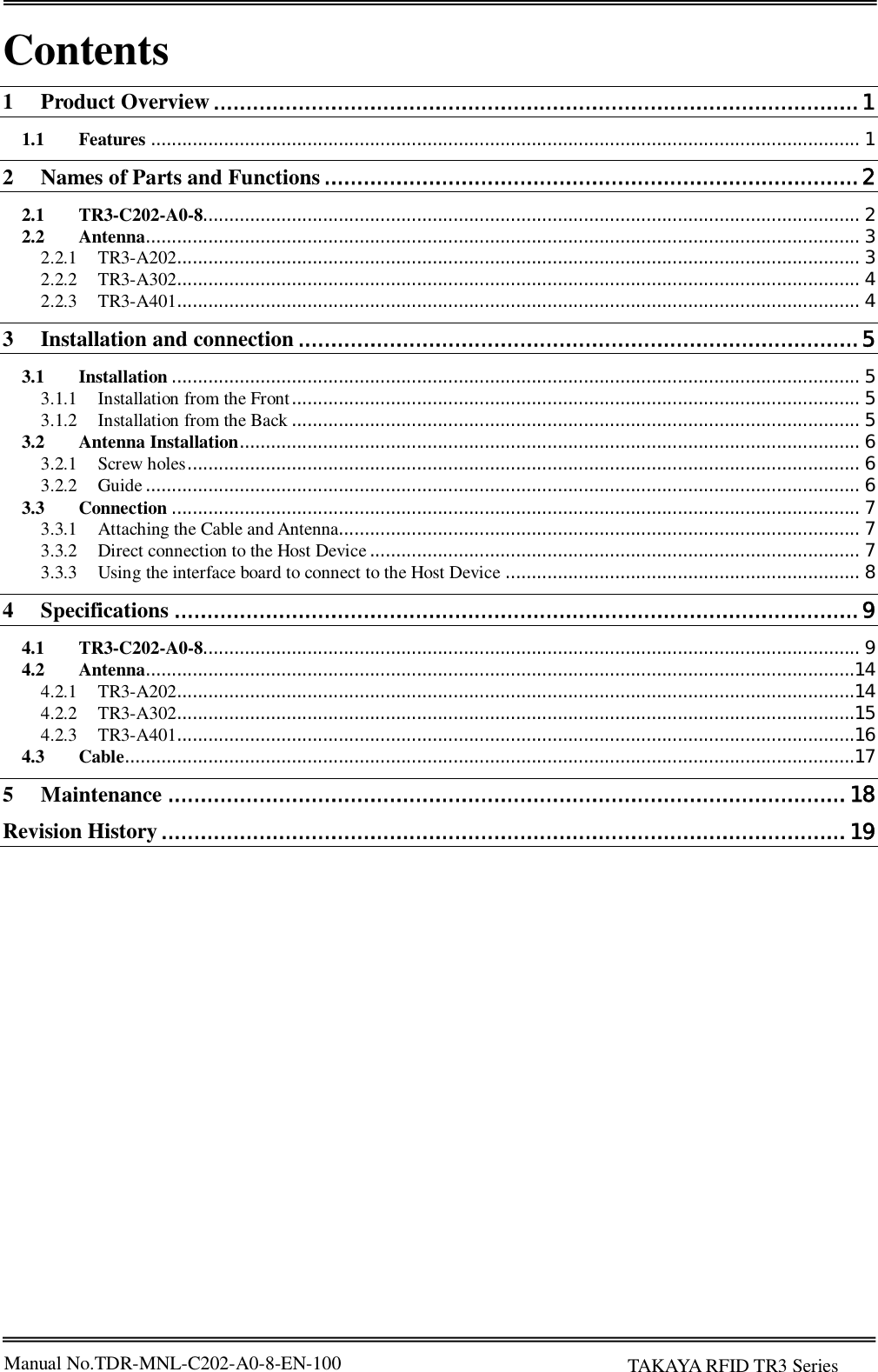
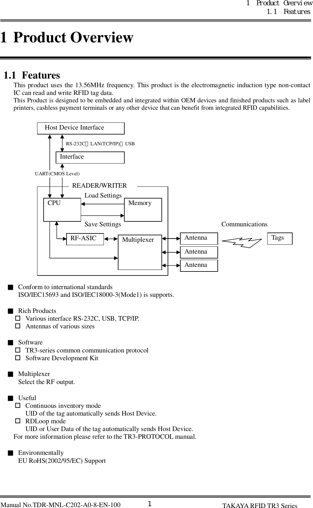
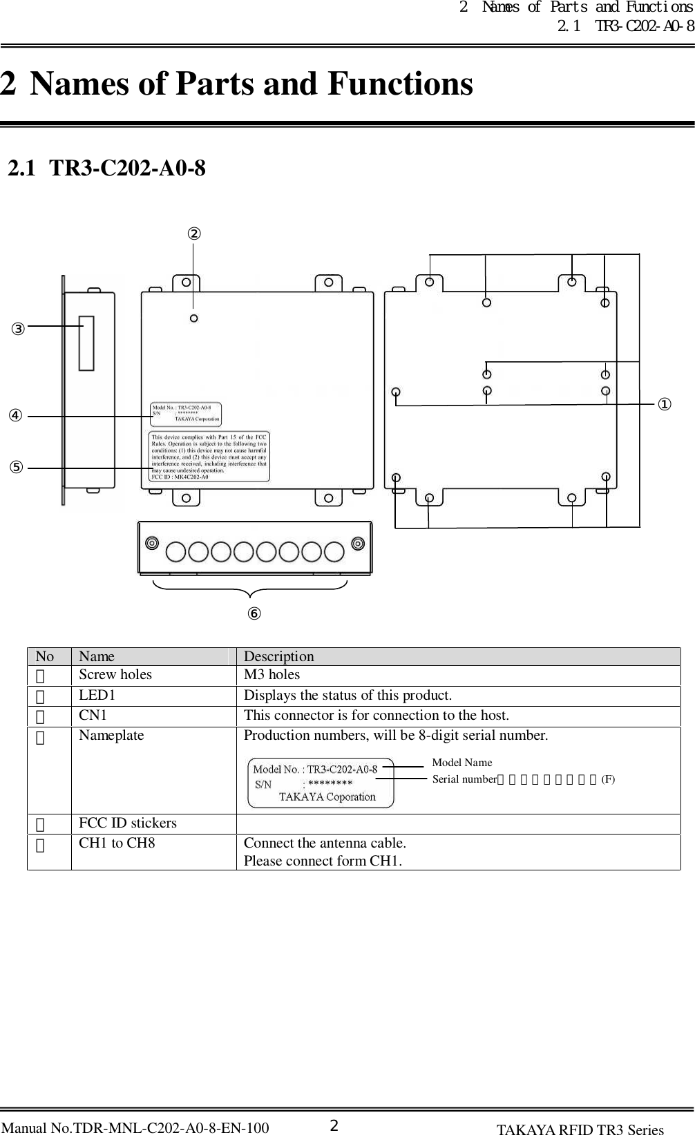
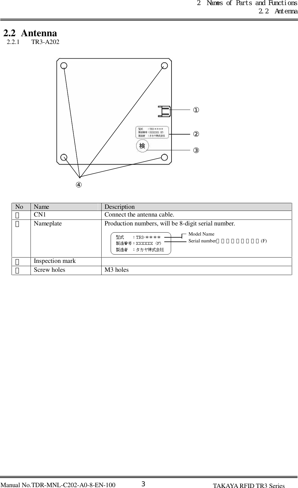
Contents
1.
Manual
2.
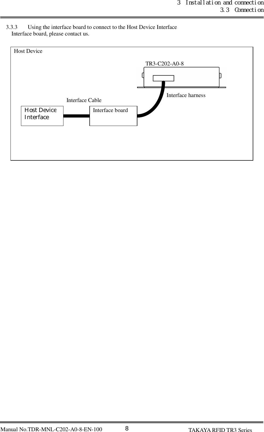
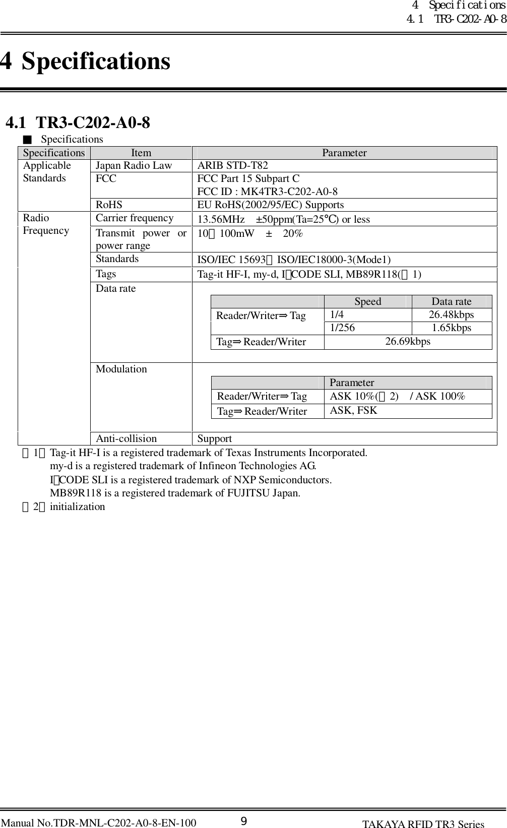
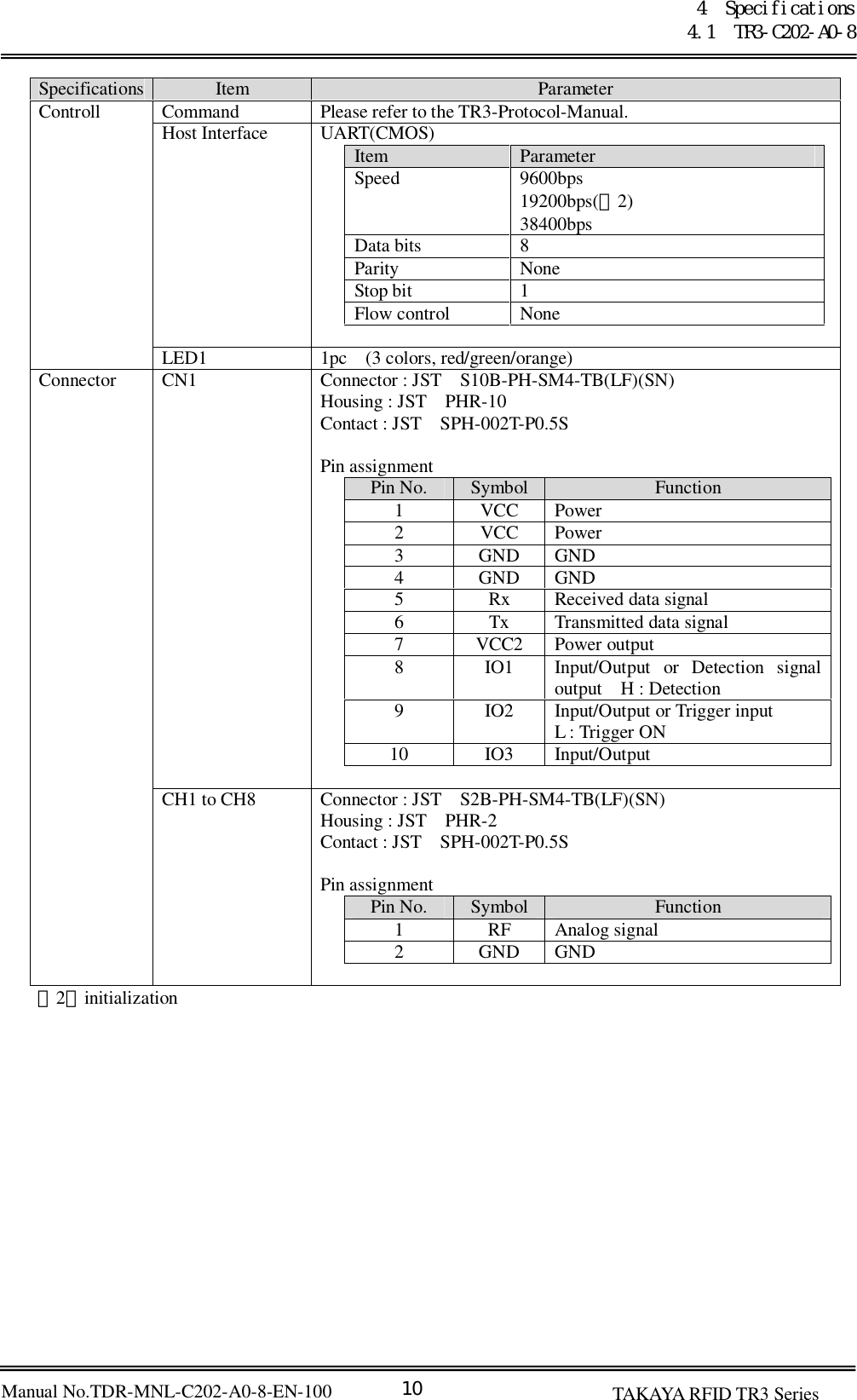
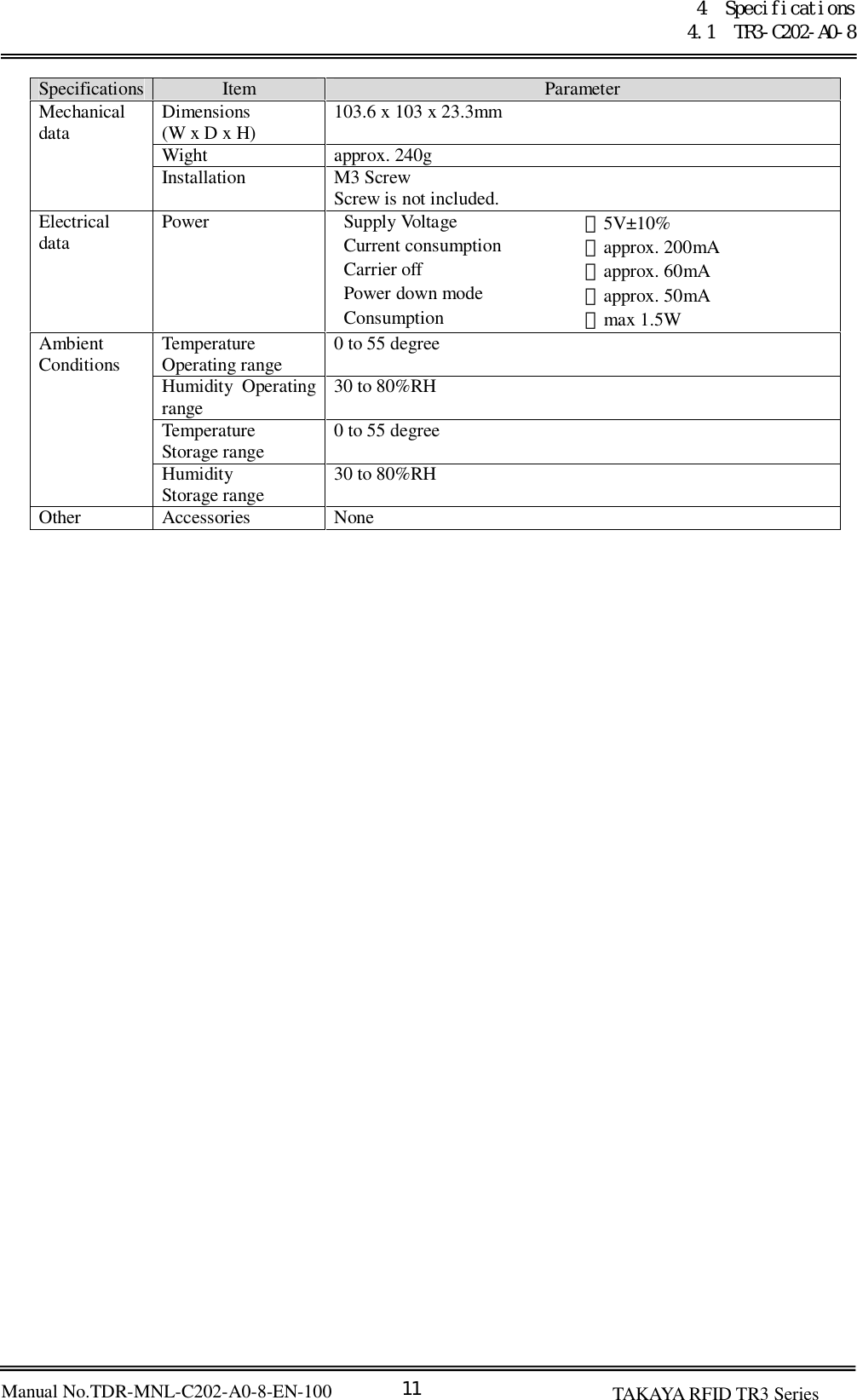
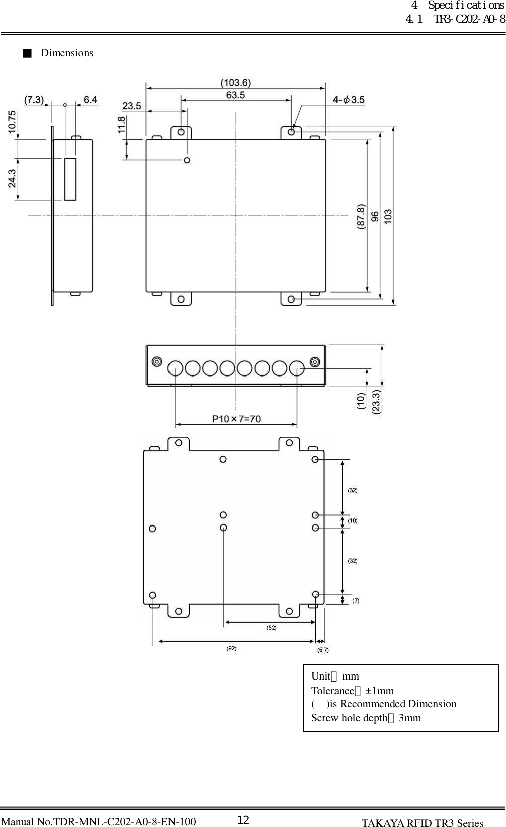
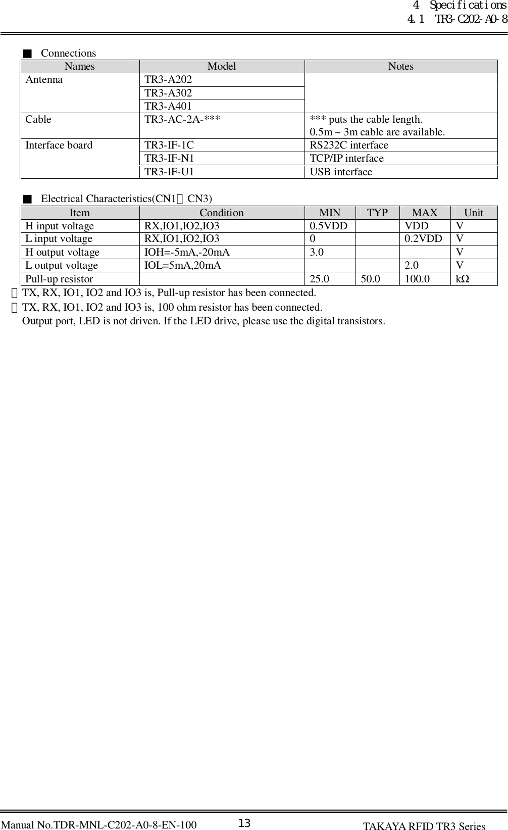
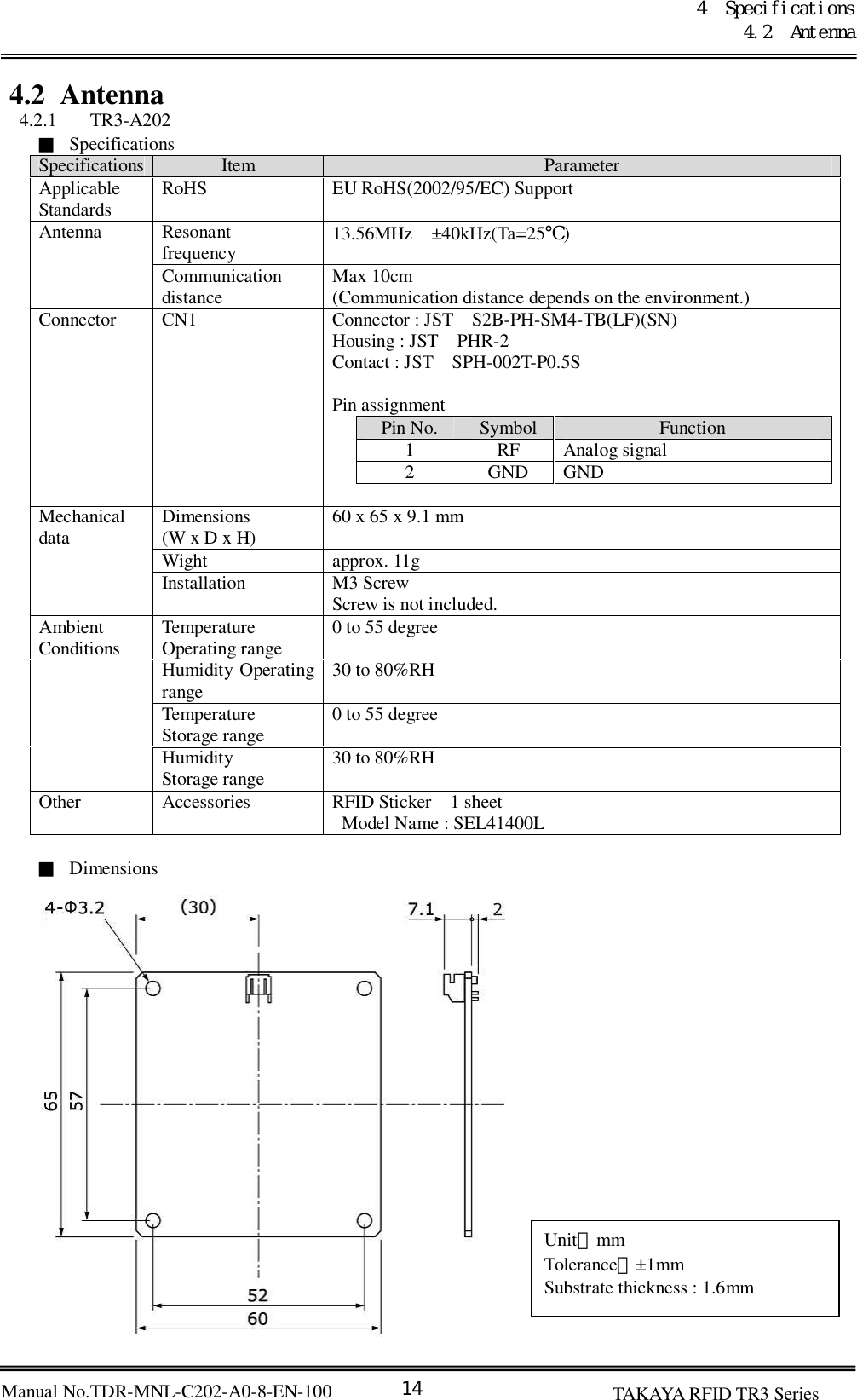
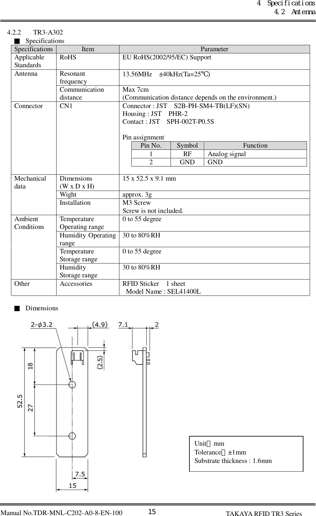
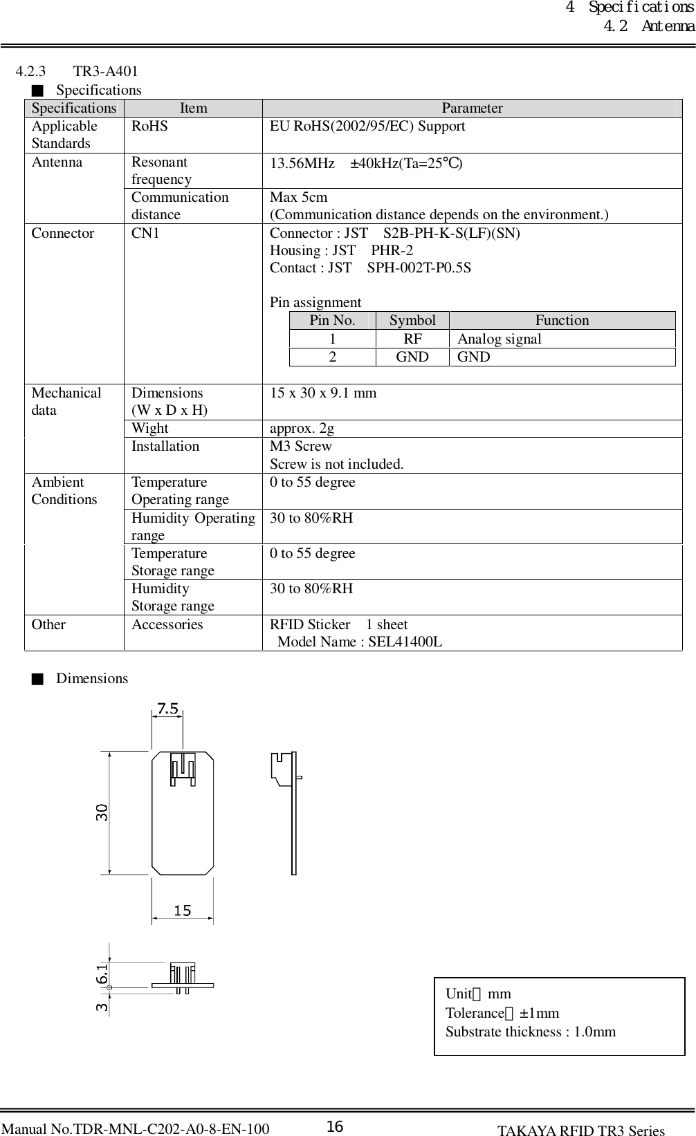
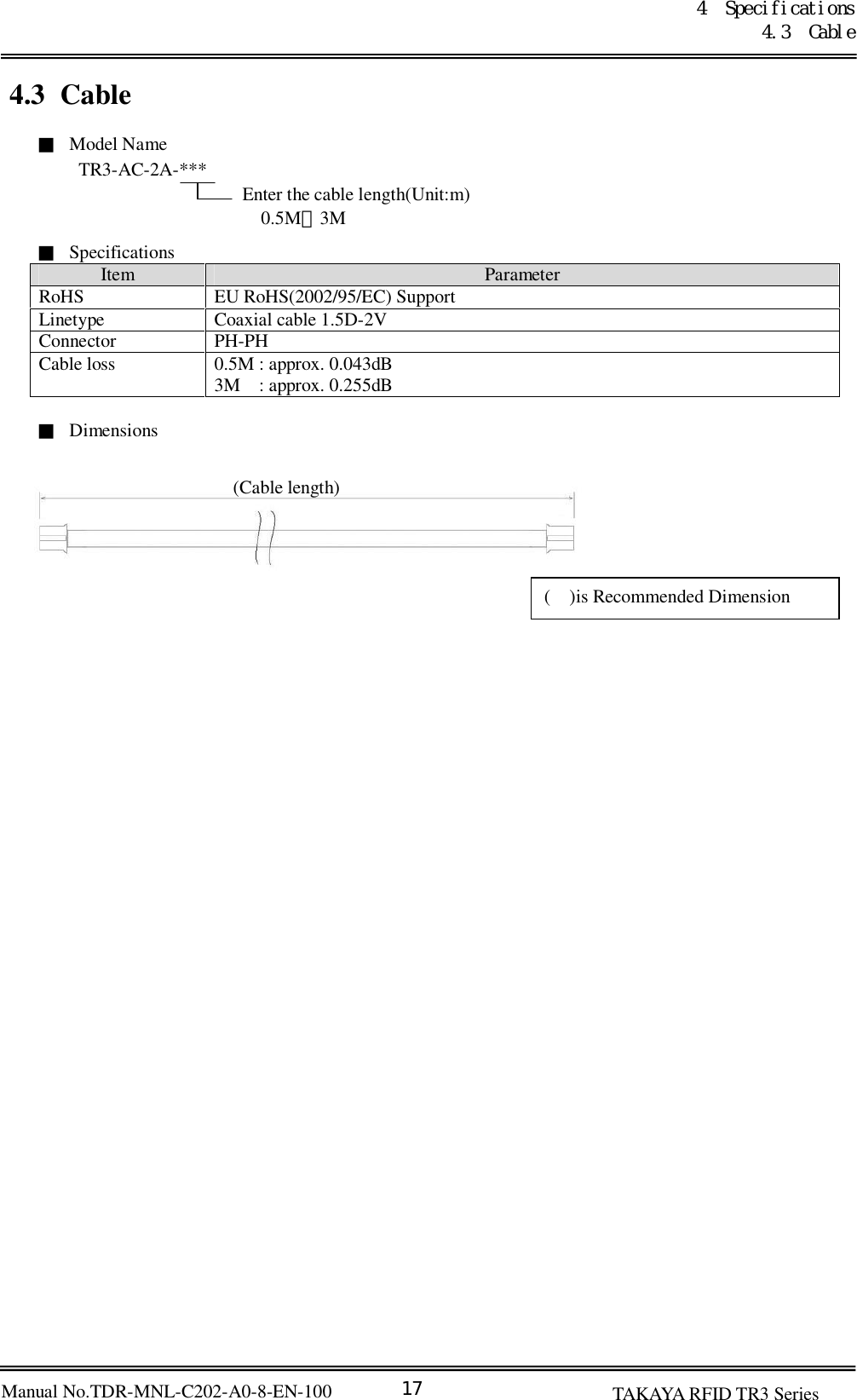
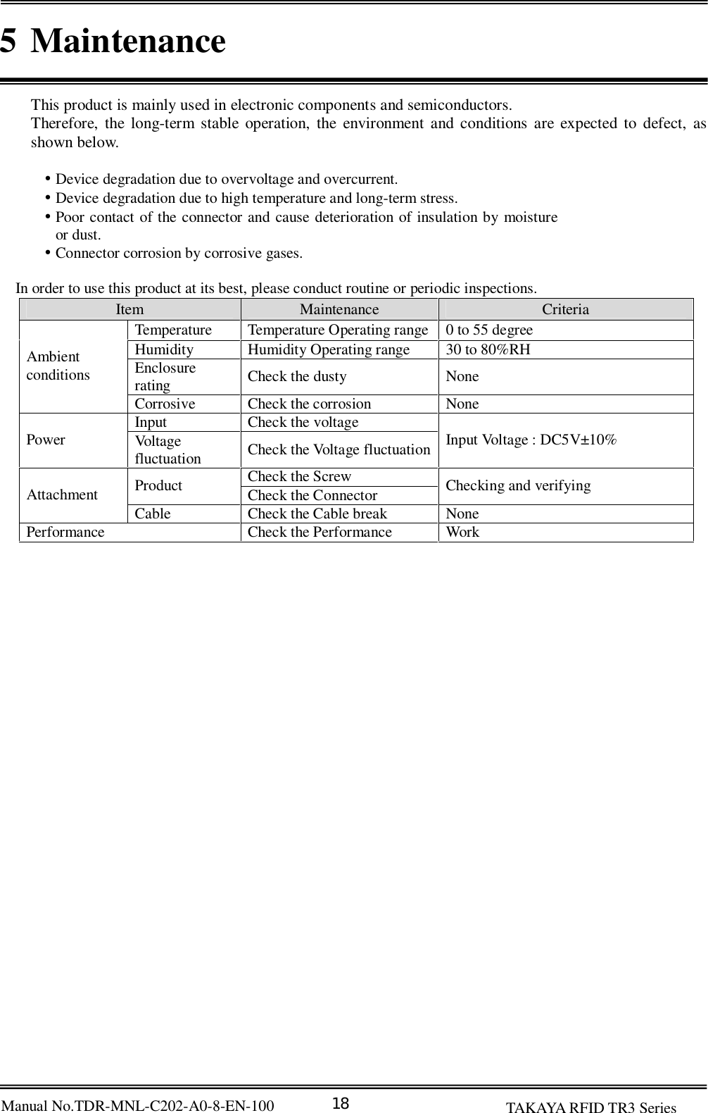
User Manual
Manual
Navigation menu
Upload a User Manual
Namespaces
Wiki Guide
HTML
PDF
Info
Views
User Manual
Discussion / Help
Navigation
![20 [URL] http://www.takaya.co.jp/ [Mail] rfid@takaya.co.jp](https://usermanual.wiki/TAKAYA/TR3-C202-A0-8.Manual/User-Guide-1277355-Page-25.png)