TCITY ELECTRONICS TC88 TPMS User Manual
SHENZHEN TCITY ELECTRONICS CO.,LTD TPMS Users Manual
User Manual
Monitor Feature
·Automatically solar power battery recharger.
·pressure and temperature alarm.
·Visible and audible alarm.
·Selectable pressure unit(PSI,BAR).
·Selectable pressure unit(℃,℉).
·Configurable high/low pressure and high temperature alarm.
·Tire position exchange.
·Automatic awake feature.
·Automatic backlighting.
·Built in rechargeable lithium battery.
·Monitor up to 7 tires(including one spare tire).
·Display temperature and pressure simultaneously.
·Fast leakage alert.
·High stability and easy to install.
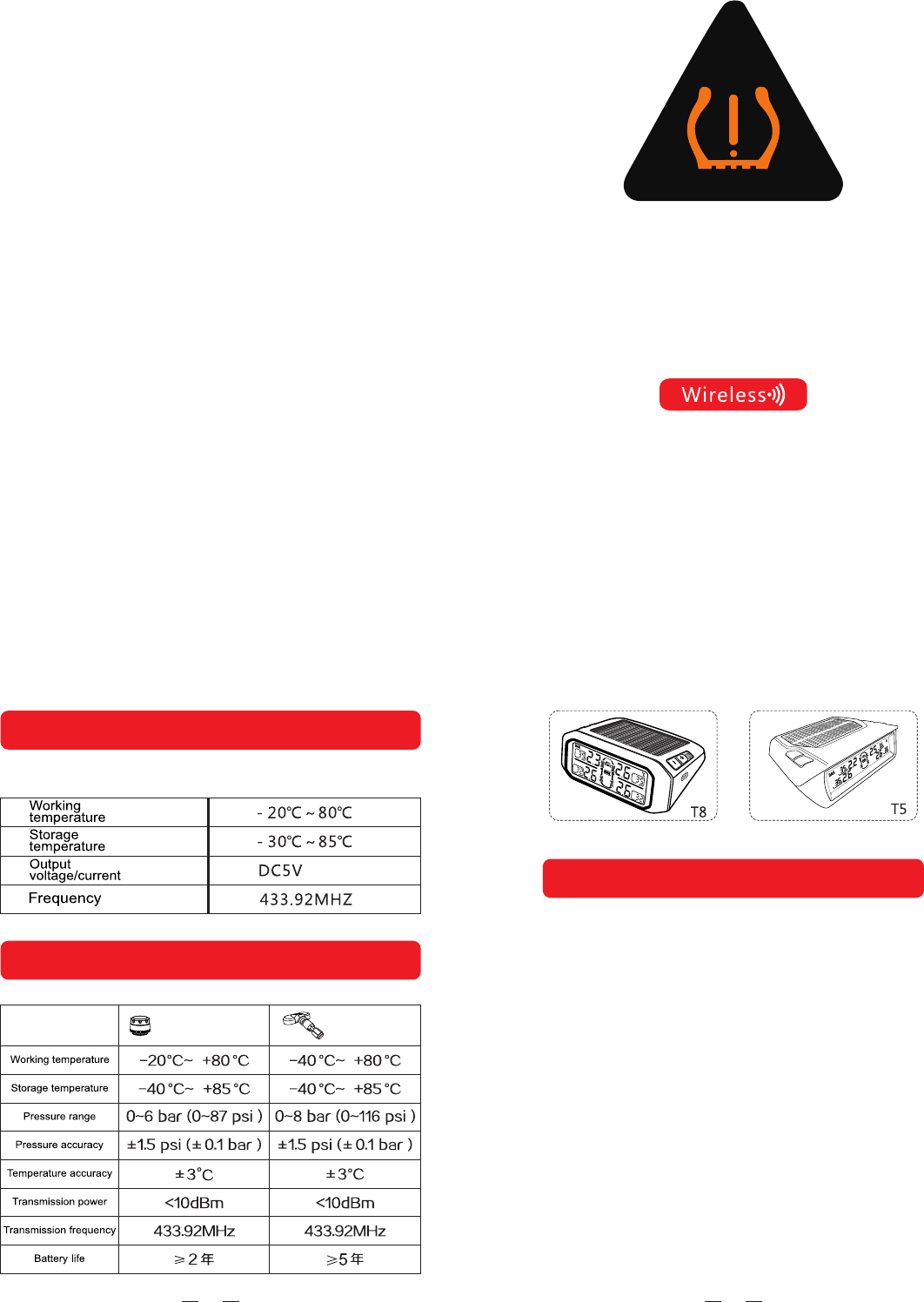
Remark:The photo only for referance,configure according to
the type that you selected
Function button using according to the actual machine
010112
Monitor Specification
Sensor Specification
sensor sensor
Instruction Manual
Tire Pressure Monitoring System
13
1.Please use system correctly in the right condition. The distributor
is not liable fordamages form the miss-use.
2.Installation should follow the instruction guide,if any damage
occurs due to thewrong installation,the distributor is not liable
for it.The content and specification are subject tochange
without prior notice.Pictures in the article are just for
illustration.
3.Please take the actual product for reference.Internal sensor
installation should be carried out by professional person. Be
wareof the internal sensorswhile reload the tire.
4.Please be careful not to damage the
sensor during the removal
02
Installation Tips
Monitor should be installed in appropriate place using the sticky
padorthe magic tape. Recharge the monitor by theDC-DC power
adaptor forfirst time and allow continue recharge by solar power
after the firstfull DC recharge
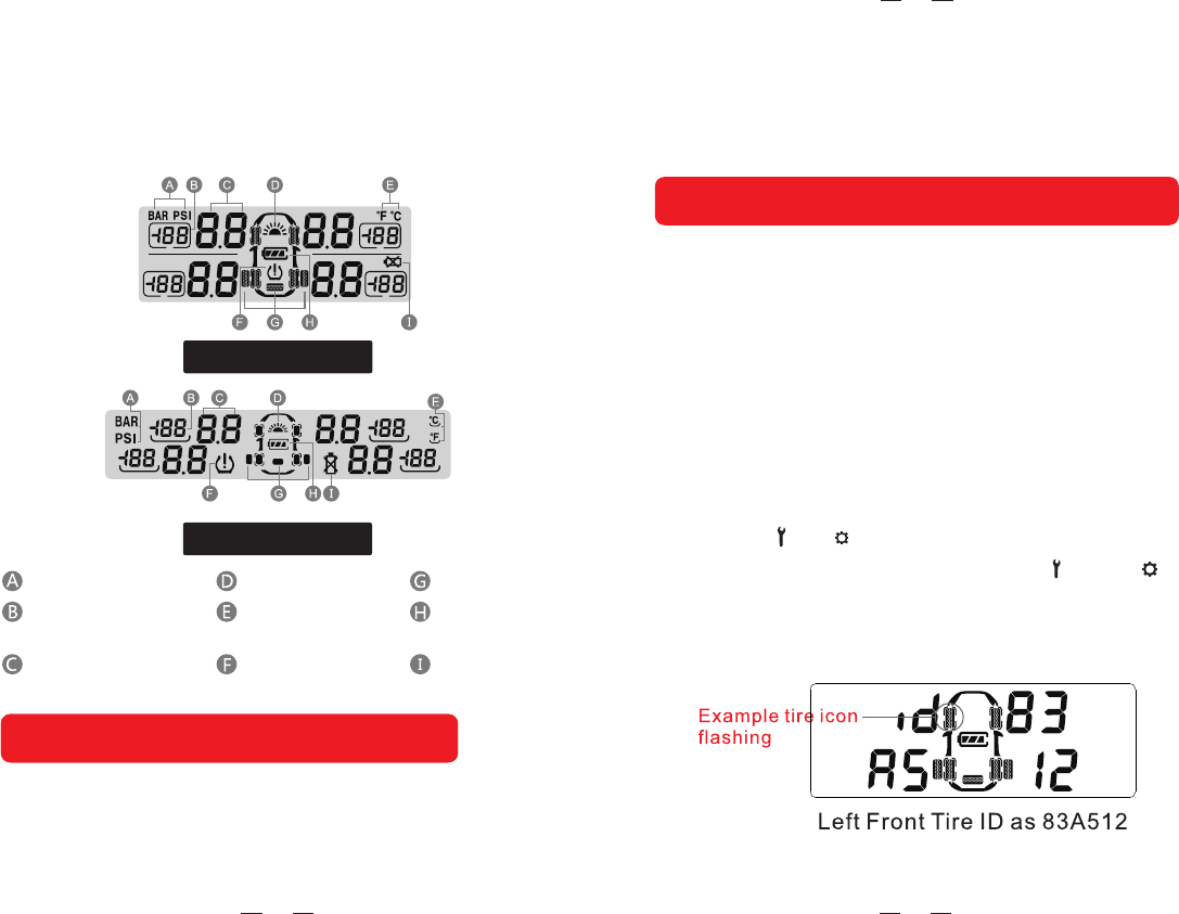
T6、T8、T9 Display
T5 Display
Pressure unit
The tire temperature
numerical display
The tire pressure
numerical display
Solar charging icon
Temperature of
the unit
The alarm icon
Spare tire icon
Power display
Sensor low
electric icon
Installation TipsInstallation Tips
11
in standby mode, press and hold “+”button andreleaseit after
the beep sound toenter learning mode ,the tire iconwill flash on
the LCD with “Id”Letter showing the beginning letter of the tire
ID code. Short press “-”or “+”to scroll tire position needed to
re-code.Once ready, then mount the sensor on to the tire valve
(for externalsensor),or inflate the tire(for internal sensor),once
the sensor sensed the inflator,the sensorwill send its own ID
code to the monitor and the monitor willdisplay itʼssensor code
after the beep. Repeat above step to re-code others sensor if
needed.Press“ ”or “ ”until Beep sound to ensure new code
completed stored intothe monitor.if press “ +” “ ” or “+” “ ”
buttons together will not store any new ID and resumeto
standby mode.
Inflate Code Learnings
03
Press the button “+” and “ ” or “+” and “ ” at the same time
to exit without saving the setting. The monitor will return to stand
by mode if there is no operation within 1 min in the setting mode.
In standby mode,press the “ ” or “ ” button,releaseafter the
1 beep to enter the 1 set up menu. The corresponding icon
on the LCD will flash. Press the “ ” or “ ” button to select the
desired setting, press button “+”or “-” to select the data. After
the setting is finished , press the “ ” or “ ” button to save the
setting and exit after a beep.
st st
Parameters Settings
Setting Sequence
1.Pressure Unit
While the PSI or BAR iconis flashing ,press the button
“+”or“-”to select the desired unit.
10
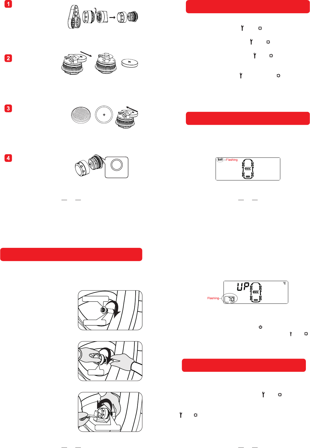
Remove battery
from battery
holder
Replace new lithium
battery ,ensure
positive“+”is
facing upwards
Remount plastic enclosure
using the fixture provided
in counter clockwise
direction
Use fixture provided
inside package and
open the plastic
enclosure in counter
clockwise direction
Rubber
o-ring
05
First turn off the monitor by pressing“ ” ,then turn on the monitor
again until all icons displayed and press the button“ ”or “ “within
3 seconds,release after a“ Bi ”sound will light to complete factory
reset.
5.High Temperayure Setting
While the high temperature data and all tire icons
Are flashing ,press the button “+”or“-”to set the
Desired temperature data .
To restore the factory default setting:
Tire position exchange
During standby mode, long press “-”until “BI” sound to begin,
one tire will flash and use “ + ”or “ - ” to exchange to a new
tire position and confirm by pressing “ ” or “ ” button Repeat
using “-” to choose another tire and follow by using“+”or “-”
button to exchange another new tire and finished by pressing
“ ” or “ ” buttonagain with a long beep.(During ID interchange
mode if no action for one minte, systemwill resume to normal
mode operation)
08
Hex nut
Air Valve
Sensor
Hex nut
sensor installation
Tips:piease ensure to turn on the monitor firsely before install
the sensor so that the monitor can receive the sensor data on
time.
Mount the hex nuts
Screw in sensor at clock
wise direction
Tidhten hex nuts in counter
clock wise Direction
04
2.Temperature Unit
While the ℃ or ℉ icon isflashing ,press the button
“+”or “-” to select thedesired unit.
3.High Pressure Setting for
Front Tires
While the two front tire icons and the high pressuredata
icons are flashing ,press the button“+”or“ - ”to select
the desired pressure data.
4.Low Pressure Setting for
Front Tires
While the two fornt tire icons and the low pressure
data icons are flashing ,press the button “+”or“-”
to select the desired pressure data .
06
First turn off the monitor by pressing“ ” ,then turn on the monitor
again until all icons displayed and press the button“ ”or “ “within
3 seconds,release after a“ Bi ”sound will light to complete factory
reset.
5.High Temperayure Setting
While the high temperature data and all tire icons
Are flashing ,press the button “+”or“-”to set the
Desired temperature data .
To restore the factory default setting:
Tire position exchange
During standby mode, long press “-”until “BI” sound to begin,
one tire will flash and use “ + ”or “ - ” to exchange to a new
tire position and confirm by pressing “ ” or “ ” button Repeat
using “-” to choose another tire and follow by using“+”or “-”
button to exchange another new tire and finished by pressing
“ ” or “ ” buttonagain with a long beep.(During ID interchange
mode if no action for one minte, systemwill resume to normal
mode operation)
07
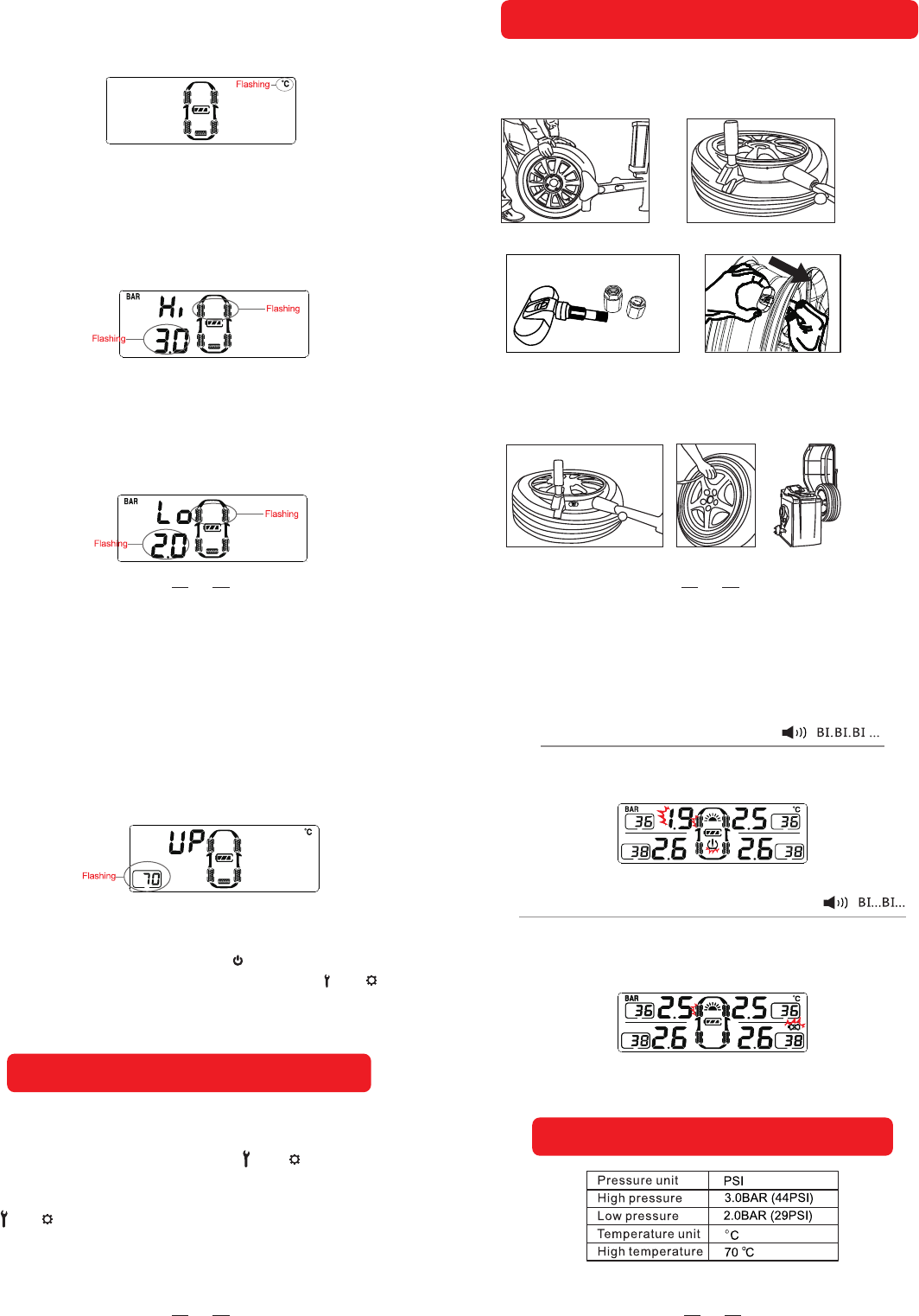
Fast Leakage Alert
The sensor will send alert data to the monitor if it detects
fast leakage in a tire. The alert icon and the pressure data
will flash together with the tire icon.
Sensor Low Batter Alert
While the sensor battery voltage is low, the sensor will send
the alert to themonitor . The corresponding tire icon and the
low battery icon
Factory default alarm setting
09
(2) Use tire changers to demount the tire and remove the
original valve.
(3) Take out the Ring ,Nut ,Vale Cover of the sensor.
internal sensor installation
(1) Unload the from the vehicle and deflate the tire.
(4) Use the specified spanner to loose the sensor’s valve firstly, put the
sensor to the wheel hub and using hand to adjust the best installation
position and tighten the sensor valve, and then take out the sensor and
using the specified spanner to tighten the sensor again.
FCC Statement
This equipment has been tested and found to comply with the limits for a Class B
digital device, pursuant to part 15 of the FCC rules. These limits are designed to
provide reasonable protection against harmful interference in a residential installation.
This equipment generates, uses and can radiate radio frequency energy and, if not
installed and used in accordance with the instructions, may cause harmful interference
to radio communications. However, there is no guarantee that interference will not
occur in a particular installation. If this equipment does cause harmful interference to
radio or television reception, which can be determined by turning the equipment off
and on, the user is encouraged to try to correct the interference by one or more of the
following measures:
-Reorient or relocate the receiving antenna.
-Increase the separation between the equipment and receiver.
-Connect the equipment into an outlet on a circuit different from that to which the
receiver is connected.
-Consult the dealer or an experienced radio/TV technician for help.
To assure continued compliance, any changes or modifications not expressly
approved by the party.
Responsible for compliance could void the user’s authority to operate this
equipment. (Example- use only shielded interface cables when connecting to
computer or peripheral devices).
This equipment complies with Part 15 of the FCC Rules. Operation is subject to
the following two conditions:
(1) This device may not cause harmful interference, and
(2) This device must accept any interference received, including interference that
may cause undesired operation.