TCL Delonghi Home Appliances 5005HBS 802.11 b/g/n Wifi module User Manual
TCL Delonghi Home Appliances (zhongshan) Co., Ltd. 802.11 b/g/n Wifi module
User Manual

BroadLink 5005-HBS Wi-Fi Module
Datasheet
1. Introduction
1.1 Overview
The 5005-HBS is a highly integrated Wi-Fi module, which supportsIEEE802.11b/g/n single stream,
providing GPIO for intelligent control, and UART interfaces for device communication.
The 5005-HBS has 8Mbits flash and integrates power amplifier, low noise amplifier, and RF switch to
reduce the module size and RF design capability required.
The 5005-HBS embedded ARM Cortex-M4F MCU, the Frequency could reach 200MHz, 512KB SRAM
and 8Mbits Flash are included.
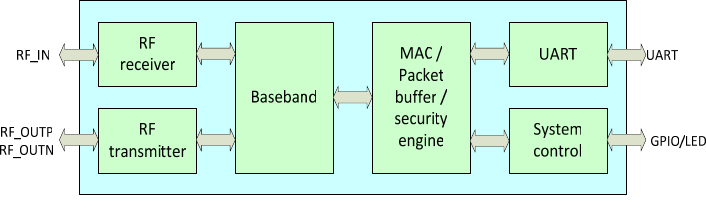
5005-HBS block diagram
1.2 Applications
Smart home appliances
Remote Control
Medical/Health Care
Network consumer devices
1.3 Key Features
Single operation voltage: 5V
Power consumption: 80mA for IDLE mode and 1.1mA for Sleep mode
Wi-Fi connectivity
802.11b, 802.11g, 802.11n (single stream) on channel 1-11@2.4GHz
WPA/WPA2 Enterprise
Transmit power: 16dBm@11b, 14dBm@11g,13dBm@11n
Receiver Sensitivity: <-78dBm (802.11b 11Mbs),<-68 dBm (802.11g 54Mbs), <-66dBm
(802.11n MCS7)
Max Data rate: 11Mbps@11b,54Mbps@11g, MCS7@11n HT20
Wi-Fi modes: Station and AP
Patent SmartConfig™ technology
On-board PCB antenna, IPEX connector for external antenna
Operating Temperature: -10 ℃ to 70 ℃
1.4 Channels
802.11b, 802.11g, 802.11n(20MHz): 11
Working Frequency of Each Channel:
channel Frequency channel Frequency
1 2412 7 2442
2 2417 8 2447
3 2422 9 2452
4 2427 10 2457
5 2432 11 2462
6 2437
2. Product Overview
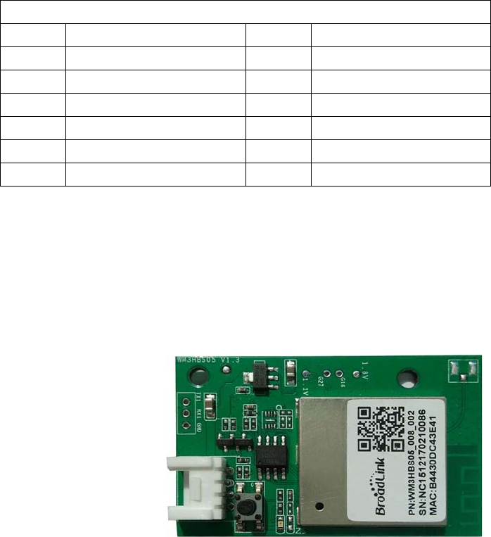
2.1 Product Picture
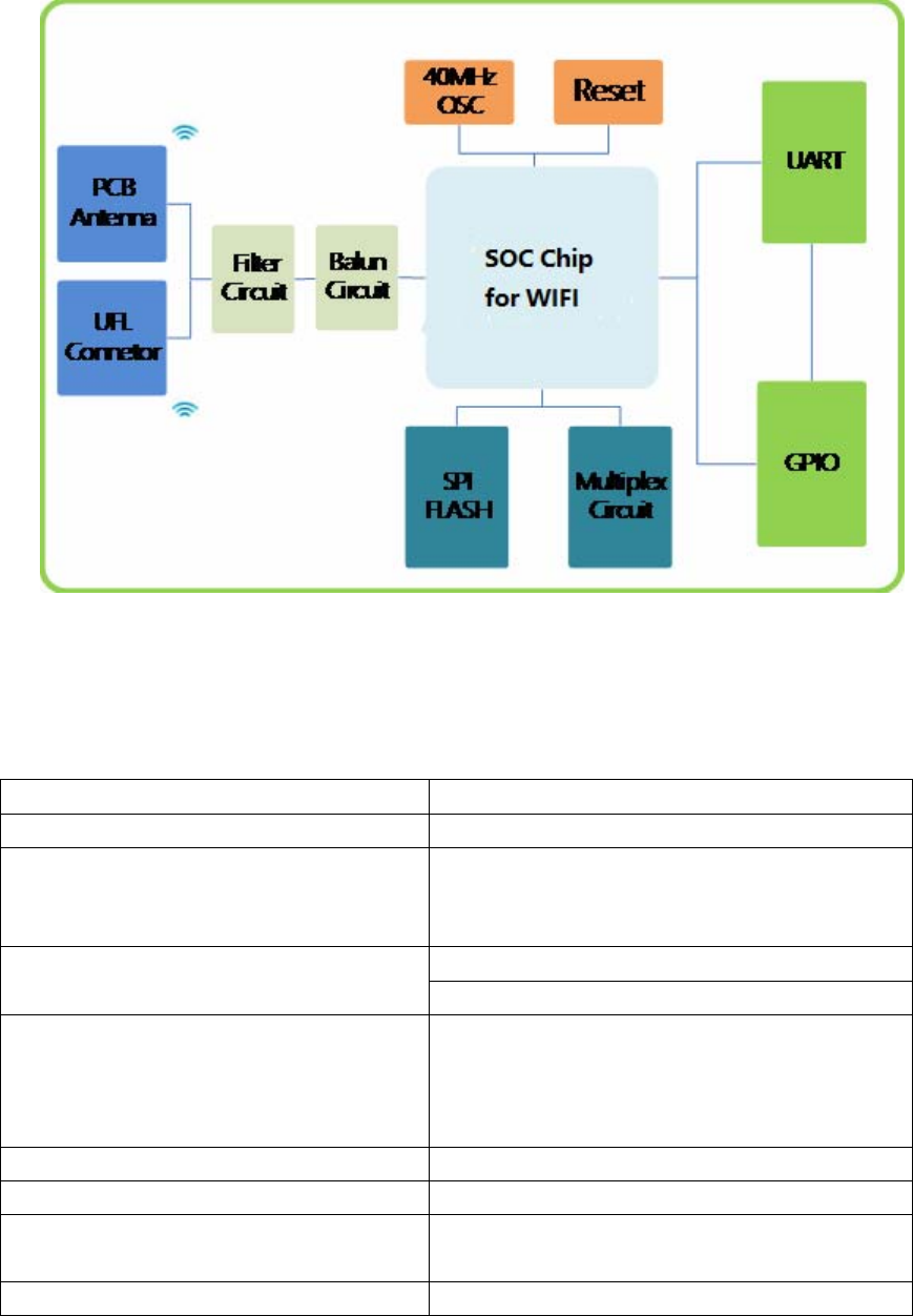
2.2 Block Diagram
3. Electrical Characteristics
3.1 WLAN Parameter
FrequencyRange2.412GHz‐2.462GHz
WirelessStandardIEEE802.11b/g/n
OutputPower
802.11b:16dBm
802.11g:15dBm
802.11n:15dBm
PCBprintedANT
Antenna
IPEXconnectorforexternalantenna
InputLevelSensitivity
802.11b<‐90dBm@1Mbps
802.11b<‐80dBm@11Mbps
802.11g<‐88dBm@6Mbps
802.11g<‐70dBm@54Mbps
ProtocolStackIPv4,TCP/UDP/FTP/HTTP/HTTPS/TLS/mDNS
DataRate11M@802.11b,54M@802.11g,MCS7@802.11n
Securitydataencryptionstandard:WEP/WEPA/WPA2
encryptionalgorithm:WEP64/WEP128/TKIP/AES
NetworkTypeSTA/AP/STA+AP/WIFIDirect
3.2 Absolute Maximum Ratings
SymbolDescriptionMin.Max.Units
TsStoragetemperature‐40125℃
TAAmbientoperating ‐2085℃
temperature
3.3 DC Voltage and Current
SpecificationsMin.Typ.Max.Units
VDD4.555.5V
VIL(inputlowvoltage)‐0.4 0.7V
VIH(inputhighvoltage)0.7*VDD VDD+0.4V
VOL(outputlowvoltage)‐0.4 0.3*VDDV
VOH(outputhighvoltage)0.7*VDD VDD+0.4V
Standby60 mA
pulsecurrent@TX
11b@16dBm11Mbps
350 mA
pulsecurrent@TX
11g@14dBm54Mbps
350 mA
3.4 IEEE802.11b Mode
ITEMSpecification
ModulationType
DSSS/CCK
Frequencyrange2412MHz~2462MHz
Channel
CH1toCH11
Datarate
1,2,5.5,11Mbps
TXCharacteristics
Min
Typical
Max.
Unit
TransmitterOutputPower
11bTargetPower16dBm
FrequencyError‐20+20ppm
ConstellationError(peakEVM)@targetpower
1~11Mbps
‐28‐26
RXCharacteristics
Min
Typical
Max.
Unit
MinimumInputLevelSensitivity
1Mbps(FER
≦
8%)
‐95dBm
11Mbps(FER
≦
8%)‐84dBm
MaximumInputLevel
(FER
≦
8%)
‐10
dBm
3.5 IEEE802.11g Mode
ITEMSpecification
ModulationType
OFDM
Frequencyrange2412MHz~2462MHz
ChannelCH1toCH11
Datarate
6,9,12,18,24,36,48,54Mbps
TXCharacteristics
Min
Typical
Max.
Unit
TransmitterOutputPower
11gTargetPower14dBm
FrequencyError‐20+20ppm
ConstellationError(peakEVM)@targetpower
6Mbps ‐21dB
54Mbps ‐31dB
Transmitspectrummask
@11MHz
‐20
dBr
@20MHz
‐28
dBr
@30MHz ‐40dBr
RXCharacteristics
Min
Typical
Max.
Unit
MinimumInputLevelSensitivity
6Mbps
‐90dBm
54Mbps‐72dBm
MaximumInputLevel
(FER
≦
10%)
‐20
dBm

3.6 IEEE802.11n 20MHz Bandwidth Mode
ITEMSpecification
ModulationType
OFDM
Frequencyrange2412MHz~2462MHz
ChannelCH1toCH11
Datarate
M C S 0 /1/2/3/4/5/6/7
TXCharacteristics
Min
Typical
Max.
Unit
TransmitterOutputPower
11nHT20Tar getPower13dBm
FrequencyError‐20+20ppm
ConstellationError(peakEVM)@targetpower
MCS0 ‐19dB
MCS7 ‐30dB
Transmitspectrummask
@11MHz
‐20
dBr
@20MHz
‐28
dBr
@30MHz
‐40dBr
RXCharacteristics
Min
Typical
Max.
Unit
MinimumInputLevelSensitivity
MCS0
‐90dBm
MCS7
‐72dBm
MaximumInputLevel
(FER
≦
10%)
‐20
dBm
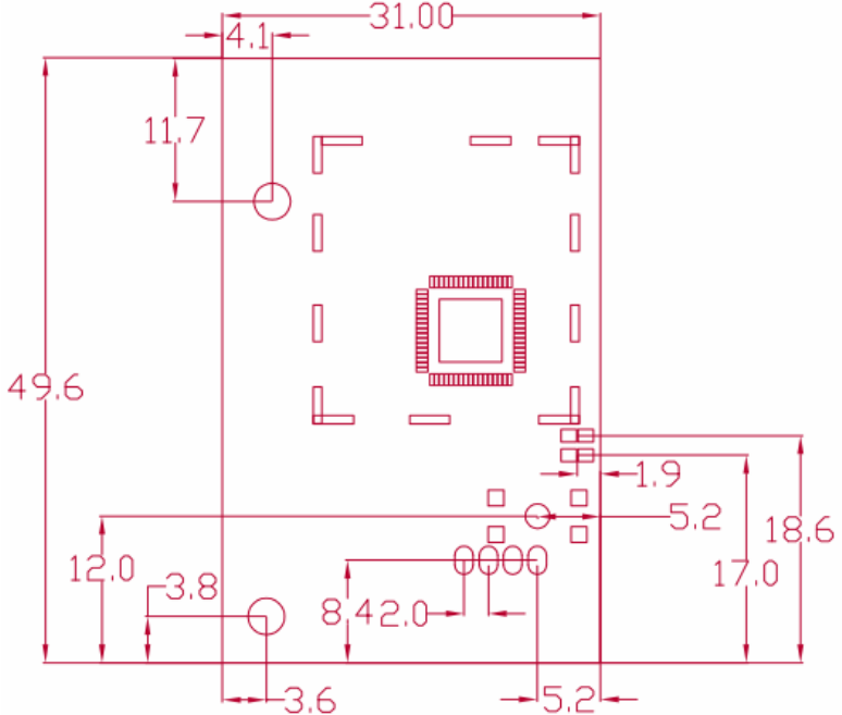
4. Mechanical Characteristics
5005-HBS has 4 pins. The layout of PINs is shown in the figure below.
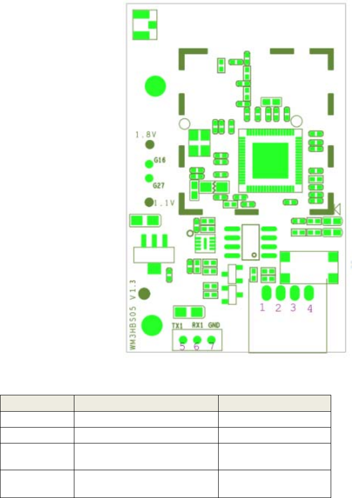
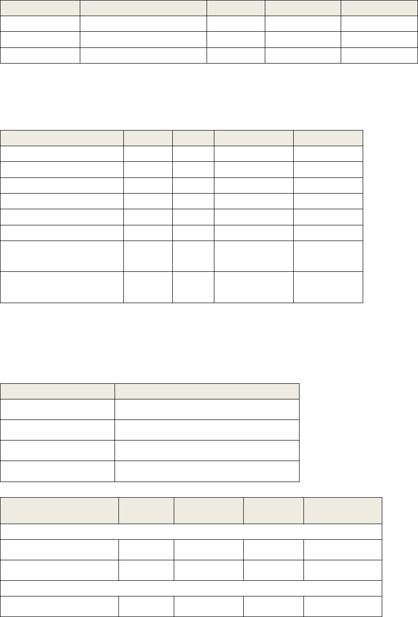
4.1 PIN Definitions
Pins Pin Assignment Notes
Pin1
VCC
5V
Pin2
GND
Ground
Pin3
UART_TX_5V
UART
transmitterPin
Pin4
UART_RX_5V
UARTReceiver
Pin
1. TX and RX of UART0 are used to communicate with peripheral processor using power source
of 5V. Its output voltage level refers to the description in chapter 3.3 DC characteristics。
2. The 5005-HBS contains RC (resistance- capacitance) and WATCHDOG. Users also can use
their RESET circuit.
3. The WIFI indicator LED is embedded in the module.
4. Press the reset button for more than 5 seconds, the module would be resettled,
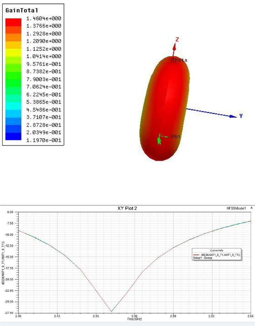
4.2 Printed Antenna
The 5005-HBS supports on-board PCB printed antenna. When the Operating Frequency is between
2.4G~2.5GH, S11 of antenna port is less than-10dB and peak gain is about 2.2dBi.
Antenna radiation pattern simulation
Antenna port S11 simulation curve
When integrating the Wi-Fi module with on board PCB printed antenna, make sure the three points as
below:
1. The area under the antenna end of the module should be keep clear of metallic components,
connectors, vias, traces and other materials that can interfere with the radio signal.
2. The area around the antenna end the module protrudes at least 10mm from the mother board PCB
and any metal enclosure.
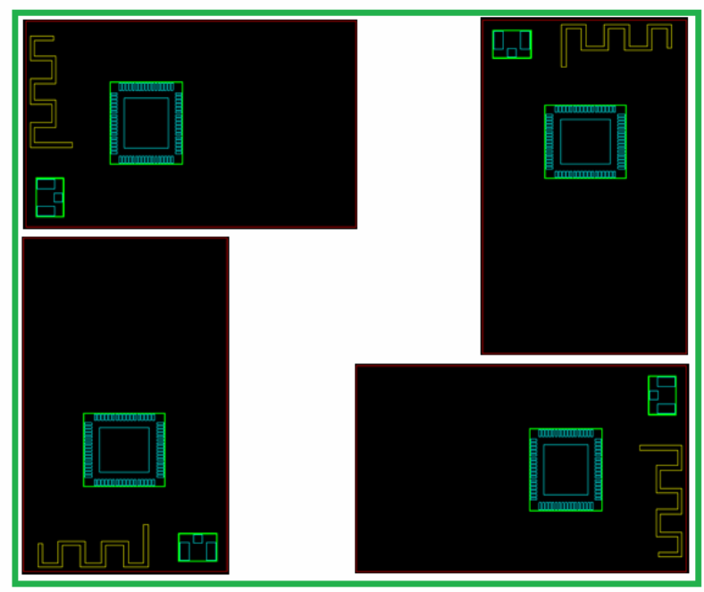
3. When planning PCB layout, it is recommended that user places the antenna of Wi-Fi module as close
as possible to the edge of boarder to ensure the good performance of antenna, which is shown in the
picture below
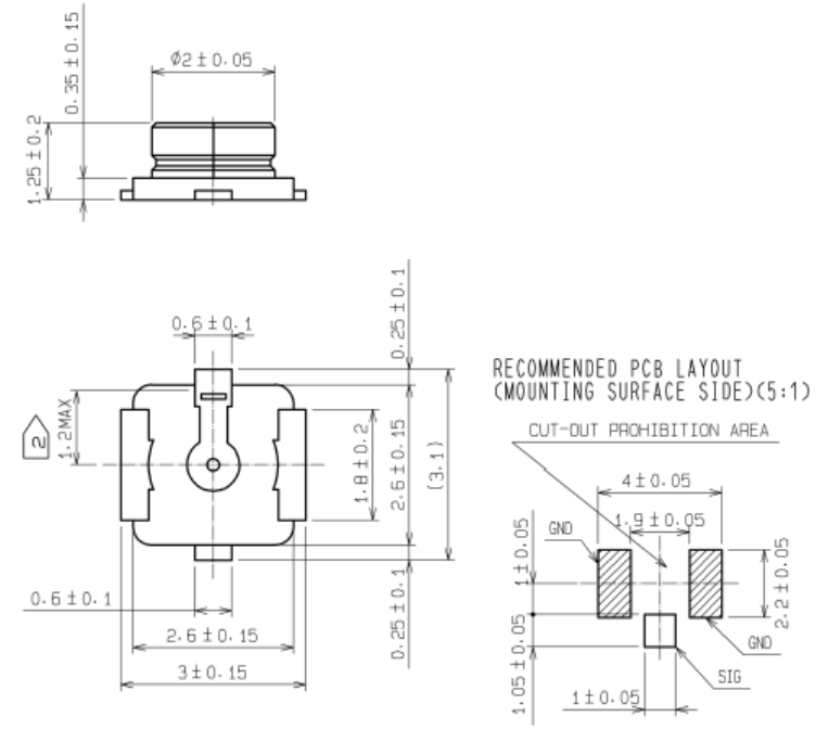
4.3 IPEX Connectors
The external antenna is also supported by this wifi module, the dimension of IPEX connector
shown as below.
5 Reference Design
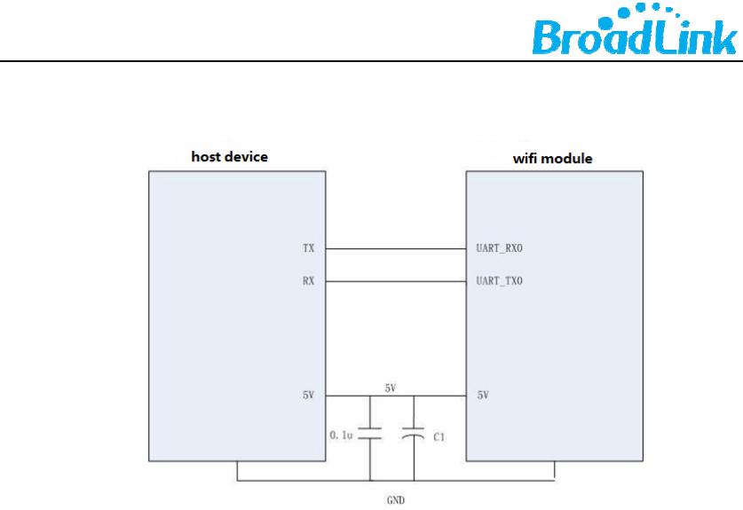
5.1 Power Supply
1. For the devices using power source of 5V, the UARTs of host device and Wi-Fi module can be
connected directly as the picture above to start communicating.
2. If the 5V power is supplied by LDO, the recommended capacitance C1 could be 10uF-22uF, if
the 5V power is supplied by DCDC, the recommended capacitance C1 could be at least 100uF
for electrolytic capacitor
3. When the wifi module is working, the peak current could reach more than 350mA, the
suggested current supply should be more than 400mA.
a. ItisaOEM/IntegratorsInstallationManual;
b. ThemoduleislimitedtoOEMinstallationONLY;
c. TheOEMintegratorsisresponsibleforensuringthattheend‐userhasnomanual
instructiontoremoveorinstallmodule;
d. Themoduleislimitedtoinstallationinmobileorfixedapplication;
e. Theseparateapprovalisrequiredforallotheroperatingconfigurations;
6 Warning
6.1 Federal Communication Commission Interference Statement
ThisequipmenthasbeentestedandfoundtocomplywiththelimitsforaClassB
digitaldevice,pursuanttoPart15oftheFCCRules.Theselimitsaredesignedto
providereasonableprotectionagainstharmfulinterferenceinaresidential
installation.Thisequipmentgenerates,usesandcanradiateradiofrequencyenergy

and,ifnotinstalledandusedinaccordancewiththeinstructions,maycauseharmful
interferencetoradiocommunications.However,thereisnoguaranteethat
interferencewillnotoccurinaparticularinstallation.Ifthisequipmentdoes
causeharmfulinterferencetoradioortelevisionreception,whichcanbedetermined
byturningtheequipmentoffandon,theuserisencouragedtotrytocorrectthe
interferencebyoneofthefollowingmeasures:
‐Reorientorrelocatethereceivingantenna.
‐Increasetheseparationbetweentheequipmentandreceiver.
‐Connecttheequipmentintoanoutletonacircuitdifferentfromthat
towhichthereceiverisconnected.
‐ Consultthedealeroranexperiencedradio/TVtechnicianforhelp.
ThisdevicecomplieswithPart15oftheFCCRules.Operationissubjecttothe
followingtwoconditions:(1)Thisdevicemaynotcauseharmfulinterference,and(2)
thisdevicemustacceptanyinterferencereceived,includinginterferencethatmay
causeundesiredoperation.
FCC Caution:Anychangesormodificationsnotexpresslyapprovedbytheparty
responsibleforcompliancecouldvoidtheuser'sauthoritytooperatethis
equipment.
IMPORTANT NOTE:
FCCRadiationExposureStatement:
ThisequipmentcomplieswithFCCradiationexposurelimitssetforthforan
uncontrolledenvironment.Thisequipmentshouldbeinstalledandoperatedwith
minimumdistance20cmbetweentheradiator&yourbody.
IEEE802.11bor802.11goperationofthisproductintheU.S.A.isfirmware‐limitedto
channels1through13.
Thisdeviceanditsantenna(s)mustnotbeco‐locatedwithanyothertransmitters
exceptinaccordancewithFCCmulti‐transmitterproductprocedures.
Referingtothemulti‐transmitterpolicy,multiple‐transmitter(s)andmodule(s)canbe
operatedsimultaneouslywithoutC2PC.
ThismoduleisintendedforOEMintegrator.TheOEMintegratorisresponsiblefor
thecompliancetoalltherulesthatapplytotheproductintowhichthiscertifiedRF
moduleisintegrated.Additionaltestingandcertificationmaybenecessarywhen
multiplemodulesareused.
USERS MANUAL OF THE END PRODUCT:
Intheusersmanualoftheendproduct,theenduserhastobeinformedtokeepat
least20cmseparationwiththeantennawhilethisendproductisinstalledand

operated.TheenduserhastobeinformedthattheFCCradio‐frequencyexposure
guidelinesforanuncontrolledenvironmentcanbesatisfied.Theenduserhastoalso
beinformedthatanychangesormodificationsnotexpresslyapprovedbythe
manufacturercouldvoidtheuser'sauthoritytooperatethisequipment.
Ifthesizeoftheendproductissmallerthan8x10cm,thenadditionalFCCpart15.19
statementisrequiredtobeavailableintheusersmanual:Thisdevicecomplieswith
Part15ofFCCrules.Operationissubjecttothefollowingtwoconditions:(1)this
devicemaynotcauseharmfulinterferenceand(2)thisdevicemustacceptany
interferencereceived,includinginterferencethatmaycauseundesiredoperation.
LABEL OF THE END PRODUCT:
Thefinalendproductmustbelabeledinavisibleareawiththefollowing"Contains
TXFCCID:2AHH3‐5005HBS".Ifthesizeoftheendproductislargerthan8x10cm,
thenthefollowingFCCpart15.19statementhastoalsobeavailableonthelabel:
ThisdevicecomplieswithPart15ofFCCrules.Operationissubjecttothefollowing
twoconditions:(1)thisdevicemaynotcauseharmfulinterferenceand(2)thisdevice
mustacceptanyinterferencereceived,includinginterferencethat
maycauseundesiredoperation.
Contact Us
Hangzhou Gubei Electronics Technology Co., Ltd.
Room 106, Building 1, No. 611 Jianghong Road, Binjiang, Hangzhou, Zhejiang, P.R.China
E Mail: henry.wen@broadlink.com.cn