Contents
- 1. User Manual Partl 1
- 2. User Manual 2
User Manual 2
26 TASCAM Model 24
5 – Basic recording
Selecting the input source
This unit has 22 inputs (22 line/16 mic inputs) with separate MIC and
standard jacks.
The LINE/INST (BAL) input jacks on channels 1–2 support high imped-
ance input, including direct guitar input.
Turn the INST switch on when connecting an electric guitar or similar
instrument directly.
ATTENTION
Do not connect to both the MIC jack and the standard input jack
(LINE/INST (BAL), LINE (BAL), L/MONO (BAL) or R (BAL)) on a
channel at the same time.
TIP
Set the INST switch to off when connecting an electric-acoustic gui-
tar with a built-in preamp or an active electric guitar, as well as when
an effect is connected between an electric guitar and this unit.
Setting the MODE switch
Using the MODE switch settings of each channel to select their input
sources individually.
LIVE: Use the signal from the input jack as the input source.
PC: Use a signal from a computer connected to the USB port as
the input source.
MTR: Use a playback signal from the SD card as an input source.
When a MODE switch is set to MTR, the signal from the input jack on
that channel will be recorded.
This function is useful when recording and playing back repeatedly
because the monitored sound is automatically switched according to
the recording or playback status.
Sounds on channels when in MTR mode
Transport status REC button off REC button on
Stop Muted Sound from input jack
Playing back Playback sound only Playback sound only +
sound from input jack
Recording Playback sound only Sound from input jack
Setting phantom power
When connecting a condenser mic that requires phantom power, press
the PHANTOM +48V switch when the recorder is stopped to turn
phantom power on/off.
N phantom power is on, the PHANTOM +48V indicator lights, and
phantom power is supplied to the MIC input jacks (1-12, 13/14-19/20).
ATTENTION
i Before connecting condenser mics, turn this unit and all equipment
to be connected off (standby).
i The PHANTOM +48V switch turns it on/off for the input channels
(1-12, 13/14-19/20) simultaneously. Do not turn the PHANTOM
+48V switch on when connecting a mic that does not require phan-
tom power.
i Do not connect or disconnect mics when the PHANTOM +48V
switch is on. Doing so could cause a loud noise and might damage
this unit and connected equipment.
i Set the following knobs and faders to their minimum values before
changing the PHANTOM +48V switch on/off setting. Depending on
the connected mics, sudden loud noises from monitoring equipment
could occur, and this could damage the equipment or harm hearing.
• GAIN knobs
• Channel faders
• SUB fader
• MON 1/MON 2 faders
• MAIN fader
• CONTROL ROOM knob
• PHONES knob
i Turn the PHANTOM +48V switch on only when using a condenser
microphone that requires phantom power. Turning the PHAN-
TOM +48V switch on when a dynamic mic or other mic that does
not require it is connected could damage this unit and connected
equipment.
i When using condenser mics that require phantom power and
dynamic mics together, be sure to use balanced dynamic mics.
Unbalanced dynamic mics cannot be used when phantom power is
enabled.
i Supplying phantom power to some ribbon mics could break them. If
you are unsure, do not supply phantom power to a ribbon mic.
TASCAM Model 24 27
5 – Basic recording
Monitoring
Monitoring is important when recording and mastering.
With this unit, monitoring is possible using an external monitoring sys-
tem (powered monitor speakers or an amp and speakers) or using stereo
headphones.
Use the CONTROL ROOM and PHONES knobs to adjust the level of
the monitoring system.
SIG indicators and level meters
The channel 1-12, 13/14-19/20 SIG indicators and level meters shown
on the Meter Screen can be used to check the levels of this unit's audio
signals.
The level meters are for visually checking signal levels and can also be
used to check whether or not signals are being input to this unit. For
example, even when you cannot hear anything monitoring,
if the Meter Screen level meters are moving, signals are being input to
this unit.
The SIG indicators light green when signals (of at least −32 dB) are input
through their channels.
If a SIG indicator lights red, the input source signal is too loud or the
GAIN knob is turned up too far.
If the SIG indicator lights red even when the GAIN knob is turned all
the way to the left, the input source signal is to loud. Lower its volume.
Track level meters (1-12, 13/14-21/22)
The show track playback signal or truck input signal levels.
Channels for which the MODE switch is set to MTR will show the fol-
lowing signal levels according to the operation status.
REC button Transport status Level meter display
Unlit PLAY Track playback signal
Blinking
(recording
standby)
PLAY
Playback signal
(automatic monitoring on)
Track input + playback
signal
(automatic monitoring off)
Stop Track input signal
Blinking
(recording) Record Track input signal
NOTE
When the playback signal is shown, the level of the recorded signal
on the track is being shown, so the levels of the level meters cannot
be changed.
When the input signal is shown, adjusting channel 1-12, 13/14-19/20
GAIN knobs will change the levels of the level meters.
MAIN MIX L/R level meters (MAIN)
These show the MAIN MIX L/R bus levels.
Recording
This unit can simultaneously record up to 24 tracks, including 22 channel
inputs and the MAIN MIX L/R bus.
The following recording operations assume that mics, guitars and other
things to record have been connected to the unit, input signals have
been assigned as track recording sources, monitoring equipment has
been connected and a song has been loaded.
1. Press the REC buttons for tracks to record.
Press the RECORD button to start recording standby. It will blink
red.
When a MODE switch is set to MTR, the signal from the input jack
on that channel will be recorded.(see “Setting the MODE switch” on
page 26)
NOTE
i The MAIN MIX L/R bus does not have a REC button, but it is always
in recording standby. The signals of the MAIN MIX L/R bus will always
be recorded if the record button is pressed.
i When the REC buttons of tracks that already have recordings is
blinking, press them to make them unlit.
2. Set the recording levels.
Use the GAIN knobs of each channel to adjust their input levels.
Watch the SIG indicators above and to the right of the GAIN
knobs, and set the levels suitably.
At the same time, check that the sound heard through headphones
or a monitoring system is not distorted and that an unintended
effect has not been set.
NOTE
If an input is too loud, the SIG indicator will light red.
If the SIG indicator lights red even when its GAIN knob is turned all
the way to the left, lower the volume of the input source.
3. Press the 0 button.
Recording will start and the 0 and 7/9 buttons will light.
The REC buttons for tracks to record will stop blinking and stay lit.
4. When recording has completed, press the 8 button.
5. Use the m/, buttons and 8 button, for example to locate to
a position you want to check.
TIP
For details about the locate function, see “Locate functionpage 30.
6. Press the 7/9 button to play the recorded tracks.
Use the channel and MAIN faders to adjust the playback levels.
Use the volume of the monitoring system to adjust the final moni-
toring level.
Use the PAN knobs of each channel to set the position of each
track signal between left and right speakers.
NOTE
i The channel PAN knobs and channel faders control the playback
output signals of already recorded tracks or the monitoring volume
of input signals. They do not control signals to be recorded.
i If you are not satisfied with a recording, repeat the above procedure
from the beginning.
28 TASCAM Model 24
5 – Basic recording
Undoing operations
If you make a mistake operating the unit or want to do a recording
over, for example,the operation last conducted can be undone. Editing,
recording and other operations can be undone.
The following types of operations can be undone.
0Recording operations
0Auto punch in/out operations
0Track clearing operations
If a song is loaded or the unit is turned off, Information used for undoing
and redoing will be lost, so undoing and redoing previous operations
will no longer be possible.
NOTE
Files used for undoing are saved on the SD card. If you want to delete
those files to make more space on the ST card, reload the current
song on the SONG Screen.
Undoing the previous operation
1. When the Home Screen is open, press the F3 button.
The following confirmation pop-up message will appear.
2. Press the F4 button to return to the state before the previ-
ous operation.
NOTE
To cancel undoing, press the F1 button.
Redoing an undone operation
1. After undoing, when the REDO button appears on the Home
Screen, press the F3 button.
The following confirmation pop-up message will appear.
2. Press the F4 button to restore the previous operation and
return to the state before undoing.
NOTE
To cancel undoing, press the F1 button.
Using the built-in effects
This unit has built in effects, so you can apply effects without an external
effect device.
Channels 1-12 and 13/14-19/20 can have an effect applied. Their signals
are sent to the built-in effect by the FX bus.
The return signal is returned to the MAIN MIX L/R and MONITOR OUT 1/2
buses.
1. Use the FX knobs of each channel to adjust the levels of signals
sent to the FX bus.
2. Use the EFFECT Screen to select the type of effect.(see “Setting the
built-in effect” on page 28)
3. Use the TO MAIN LR and TO MON 1/TO MON 2 knobs to adjust
the return levels for the MAIN MIX L/R and MONITOR OUT 1/2
buses.
4. When the AFL switch is on, use the CONTROL ROOM/PHONES
knob to adjust the return level.
NOTE
The sound with the effect applied can be monitored from the CON-
TROL ROOM L/R jacks or PHONES jack.
Setting the built-in effect
1. Press the SELECT button to open the EFFECT Screen.
2. Select TYPE, and press the MULTI JOG dial to open the effect type
list pop-up.
Set the built in effect type.
Options: 1.SMALL HALL (default), 2.LARGE HALL,
3.SMALL ROOM, 4.LARGE ROOM, 5.PLATE,
6.STUDIO, 7.LIVE, 8.SHORT DELAY, 9.DELAY,
10.PING PONG, 11.CHORUS, 12.FLANGER,
13.DELAY+SHALL, 14.DELAY+LHALL,
15.CHORUS+SHALL, 16.CHORUS+LHALL
TASCAM Model 24 29
5 – Basic recording
3. Select PARAMETER, and adjust the amount of the set effect.
Options: 1 (default), 100
NOTE
Press the F4 button to set the CURRENT STATUS, TYPE and
PARAMETER items to their default values.
4. Press the F3 button to turn the built-in effect on.
The CURRENT STATUS will change from OFF to ON.
NOTE
Press the F2 button to turn the built-in effect off.
5. Press the F1 button to return to the Home Screen.
30 TASCAM Model 24
6 – Recorder functions
Locate function
When the Home Screen is open, you can use the MULTI JOG dial to set
the locate point.
On the Home Screen, the current position of the recorder is shown as a
time in hours (h), minutes (m) and seconds (s).
By setting the time in this display area, you can change the current posi-
tion of the recorder.
Changing the playback position
When the Home Screen is open and the recorder is stopped or playing
back, you can use the MULTI JOG dial to set the locate point.
Using the direct locate function to locate
1. When the Home Screen is open and the recorder is stopped, press
the MULTI JOG dial to enable direct locate mode. A cursor will
appear at the location to be changed in the recorder counter.
2. Turn the MULTI JOG dial to change a value, and press the MULTI
JOG dial to confirm it and move the cursor to the next item.
3. Change the seconds, minutes and hours in that order to move to
that time as the current recorder position.
4. Press the 7/9 button to start playback or the 0 button to start
recording from that position.
Repeat playback function
The repeat playback function can be used to play something over and
over.
When the Home Screen is open, press the F2 button to set the
repeat playback function.
Nothing shown: the current song will keep playing.
: The current song will play and then stop.
: The current song will play repeatedly.
Punch in/out function
Punching in and out is a technique used to replace parts of already
recorded tracks.
You can start playback of recording, switch to recording when it reaches
the part to be replaced (punch in), and then switch back to playback (or
stop) when the end of that part is reached (punch out).
1. Determine the part you want to replace in advance.
Select a point where the replacement audio can be combined well
with the original track audio.
2. Press the REC button for the track with the part to be replaced to
enter recording standby (REC button blinks).
NOTE
Punch in recording is not possible when the REC button is on for
eight or more channels.
3. Start playback before the part to be replaced.
4. When the part to be replaced is reached, press the 0 button, and
perform the part.
Recording will start (punch in).
5. When the end of the part to be replaced is reached, press the 8
button.
Recording will stop.
Using the footswitch to punch in/out
By connecting a commercially-available footswitch to the
FOOTSWITCH jack (TS standard) on the top of the unit, you can use it
to punch in/out.
To use a footswitch to punch in/out, you must set the foot switch
function assignment to PUNCH IN/OUT in advance.(see “Setting up the
footswitch” on page 31)
At step 4 above, press the footswitch instead of the 0 button, and at
step 5 press it again instead of the 8 button.
TASCAM Model 24 31
6 – Recorder functions
Setting up the footswitch
Use the FOOTSW Screen to set the footswitch.
1. Open the FOOTSW Screen when the recorder is stopped.(see “Menu
operation procedures” on page 18)
2. Turn the MULTI JOG dial to select the function to assign to the
footswitch.
Option Meaning
PLAY / PAUSE
(default)
Press to start playback when paused. Press to
stop when in any other state.
PUNCH IN / OUT Press during playback to punch in. Press when
recording to punch out.
FX MUTE Mute the built-in effect signal.
3. Press the MULTI JOG dial to confirm the assigned
function.
A * appears next to the selected function.
4. Press the F1 button to return to the MENU Screen.
Setting the footswitch polarity
The setting of this unit can be changed according to the polarity of the
footswitch being used.
Select NORMALLY OPEN or NORMALLY CLOSED so that the actual footswitch
movement matches that shown by the illustration on the screen.
1. Open the FOOTSW Screen when the recorder is stopped.(see “Menu
operation procedures” on page 18)
2. Press the F4 button to open the POLARITY Screen, and turn
the MULTI JOG dial to set the footswitch polarity.
Options: NORMALLY OPEN (default), NORMALLY CLOSED
3. Press the F1 button to return to the FOOTSW Screen.
Automatic punch in/out function
Using the automatic punch in/out function, you can automatically
record between punch in and out points set in advance.
To use automatic punch in/out recording, start playback from a pre-roll
point before the punch in point where recording will start.
Recording will stop when the punch out point is reached, but playback
will continue for two seconds before stopping.
Setting the punch in/out points
1. Open the AUTO PUNCH Screen when the recorder is stopped.(see
“Menu operation procedures” on page 18)
2. Press the 7/9 button to start playback.
3. Press the MULTI JOG dial to set the punch in and out points.
The set points are shown next to the IN and OUT items.
NOTE
i Press the F2 button to clear set punch in and out points.
i Press the F3 button to select either the punch in or out point.
An * will appear next to the selected item.
4. Press the 8 button to stop playback.
5. Press the F4 button to turn the automatic punch in/out
function on.
The icon appears on the AUTO PUNCH Screen.
6. Press the F1 button to return to the MENU Screen.
TIP
i By setting only the punch in point, you can start recording with auto-
matic punch in and then continue recording until you press the 8
button to stop.
i By setting only the punch out point, you can start recording by press-
ing the 0 button and then stop recording with automatic punch
out.
32 TASCAM Model 24
6 – Recorder functions
Setting a pre roll point
When using automatic punch in, the amount of playback time before
the punch in point can be set (pre roll point).
1. Select A.PUNCH PRE ROLL on the MENU screen to open the A.PUNCH
PRE ROLL screen.(see “Menu operation procedures” on page 18)
2. Set the pre-roll point.
Option Meaning
OFF Do not locate to a point before the punch in
point.
1sec. – 10sec.
(default: 2sec.)
Locate to a pre roll point the set time before
the punch in point and start playback.
3. Press the F1 button to return to the MENU Screen.
Rehearsing punching in and out
You can rehearse before punch in/out recording. In rehearsal, recording
will not occur, but monitoring will be the same as if recording.
1. Press the MENU button when the recorder is stopped to open the
Home Screen.
Confirm that the icon appears on the Home Screen.
2. Press the REC buttons for the tracks you want to record using
automatic punch in/out.
NOTE
Punch in recording is not possible when the REC button is on for
eight or more channels.
3. Press the 7/9 button.
Auto punch in/out rehearsal starts.
oThe transport starts playback from the pre-roll point. Both
track playback and input source signals can be monitored.(see
“Setting a pre roll point” on page 32)
oWhen the punch in point is reached, only the input source sig-
nal will be monitored. The 0 button will blink showing that it
is rehearsal mode.
oWhen the punch out point is reached, both track playback
and input source signals will be monitored. The 0 button will
become unlit.
oPlayback will automatically stop two seconds after the punch
out point. The 7/9 button will blink.
Rehearsal can be repeated.
Using automatic punching in and out
Follow these procedures to punch in and out automatically and record.
1. Confirm that the icon appears on the Home Screen.
2. Press the REC buttons for the tracks you want to record using
automatic punch in/out.
NOTE
Punch in recording is not possible when the REC button is on for
eight or more channels.
3. Press the 0 button.
oThe transport starts playback from the pre-roll point. Both
track playback and input source signals can be monitored.(see
“Setting a pre roll point” on page 32)
oWhen the punch in point is reached, only the input source sig-
nal will be monitored. The 0 button will light.
oWhen the punch out point is reached, both track playback
and input source signals will be monitored. The 0 button will
become unlit.
oPlayback will automatically stop two seconds after the punch
out point. The 7/9 button will blink.
TASCAM Model 24 33
7 – Track editing
Clearing tracks
The selected track will be cleared.
1. Open the TRACK CLEAR Screen when the recorder is stopped.(see
“Menu operation procedures” on page 18)
2. Turn the MULTI JOG dial to select the track to clear, and press the
MULTI JOG dial.
A confirmation message will appear.
NOTE
Press the F2 button to open a message confirming that you
want to clear all tracks.
3. Press the F4 button to clear the track(s).
NOTE
i To cancel clearing tracks, press the F1 button.
i Undoing is possible only for the last cleared track.
4. After clearing tracks completes, the TRACK CLEAR Screen will
reopen.
Importing tracks
You can import audio files that you have to tracks in the current song.
Files that can be imported to tracks must be WAV format (“.WAV”
extension).
To import an audio file with a different format (.mp3, etc.) to this unit, it
must be converted to a WAV file that matches the format of the song it
will be imported into beforehand.
1. Connect this unit with a computer.(see “Connecting with a Com-
puter” on page 37)
2. Use the computer to copy WAV files on it to this unit's MUSIC folder.
3. Follow the proper disconnection procedures on the computer
before disconnecting the USB cable.(see “Disconnecting” on page
37)
4. Open the TRACK IMPORT Screen when the recorder is stopped.(see
“Menu operation procedures” on page 18)
WAV files in the MUSIC folder will be shown.
5. Select a WAV file to import.
oTurn the MULTI JOG dial to select a WAV file.
oPress the MULTI JOG dial when a folder is selected to show
its contents.
oPress the F1 button to return to the MENU Screen.
oPress the F2 button to move up one level.
6. Press the F4 button.
On the TRACK IMPORT Screen, the name of the file to be imported
and the TARGET TRACK(S) item are shown.
NOTE
i To cancel importing a track, press the F1 button.
i Importing is not possible under the following conditions.
• Not enough open space is available
• There are no empty tracks
• The characteristics of the WAV file you are trying to import differ
from the current song.
Example: Trying to import a 48kHz WAV file when the current
song is 44.1kHz
i If there is no file that can be imported, a No File pop-up message
will appear.
i If the imported WAV file is stereo, selection will be of two consecutive
tracks.
7. Select the track to import, and press the F4 button to import
it.
8. When importing completes, the TRACK IMPORT Screen reopens.
34 TASCAM Model 24
8 – Settings and Information
Viewing information
Use the INFORMATION screen to view various types of information about
the unit. Follow the procedures below to view the INFORMATION screen.
1. On the SYSTEM Screen, select INFORMATION to open the Information
Screen.(see “Menu operation procedures” on page 18)
The Information Screen has 3 pages. The CARD page opens first.
2. Turn the MULTI JOG dial to cycle through the CARD, SONG and
FIRMWARE screens.
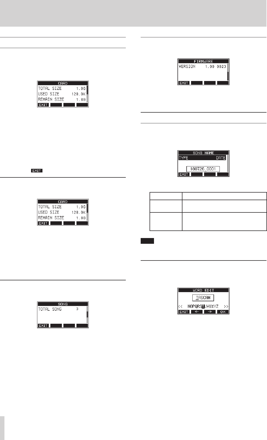
CARD Screen
Shows the use status of the currently loaded SD card
SONG Screen
Shows the number of songs on the loaded SD card
FIRMWARE Screen
Shows the unit’s system firmware version.
3. Press the F1 button to return to the MENU Screen.
CARD Screen
The CARD Screen shows the status of the currently loaded SD card.
TOTAL SIZE
Shows the total amount of space on the SD card.
USED SIZE
Shows the amount of space used on the SD card.
REMAIN SIZE
Shows the amount of space unused on the SD card.
SONG Screen
The SONG Screen shows the use status of the MTR folder.
TOTAL SONG
This shows the total number of songs in the MTR folder.
FIRMWARE Screen
The FIRMWARE Screen shows the firmware version.
VERSION
This shows the system firmware version of this unit.
Setting the song name format
Set the name format is used by the unit for creative songs.
1. On the SYSTEM Screen, select SONG NAME to open the SONG NAME
Screen.(see “Menu operation procedures” on page 18)
2. Set the file name format.
Option Meaning
DATE (default) Use the date for the song name.
(Example: 180101_0001)
WORD
Use the 6-character song name set on the
EDIT screen.
(Example: TASCAM_0001)
NOTE
The date is set using the unit’s internal clock. (see “Setting the built-in
clock date and time” on page 22)
Setting the WORD item
To set the characters, select WORD on the TYPE Screen. An EDIT item will
appear on the SONG NAME Screen that can open the WORD EDIT Screen.
For details about how to set characters, see “Editing textpage 25.
TASCAM Model 24 35
8 – Settings and Information
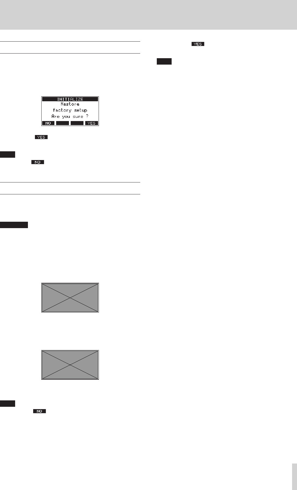
Restoring factory default settings
You can restore the various settings stored in the memory of the unit to
their factory default values.
Use the following menu procedures to do so.
1. On the SYSTEM Screen, select INITIALIZE to open the INITIALIZE
Screen.(see “Menu operation procedures” on page 18)
2. Press the F4 button to restore the factory default settings.
3. When the setting completes, the SYSTEM Screen will reopen.
NOTE
i Press the F1 button to cancel execution.
i The date and time setting is not initialized.
Formatting SD cards
Formatting erases all music files on the SD card and automatically cre-
ates new “MTR”, “ MUSIC” and “UTILITY” folders as well as a “tascam_
m.sys” file.
ATTENTION
i Formatting an SD card erases all the data on it. This cannot be
undone.
i Always use this unit to format media to be used with it. Operation of
this unit might be affected when using an SD card that has been for-
matted by a computer or other device.
1. On the SYSTEM Screen, select MEDIA FORMAT to open the MEDIA
FORMAT Screen.(see “Menu operation procedures” on page 18)
QUICK: Execute quick formatting.
ERASE: Erase and format the card.
2. Select the format method, and press the MULTI JOG dial.
A confirmation message will appear on the QUICK or ERASE Screen.
Shown when QUICK selected
NOTE
Press the F1 button to cancel formatting and return to the
previous screen.
3. Press the F4 button to start formatting.
4. When formatting is complete, the SYSTEM Screen will reopen.
NOTE
The writing speeds to SD cards and other storage media that use
flash memory tend to decrease after writing occurs repeatedly.
If the writing speed decreases, this could have a negative impact on
recording.
Using the ERASE function of this unit should restore the writing speed
of the SD card.*
For this reason, we recommend using the ERASE function at the fol-
lowing times.
oWhenever the card has been written to until it became com-
pletely full
oOn a regular schedule (about once per month)
oBefore starting important recordings
*Writing speed might not be restored depending on the SD card con-
dition (including malfunction and age).
36 TASCAM Model 24
8 – Settings and Information
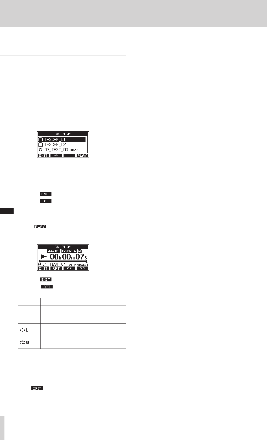
Playing WAV files on SD cards
(SD PLAY mode)
The WAV files in the MUSIC folder on an SD card can be played back.(see
“Loading WAV files from a computer” on page 38)
The following audio file formats can be played back in SD PLAY mode.
WAV: 44.1/48kHz, 16/24-bit
BWF: 44.1/48kHz, 16/24-bit
Playback signal is sent from channels 21 and 22.
1. Set the channel 21/22 MODE switch to MTR.
2. Set the channel 21/22 MON 1/MON 2 and BAL knobs and the
channel fader to their middle positions
3. Open the SD PLAY Screen when the recorder is stopped.(see “Menu
operation procedures” on page 18)
4. Select a file to play back
oTurn the MULTI JOG dial to select a WAV file.
oPress the MULTI JOG dial when a folder is selected to show
its contents.
oPress the F1 button to return to the MENU Screen.
oPress the F2 button to move up one level.
NOTE
Only WAV files can be played back. MP3 files will not be shown.
5. Press the F4 button or 7/9 button to start WAV file
playback.
The SD PLAY Screen will show playback status.
oPress the F1 button to return to the SD PLAY Screen.
oPress the F2 button to turn the repeat playback func-
tion on and select the repeat playback mode.
Display Meaning
No
indicator
The folder that contains the currently playing
WAV file will play back, and then playback will
stop.
The currently playing WAV file will play back
repeatedly.
The folder that contains the currently playing
WAV file will play back repeatedly.
oPress the F3 (<<) button to skip to the beginning of the WAV
file. Press near the beginning of the WAV file to skip to the
beginning of the track before it.
oPress the F4 (>>) button to skip to the beginning of the next
WAV file.
6. Press the F1 button twice to return to the MENU Screen.
TASCAM Model 24 37
9 –Using a computer to transfer data
By connecting this unit with a computer using a commercially-available
USB cable, you can back up song data on the SD card in the unit to the
computer, as well restore backed up song data to the unit. You can also
export track and stereo master files from songs to the computer and
import audio files from the computer.
Backed up data can be restored to other Model 24/Model 20 units.
Since this allows you to freely move files between Model 24/Model 20
units, you can easily conduct additional recording or mixing at different
locations.
ATTENTION
Always turn the unit's power off (standby) before removing the SD
card. You can conduct the same operations by removing the SD
card from the unit and connecting it directly to a computer or by
using a card reader instead of using USB to connect the unit and the
computer.
This unit can transfer the following data to a computer.
Entire songs
This unit can transfer all the data for a song from the MTR folder to a
computer. This operation is called "backing up". Data backed up to a
computer can also be transferred to the MTR folder, and restored as a
song file. This operation is called "restoring".
ATTENTION
Do not change names, delete or otherwise alter individual files inside
the MTR folder. Doing so could prevent loading data as a song and
make proper recording and playback operations impossible.
WAV files
By placing WAV files from the computer into the MUSIC folder, you can
import them to song tracks. Moreover, WAV files in the MUSIC folder can
be played back in SD PLAY mode.
Connecting with a Computer
You cannot use this unit’s recording, playback and other recorder func-
tions when it is connected to a computer by USB.
To connect with a computer, use a Type-A to Type-B USB2.0 cable to
connect the USB port on the back of this unit to a USB port on the
computer.
The USB cable can be connected either before or after turning this unit
on.
1. Use a USB cable (Type-A to Type-B) to connect the computer to this
unit's USB port.
ATTENTION
The unit should be connected directly with the computer instead of
via a USB hub.
2. On the MENU Screen, select STORAGE to open the STORAGE Screen.(see
“Menu operation procedures” on page 18)
3. To connect with the computer, press the F4 button.
The unit enters USB storage mode and connects with the computer.
Make sure that the SD card is inserted properly.
4. This unit appears on the computer as an external drive named
“TASCAM_M” (if the card was formatted by this unit).
Click the “TASCAM_M” drive on the computer to show the “MTR”,
“MUSIC” and “UTILITY” folders.
ATTENTION
i This unit receives power through its power cord. It cannot be pow-
ered by USB.
i Do not disconnect the power cord or turn off the power during data
transfer. Data will be lost if the power is interrupted during transfer.
Lost data cannot be restored.
i Do not change the names of folders in “TASCAM_M”.
NOTE
i Do not change names, delete or otherwise alter individual files inside
the MTR folder.
i The UTILITY folder is used when updating the unit system, for
example.
5. Press the F1 button to return to the Meter Screen.
Disconnecting
Before disconnecting the USB cable, use the proper procedures for your
computer to unmount the unit (as an external drive).
See the computer’s operation manual for instructions about how to
unmount an external volume.
Press the F1 button to disconnect from the computer and return
to the Home Screen.

38 TASCAM Model 24
9 –Using a computer to transfer data
Loading WAV files from a computer
1. Use a USB cable (Type-A to Type-B) to connect the computer to this
unit's USB port.(see “Connecting with a Computer” on page 37)
2. Click the “Model 24” drive on the computer to show the “MTR”,
“MUSIC” and “UTILITY” folders.
3. Drag and drop files on the computer that you want to transfer to
the unit to the MUSIC folder.
ATTENTION
i The “UTILITY” folder is used when updating the unit system, for
example.
i Do not change names, delete or otherwise alter individual files inside
the “MTR” folder. Doing so could prevent loading data as a song and
make proper recording and playback operations impossible.
TIP
i You can manage the content of “MTR” or “MUSIC” folders from the
computer.
i You can create subfolders in the "MUSIC" folder up to the second
level for use with this unit. The DR-44WL cannot recognize sub-fold-
ers and files located at the third layer level or below. The unit cannot
recognize subfolders and audio files on the third level or below.

TASCAM Model 24 39
10 – USB audio interface functions
Installing the dedicated software
(Windows only)
To use this unit as a USB audio interface with a Windows computer, dedi-
cated software must be installed on the computer.
Download the latest software for the operating system you are using
from the TEAC Global Site (http://teac-global.com/).
Installing the dedicated software will install a Windows driver and a Win-
dows Settings Panel application.
ATTENTION
i Before starting to install software, quit other applications.
i With a Mac, the standard OS driver will be used, so there is no need
to install any software.
Installing the Windows dedicated software
Follow the procedures below to install the Windows dedicated software.
ATTENTION
i Complete installation of the Windows dedicated software on the
computer before connecting the unit to it with the USB cable.
i If you connected the unit to the computer using the USB cable
before installing the Windows dedicated software and the “Found
New Hardware Wizard” launched, close the Wizard and disconnect
the USB cable.
Windows dedicated software installation procedures
1. Download the latest Windows dedicated software for the operat-
ing system you are using from the TEAC Global Site (http://teac-
global.com/) and save it on the computer to be used with the unit.
2. Uncompress the saved software (zip file) on the computer desktop
or another location.
3. Double-click the “TASCAM_ModelSeries_Installer_x.xx.exe” file
in the folder that appears after uncompression to launch the instal-
lation software.
ATTENTION
If you open a zip file without decompressing it and double-click the
“TASCAM_US-2x2_4x4_Mixer_x.xx.exe” file in the folder that opens,
installation will not start. Right-click the zip file and select “Extract
All”, for example, to decompress it and then try again.
4. When a Security Warning or User Account Control screen
appears, click the “Ye s ” button.
5. Read the contents of the User License Agreement, and select “I
accept the agreement” if you agree to the terms. Then, click the
“Next (N)” button.
6. Next, click the “Install” button.
7. Next, click the “Install” button to start installation. (Windows 7 only)
8. The following screen appears when installation has completed. The
following screen appears when installation has completed.
Click the “Finish (F)” button.
The installer will quit and the Windows Settings Panel will launch.
NOTE
The first time you connect the unit by USB to the computer after
installing the software, installation of the device driver will be exe-
cuted. Some time might be necessary before the unit is recognized
because Windows Update will be automatically searched at this time.
If the unit is still not recognized after a while, open the software
installation screen from the notification area at the bottom right of
the computer display, and click “Skip obtaining driver software from
Windows Update” to stop the search.

40 TASCAM Model 24
10 – USB audio interface functions
Uninstalling the Windows dedicated software
Uninstalling from the Programs and Features Control Panel
NOTE
Normally, there is no need to uninstall the dedicated software. Follow
these procedures if a problem occurs or you no longer intend to use
the unit with the computer.
1. From the Start menu, open the Control Panel and launch Pro-
grams and Features.
NOTE
i In Windows 10, right-click the Start button and click Control Panel
when it appears.
i In Windows 8.1, click the button that appears at the bottom left of
the Start screen to open the Apps screen, and click Control Panel.
2. If “View by:” is set to “Category”, click “Uninstall a program” under
the “Program” item.
If “View by:” is set to “Large icons” or “Small icons”, click “Programs
and Features”.
3. Select “TASCAM ModelSeries x.xx” from the list, and double-click
it.
4. Then, follow the instructions that appear on the screen.
Opening the Settings Panel (Windows only)
Open the Settings Panel in the following manner.
Windows 10
0Click the Windows Start button and select All Programs w TASCAM
w Model Series Settings Panel.
Windows 8.1
0Right-click the Windows Start button and select Control Panel.
NOTE
You can also left-click the Start button to open the Start Screen. Click
the button to open the Apps screen, and select Model Series Set-
tings Panel under TASCAM.
Windows 7
0Click the Windows Start button and select All Programs w TASCAM
w Model Series Settings Panel.
Windows Settings Panel overview
1 Status display area
This shows the current status of the software.
Item displayed Meaning
Software Ver This is the software version.
Firmware Ver This is the firmware version used by the con-
nected unit.
Device
This is the name of the connected unit.
(“No Device” is shown when no device is
connected.)
Sample Rate
This shows the sampling frequency of the
current song.
If an SD card is not loaded, this shows the
sampling frequency set by the computer.
2 Buffer Size
You can adjust the size of the buffer used to handle the audio input
and output signals transferred to and from the computer.
Smaller buffer sizes result in less audio signal delay (latency), but
require high-speed processing by the computer.
If the processing cannot keep up, for example, due to other system
operations, clicking and popping noises might occur and the audio
signal might even drop out.
Increasing the buffer size will stabilize operation and suppress nega-
tive effects on audio signals, but the delay in audio signals sent to the
computer will increase.
You can use the slider on the panel to adjust the buffer size for this
unit according to the use conditions.
Options
64, 128, 256, 512 ,1024, 2048

TASCAM Model 24 41
11 – Messages
The following is a list of messages that appear in pop-up windows.
Refer to this list if one of these pop-up messages appears on the Model 24 and you want to check the meaning or determine a proper response.
Message Meaning and response
Card Error The SD card cannot be recognized properly. Replace the card.
Card Full The SD card has no remaining capacity. Erase unnecessary files or transfer them to a computer.
Dup File Name A file with the same name already exists. Change the file name.
File Not Found The file cannot be found or the file may be damaged. Check the relevant file.
No sys file
Make sys file
The system file is missing. This unit requires a system file for operation.
When this message appears, press the MULTI JOG dial to create a system file.
Song Protected This operation is not possible because the song is protected. Remove protection.
Invalid Card
Change Card Something might be wrong with the SD card. Change the SD card.
I/O Too Short The time between the punch in and out points is too short. Set them with at least 1 second between them.
MBR error
Init card
The SD card is not formatted properly or the card is broken.
Change the SD card or press the MULTI JOG button while this message is being shown to format the card. Formatting
will erase all the data on the SD card.
No Card A SD card is not set.
Insert a recordable SD card.
Non-supported The file format is not supported. Please see Playing WAV files on SD cards
(SD PLAY mode)page 36 for file formats that this unit can use.
Card Protected The SD card is write-protected. Disable SD card write-protection.
USB Fs mismatch The sampling rate of the current song and the USB audio interface are not the same.
Change the sampling rate of one so that they are the same.
Current Song The current song cannot be deleted. To delete the current song, load another song first.
Invalid I/O point
The punch in/out point settings on the AUTO PUNCH Screen are not set correctly.
Automatic punching in/out occurred at an invalid position for the punch in or out point.
Start the automatic punch operation from a valid point.
Write error
REC continue
Writing to the SD card timed out. This has caused audio to be interrupted and noise to occur.
A BOF mark is added at the point when audio was interrupted.
Card slow
Check BOF MARK
SD card writing performance has become worse.
A BOF mark has been added at the point when audio was interrupted because writing to the SD card timed out.
Check the audio around the BOF mark.
Execute the erase format function or change the SD card.
Need to set
I/O point.
A punch in/out point is not set for the automatic punch in/out function.
Set the punch in/out points.
Sample rate
Unmatch The sampling frequency of the WAV file to be imported does not match the current song.
Bit length
Unmatch The bit rate of the WAV file to be imported does not match the current song.
Remain time is
not enough
The SD card does not have enough open space, so importing is not possible.
Erase unnecessary files or transfer them to a computer.
8 track
punch in limit
The maximum number of tracks for punch in recording is eight.
Press REC buttons to reduce the number of recording tracks to eight or less.
Song is not
loaded
No song is loaded.
Create a new song or load a song.
Song number full The maximum number of songs that can be created on an SD card is 100.
Erase unnecessary songs or transfer them to a computer.
SD PLAY:
cannot record
SD PLAY mode is for playback only.
Recording is not possible.
UNDO not available UNDO is not possible in the current state.
SD CARD cluster
size error
Recording is not possible because the SD card cluster size is not right.
Back up the contents of the SD card on a computer and then format it with this unit.
Then, restore the data from the computer.
Import error.
no track
Importing is not possible because there are no open tracks.
Use TRACK CLEAR to clear a track.(see “Clearing tracks” on page 33)
Already protected The selected song is already protected.
Already unprotected The selected song is already unprotected.

42 TASCAM Model 24
11 – Messages
Message Meaning and response
Can't Save Data
If any of these errors occurs, turn the unit off and restart it.
If these error messages continue to appear frequently, please contact the store where you purchased this unit or TAS-
CAM customer support.
Device Error
File Error
Not Continued
Player Error
Writing Failed
Sys Rom Err
System Err XX
(XX is a number.)

TASCAM Model 24 43
12 – Troubleshooting
If you are having trouble with the operation of this unit, please try the following before seeking repair.
If these measures do not solve the problem, please contact the store where you purchased this unit or TASCAM customer support service.
The unit will not turn on.
0Confirm that the power plug and other connectors are inserted
completely.
The SD card is not recognized.
0Confirm that the SD card is inserted completely.
The unit is playing back but no sound is output
0Are that channel faders raised to suitable levels?
0Is the MAIN fader raised to a suitable level?
0Is a monitoring system correctly connected to the PHONES jack or
CONTROL ROOM L/R jacks?
Is the monitoring system set up correctly?
0Is the PHONES knob or CONTROL ROOM knob place to a suitable
level?
The sound I want to record is distorted
0Are the channel GAIN knobs set too high?
Are the input source levels to high?
0Is the EQ set too high?
0Are any channel faders or the MAIN fader raised too high?
0Is the monitoring level too high, causing the monitoring system to
distort?
Noise occurs when a passive guitar or bass is connected
directly
0Connecting another device to the unit's SUB OUTPUT jacks (stereo
output) could reduce noise.
0It could be affected by interference noise from another device, for
example. If a power amplifier or other device with a large trans-
former, or a fluorescent light, for example, is nearby, changing the
distance or orientation of such devices could reduce noise.
Playback is not possible.
0If you are trying to play a WAV file, confirm that it uses a sampling fre-
quency (44.1/48 kHz) and a bit depth (16-bit) that are supported by
this unit.
There is noise.
0Confirm that the connection cables do not have contact issues.
Sound breaks up or is noisy.
0Are there any wireless LAN devices, other Bluetooth devices, micro-
wave ovens or similar equipment nearby?
Keep such devices as far away as possible during use.
0Try reducing the distance between this unit and the other Bluetooth
device. Try changing the positions of this unit and the other Blue-
tooth device.
0The operation of apps other than for music playback on the smart-
phone could cause the sound to break up. In this case, stop operation
of apps other than the one used for music playback.
Cannot connect or communication is interrupted.
0Confirm that the other Bluetooth device power is on and that its
Bluetooth function is on.
0Confirm that the other Bluetooth device is not too far away.
Are there walls or other obstacles, for example, between this unit and
the other Bluetooth device?
The body of this unit itself could interrupt transmission if the other
Bluetooth device is behind it.
Try changing the positions of this unit and the other Bluetooth
device.
0Turn OFF and restart the DR-44WL.
0Remove the "Model 24" pairing record from the other Bluetooth
device, and try pairing the unit with that Bluetooth device again.
Cannot pair with another device.
0Confirm that the other Bluetooth device supports A2DP.
0Confirm that the other Bluetooth device is in a state that allows trans-
mission. For details, check the operation manual of that Bluetooth
device.
0Turn the power off for both this unit and the other Bluetooth device
once, turn them both on again and try pairing them.
0Turn off Bluetooth devices other than the one that you are trying to
pair with.
0Remove the "Model 24" pairing record from the other Bluetooth
device, and try pairing the unit with that Bluetooth device again.

44 TASCAM Model 24
13 – Specifications
General
Supported media
SD cards (512MB–2GB)
SDHC cards (4GB–32GB)
SDXC cards (64GB–128GB)
Recording file formats
WAV: 44.1/48kHz, 16/24-bit
Playback file formats
WAV, MP3
Inputs and outputs
Analog audio input and output ratings
MIC input jacks (1-12)
Connectors: XLR-3-31 (1: GND, 2: HOT, 3: COLD)
Input impedance: 3.3 kΩ
Nominal input level (GAIN knob at maximum): −66 dBu
Nominal input level (GAIN knob at minimum): +2 dBu
LINE/INST (BAL) input jacks (1-2)
Connectors: 6.3mm (1/4") standard TRS jacks (Tip: HOT, Ring: COLD,
Sleeve: GND)
Input impedance: 1 MΩ
Nominal input level (GAIN knob at maximum): −65 dBu
Nominal input level (GAIN knob at minimum): +4 dBu
LINE (BAL) input jacks (3-12)
Connectors: 6.3mm (1/4") standard TRS jacks (Tip: HOT, Ring: COLD,
Sleeve: GND)
Input impedance: 10 kΩ
Nominal input level (GAIN knob at maximum): −46 dBu
Nominal input level (GAIN knob at minimum): +2 dBu
L/MONO (BAL)/R (BAL) input jacks (13/14-19/20)
Connectors: 6.3mm (1/4") standard TRS jacks (Tip: HOT, Ring: COLD,
Sleeve: GND)
Input impedance: 10 kΩ
Nominal input level (GAIN knob at maximum): −50 dBu
Nominal input level (GAIN knob at minimum): +4 dBu
−10dBu input jacks (21/22)
Connectors: RCA pin jacks
Input impedance: 47 kΩ
Nominal input level: -10 dBV
Maximum input level: +10 dBV
STEREO input jack (21/22)
Connector: 3.5mm (1/8") stereo mini jack
Input impedance: 22 kΩ
Maximum input level: +6 dBV
MAIN OUTPUT connectors
Connectors: XLR-3-32 (1: GND, 2: HOT, 3: COLD)
Rated output level: +4 dBu
Maximum output level: 22dBu
Output impedance: 100 Ω
SUB OUTPUT connectors
Connectors: 6.3mm (1/4") standard TRS jacks (Tip: HOT, Ring: COLD,
Sleeve: GND)
Rated output level: +4 dBu (1.228 Vrms)
Maximum output level: +24 dBu (12.277 Vrms)
Output impedance: 100 Ω
MON 1/MON 2 AUX OUTPUT jacks
Connectors: 6.3mm (1/4") standard TRS jacks (Tip: HOT, Ring: COLD,
Sleeve: GND)
Rated output level: +4 dBu (1.228 Vrms)
Maximum output level: +22 dBu (9.757 Vrms)
Output impedance: 100 Ω
FX AUX OUTPUT jack
Connector: 6.3mm (1/4") standard TS jacks (Tip: HOT, Sleeve: GND)
Rated output level: +4 dBu (1.228 Vrms)
Maximum output level: +22 dBu (9.757 Vrms)
Output impedance: 100 Ω
CONTROL ROOM jacks
Connectors: 6.3mm (1/4") standard TRS jacks (Tip: HOT, Ring: COLD,
Sleeve: GND)
Rated output level: +4 dBu (1.228 Vrms)
Maximum output level: +22 dBu (9.757 Vrms)
Output impedance: 100 Ω
Phones jack
Connector: 6.3mm (1/4") standard stereo jack
Maximum output: 100mW + 100mW (32Ω load)
Control input/output
USB port
Connector: 4-pin USB B-type
Protocol: USB 2.0 HIGH SPEED (480 Mbps)

TASCAM Model 24 45
13 – Specifications
Computer system requirements
Check the TEAC Global Site (http://teac-global.com/) for the latest infor-
mation about supported operating systems.
Windows
Supported operating systems
Windows 10 32-bit
Windows 10 64-bit
Windows 8.1 32-bit
Windows 8.1 64-bit
Windows 7 32-bit SP1 or later
Windows 7 64-bit SP1 or later
(Windows 8, Windows Vista and Windows XP are not supported)
Computer hardware requirements
Windows computer with a USB 2.0 port
CPU/processor speed
2 GHz or faster dual core processor (x86)
Memory
2 GB or more
ATTENTION
Operation of this unit was confirmed using standard computers that
meet the above requirements. This does not guarantee operation
with all computers that meet the above requirements. Even comput-
ers that meet the same system requirements might have processing
capabilities that differ according to their settings and other operating
conditions.
Mac
Supported operating systems
macOS High Sierra (10.13 or later)
macOS Sierra (10.12 or later)
OS X El Capitan (10.11 or later)
Computer hardware requirements
Mac with a USB 2.0 port
CPU/processor speed
2 GHz or faster dual core processor
Memory
2 GB or more
Supported audio drivers
Windows
ASIO2.0, WDM
Mac
Core Audio
Audio performance
Frequency response
20 Hz – 30 kHz
Distortion
0.01% or less
S/N ratio
108 dB
Bluetooth
Bluetooth version: 4.0
Output class: 2 (about 10m* unobstructed transmission distance)
Supported profile: A2DP
Supported A2DP codecs: SBC, AAC
Supported A2DP content protection: SCMS-T
The transmission distance is only an estimate and might vary depending
on the surrounding environment and radio wave conditions.
Other
Power
AC100V, 50-60 Hz
Power consumption
52W
Dimensions
With side panels
576 × 513 × 112.5 mm (W x H x D, including protrusions)
Without side panels
540 × 503 × 112.5 mm (W x H x D, including protrusions)
Weight
10 kg
Operating temperature range
5°C – 35°C
46 TASCAM Model 24
13 – Specifications
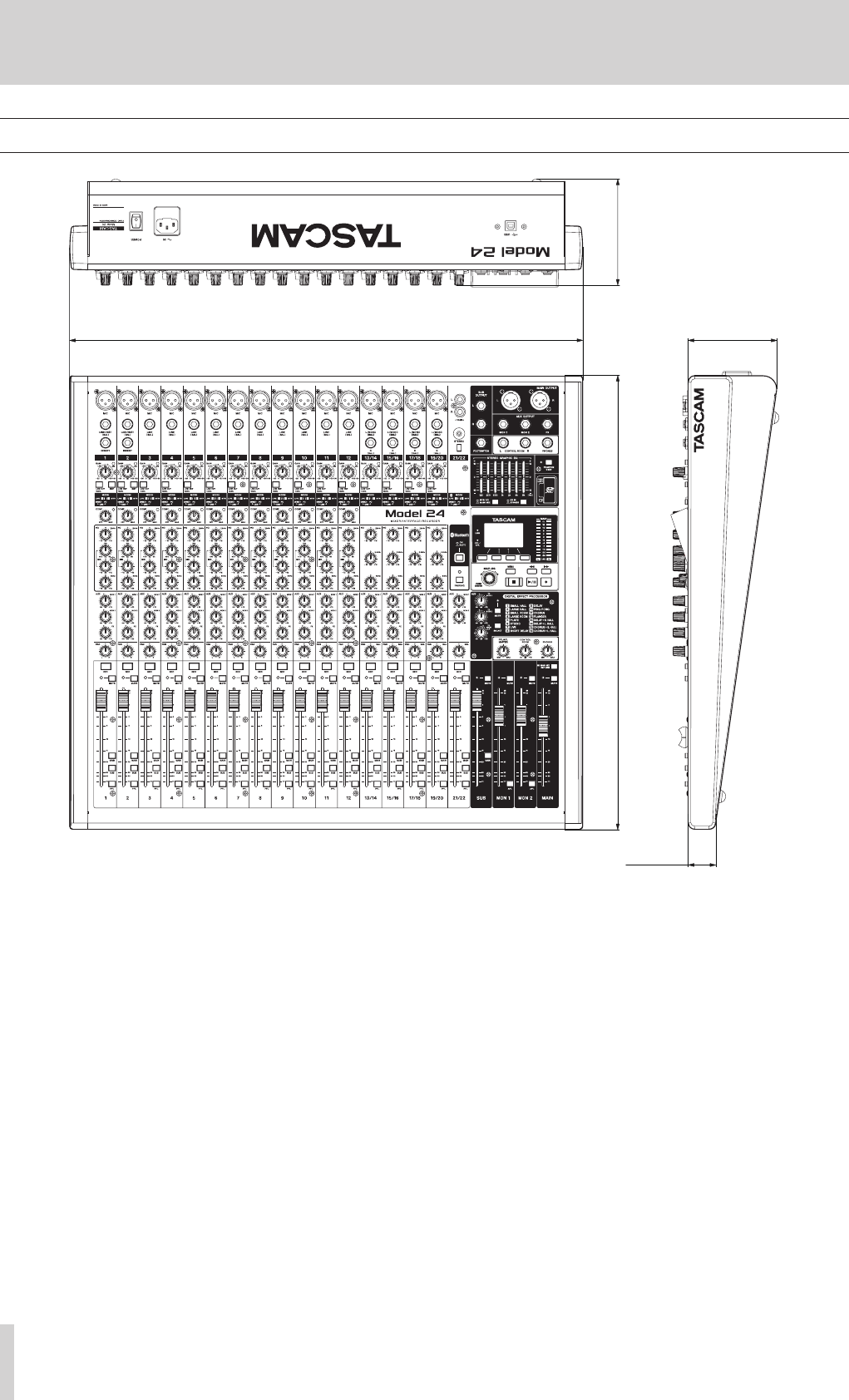
Dimensional drawings
117.4mm
99.9mm
513.0mm
580.0mm
31.5.mm
0Illustrations in this manual might differ in part from the actual product.
0Specifications and external appearance might be changed without notification to improve the product.
TASCAM Model 24 47
13 – Specifications
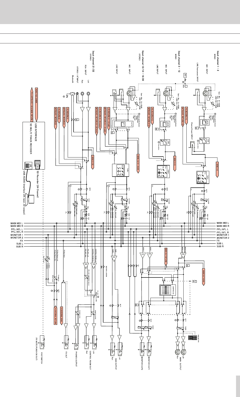
Block diagram

48 TASCAM Model 24
13 – Specifications
Level diagram

無料修理規定(持ち込み修理)
1.
2.
3.
4.
5.
6.
アアアア
✄
✄
保証書
Model 24
✄
✄
Printed in China
ティアック 修 理 セ ンタ ー
この製品の取り扱いなどに関するお問い合わせは
タスカム カスタマーサポート
0570-000-809
0
電話:042-356-9137 / FAX:042-356-9185
故障・修理や保守についてのお問い合わせは
ティアック 修 理 セ ンタ ー
0570-000-501
0
電話:04-2901-1033 / FAX:04-2901-1036
0718.MA-????A
FCC Caution:
This device complies with part 15 of the FCC Rules. Operation is subject to the
following two conditions: (1) This device may not cause harmful interference, and (2)
this device must accept any interference received, including interference that may
cause undesired operation.
Any Changes or modifications not expressly approved by the party responsible for
compliance could void the user's authority to operate the equipment.
Note: This equipment has been tested and found to comply with the limits for a Class
B digital device, pursuant to part 15 of the FCC Rules. These limits are designed to
provide reasonable protection against harmful interference in a residential installation.
This equipment generates uses and can radiate radio frequency energy and, if not
installed and used in accordance with the instructions, may cause harmful interference
to radio communications. However, there is no guarantee that interference will not
occur in a particular installation. If this equipment does cause harmful interference to
radio or television reception, which can be determined by turning the equipment off
and on, the user is encouraged to try to correct the interference by one or more of the
following measures:
-Reorient or relocate the receiving antenna.
-Increase the separation between the equipment and receiver.
-Connect the equipment into an outlet on a circuit different from that to which the
receiver is connected.
-Consult the dealer or an experienced radio/TV technician for help.
The device has been evaluated to meet general RF exposure requirement. The device
can be used in portable exposure condition without restriction.
IC Caution:
This device complies with Industry Canada’s licence-exempt RSSs. Operation is subject to the
following two conditions:
(1)This device may not cause interference; and
(2)This device must accept any interference, including interference that may cause undesired
operation of the device.
Le présent appareil est conforme aux CNR d'Industrie Canada applicables aux apparei ls radio
exempts de licence. L'exploitation est autorisée aux deux conditions suivantes:
(1) l'appareil ne doit pas produire de brouillage, et
(2) l'utilisateur de l'appareil doit accepter tout brouillage radioélectrique subi, même si le
brouillage est susceptible d'en compromettre le fonctionnement.
The device has been evaluated to meet general RF exposure requirement. The device
can be used in portable exposure condition without restriction.
L'appareil a été évalué pour répondre aux exigences générales
d'exposition RF. L'appareil peut être utilisé dans des
conditions d'exposition portables sans restriction.