Contents
- 1. User Manual Partl 1
- 2. User Manual 2
User Manual Partl 1
D00000000A
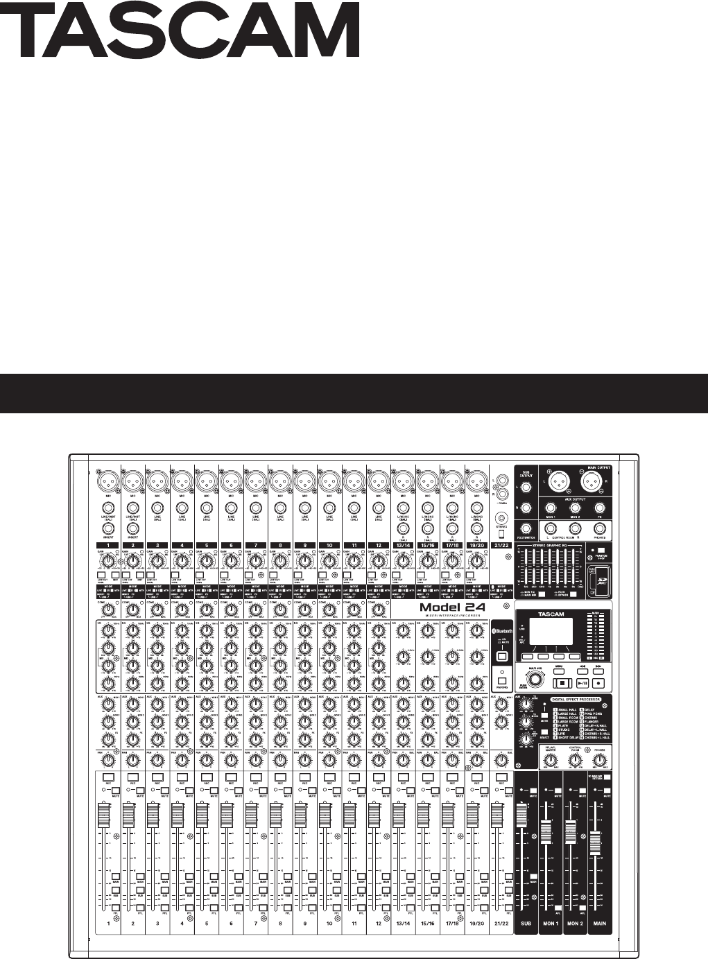
Model 24
Analog Mixer
取扱説明書
2 TASCAM Model 24
Precautions for safe use
V警告 以下の内容を無視して誤った取り扱いをすると、人が死亡または重傷を負う可能性が
想定される内容を示しています。
P
電 源プラグ
をコンセン
トから抜く
万一、異常が起きたら
煙が出た、変なにおいや音がするときは
機器の内部に異物や水などが入ったときは
この機器を落とした、カバーを破損したときは
N
指示
電源プラグにほこりをためない
=
禁止
電源コードを傷つけない
電源コードの上に重い物を載せたり、コードを壁や棚との間に挟み込んだり、本機の下敷きにしない
電 源コードを 加 工したり、 無 理 に曲 げたり、 ねじったり、 引っ張ったり、 熱 器 具 に近 付 けて加 熱したりし
ない
付属の電源コードを他の機器に使用しない
交流100ボルト以外の電圧で使用しない
この機器を設置する場合は、放熱をよくするために、壁や他の機器との間は少し(20cm以上)離して
設置する
ラックなどに入れるときは、機器の天面から1U以上、背面から10cm以上の隙間を空ける
この機器の通風孔などから内部に金属類や燃えやすい物などを差し込む、または落とさない
この機器の通風孔をふさがない
C
禁止
機器の上に花びんや水などが入った容器を置かない
Y
分解禁止
この機器のカバーは絶対に外さない
この機器を改造しない
注意

TASCAM Model 24 3
Precautions for safe use
V注意 以下の内容を無視して誤った取り扱いをすると、人が傷害を負う可能性が想定される
内容および物的損害のみの発生が想定される内容を示しています。
P
電 源プラグ
をコンセン
トから抜く
移動させる場合は、電源のスイッチを切るか、またはスタンバイにし、必ず電源プラグをコンセントか
ら抜き、外部の接続コードを外す
旅行などで長期間この機器を使用しないときやお手入れの際は、安全のため必ず電源プラグをコンセ
ントから抜く
N
指示
オーディオ機器を接続する場合は、各々の機器の取扱説明書をよく読み、電源を切り、説明にしたがっ
て接続する
また、接続は指定のコードを使用する
電源を入れる前には、音量を最小にする
この機器はコンセントの近くに設置し、電源プラグは簡単に手が届くようにする
この機器には、付属の電源コードを使用する
=
禁止
ぐらついた台の上や傾いた所など不安定な場所に置かない
湿気やほこりの多い場所に置かない。風呂、シャワー室では使用しない
調理台や加湿器のそばなど油煙や湯気が当たる場所に置かない
電源プラグを抜くときは、電源コードを引っ張らない
O
禁止
濡れた手で電源プラグを抜き差ししない
V
注意

4 TASCAM Model 24
Contents
Precautions for safe use ................................................................2
1 – Introduction ............................................................................. 6
Features ......................................................................................................................6
Included items ..........................................................................................................6
Conventions used in this manual ...................................................................... 6
Trademarks ................................................................................................................ 7
Precautions for placement and use .................................................................. 7
Notes about power supplies ...............................................................................7
Beware of condensation ....................................................................................... 7
Cleaning the unit ..................................................................................................... 7
About SD cards.........................................................................................................8
Precautions for use ............................................................................................ 8
SD card write protection .................................................................................8
Note about formatting ..................................................................................... 8
Notes about power supplies ...............................................................................8
Bluetooth® ......................................................................................................................................................................................................9
Profiles .................................................................................................................... 9
Codecs .................................................................................................................... 9
Content protection ............................................................................................ 9
Transmission security .......................................................................................9
User registration ......................................................................................................9
アアアアアアアア ....................................................................................................................9
2 – Names and Functions of Parts ................................................ 10
Top panel ................................................................................................................. 10
Analog input jack section ............................................................................ 11
Input channel mixing section ..................................................................... 12
Analog output jack section ......................................................................... 13
Screen operation section ............................................................................. 14
Built-in effects operation section .............................................................. 14
Analog output adjustment section .......................................................... 15
Rear panel ............................................................................................................... 15
Home Screen.......................................................................................................... 16
Meters Screen ........................................................................................................ 16
Meter Screen details ...................................................................................... 17
Menu structure...................................................................................................... 17
Basic MENU screen operations ........................................................................ 18
Menu operation procedures ....................................................................... 18
3 – Preparation ............................................................................19
Connecting other equipment.......................................................................... 19
Connecting microphones ............................................................................ 20
Guitar ................................................................................................................... 20
Connecting electronic devices and other audio equipment .......... 20
Connecting monitor speakers .................................................................... 20
Connecting headphones ............................................................................. 20
Computer connections ................................................................................. 20
Connecting with Bluetooth devices ......................................................... 20
Inserting and removing SD cards ................................................................... 21
Inserting SD cards ........................................................................................... 21
Removing SD cards ........................................................................................ 21
SD card write protection switches ............................................................ 21
Turning the power on and off.......................................................................... 21
Setting the built-in clock date and time ...................................................... 22
Adjusting the display .......................................................................................... 22
Adjusting the display contrast ................................................................... 22
Adjusting the display brightness .............................................................. 22
Preparing an SD card for use ............................................................................ 22
4 – Managing Songs ....................................................................23
Viewing the song list ........................................................................................... 23
Song Operation..................................................................................................... 23
Creating a New Song .......................................................................................... 23
Loading Songs ....................................................................................................... 24
Viewing song information ................................................................................ 24
Deleting songs ...................................................................................................... 24
Protecting/unprotecting songs ...................................................................... 25
Editing song names ............................................................................................. 25
Editing text ........................................................................................................ 25
5 – Basic recording.......................................................................26
Selecting the input source ................................................................................ 26
Setting the MODE switch .................................................................................. 26
Setting phantom power .................................................................................... 26
Monitoring .............................................................................................................. 27
SIG indicators and level meters ....................................................................... 27
Recording ................................................................................................................ 27
Undoing operations ............................................................................................ 28
Undoing the previous operation ............................................................... 28
Using the built-in effects ................................................................................... 28
Setting the built-in effect ............................................................................. 28
6 – Recorder functions .................................................................30
Locate function ..................................................................................................... 30
Changing the playback position ............................................................... 30
Using the direct locate function to locate.............................................. 30
Repeat playback function ................................................................................. 30
Punch in/out function ........................................................................................ 30
Using the footswitch to punch in/out ..................................................... 30
Setting up the footswitch ............................................................................ 31
Setting the footswitch polarity .................................................................. 31
Automatic punch in/out function ................................................................. 31
Setting the punch in/out points ................................................................ 31
Setting a pre roll point .................................................................................. 32
Rehearsing punching in and out ............................................................... 32
Using automatic punching in and out .................................................... 32
7 – Track editing ..........................................................................33
Clearing tracks ....................................................................................................... 33
Importing tracks ................................................................................................... 33
8 – Settings and Information .......................................................34
Viewing information ........................................................................................... 34
CARD Screen ..................................................................................................... 34
SONG Screen ..................................................................................................... 34
FIRMWARE Screen ........................................................................................... 34
Setting the song name format ........................................................................ 34
Setting the WORD item ................................................................................. 34
Restoring factory default settings .................................................................. 35
Formatting SD cards ............................................................................................ 35
Playing WAV files on SD cards
(SD PLAY mode) .................................................................................................... 36
9 –Using a computer to transfer data ..........................................37
Connecting with a Computer .......................................................................... 37
Disconnecting .................................................................................................. 37
Loading WAV files from a computer .............................................................. 38
10 – USB audio interface functions .............................................39
Installing the dedicated software
(Windows only) ..................................................................................................... 39
Installing the Windows dedicated software .......................................... 39
Uninstalling the Windows dedicated software .................................... 40
Opening the Settings Panel (Windows only) ............................................. 40
Windows Settings Panel overview ................................................................. 40
11 – Messages .............................................................................. 41
12 – Troubleshooting ..................................................................43
13 – Specifications ....................................................................... 44
General ..................................................................................................................... 44
Inputs and outputs .............................................................................................. 44
Analog audio input and output ratings .................................................. 44
Control input/output ..................................................................................... 44
Computer system requirements ..................................................................... 45

TASCAM Model 24 5
Contents
Windows ............................................................................................................. 45
Mac ....................................................................................................................... 45
Supported audio drivers .............................................................................. 45
Audio performance ............................................................................................. 45
Bluetooth ................................................................................................................ 45
Other ......................................................................................................................... 45
Dimensional drawings........................................................................................ 46
Block diagram ........................................................................................................ 47
Level diagram ........................................................................................................ 48
6 TASCAM Model 24
1 – Introduction
Thank you very much for purchasing the TASCAM Model 24 Analog
Mixer.
Before using this unit, read this Owner's Manual carefully so that you will
be able to use it correctly and enjoy working with it for many years. After
you have finished reading this manual, please keep it in a safe place for
future reference. You can also download this Owner’s Manual and the
Reference Manual from the TEAC Global Site (http://teac-global.com/).
Features
022 input analog mixer with 22 line and 16 mic inputs
0Multitrack recording and playback with 24-track recording (22 input
channels and MAIN MIX L/R bus)
0USB audio interface functions built-in
o 24 tracks (22 input channels and MAIN MIX L/R bus) can be input
to the computer
o 22 track outputs and computer outputs can be assigned to chan-
nel inputs
o Supports USB 2.0 at up to 48kHz and 24-bit
0Compressors included on channel 1-12 inputs
0100mm faders enable precise adjustments
0High impedance (Hi-Z) inputs on channels 1-2
0Channel inserts (INSERT) on channels 1-2
0Multiple buses include stereo main (MAIN MIX L/R bus), sub (SUB L/R
bus) and monitor (MONITOR OUT 1/2)
03 AUX sends (MON 1/MON 2/FX)
0Input channels have 3-band semi-parametric EQs with adjustable
mid frequencies
0Outputs have a 7-band stereo graphic EQs useful for adjusting the
mix
016 TASCAM preset effects can be used for a variety of applications
0Multitrack recording and playback possible using SD cards
0Bluetooth® audio playback supported
0Punching in and out supported per track (including punching in and
out automatically and with footswitches)
0SD/SDHC cards and SDXC cards up to 128GB supported
Included items
This product includes the following items.
Take care when opening the package to avoid damaging the items. Keep
the box and packing materials for transportation in the future.
Please contact the store where you purchased this unit if any of these
items are missing or have been damaged during transportation.
0Main unit ...............................................................................................................× 1
0Power cord ...........................................................................................................× 1
0Owner's Manual (this document) including warranty ......................... × 1
Conventions used in this manual
In this manual, we use the following conventions:
0When we refer to a button or connector or control on the DR-40, the
typeface looks like this: MENU.
0When we show characters that appear on the display, the typeface
looks like this: MENU.
0The four buttons under the display are called the function buttons.
From left to right, they are shown as buttons F1, F2, F3 and F4.
Moreover the functions show at the bottoms of the screens will be
shown in parentheses after the button names.
Examples: F1 button, F4 button
0SD/SDHC/SDXC memory cards are referred to as “SD cards”.
0Computers, portable audio devices and other equipment connected
to this unit using Bluetooth are called "Bluetooth devices".
0The song that is currently selected is called the “current song”.
0Additional information is introduced in the styles below when
needed:
TIP
We give hints and tips on using the DR-40 when you see this icon.
NOTE
These provide additional explanations and describe special cases.
CAUTION
Failure to follow these instructions could result in damage to equip-
ment or lost data, for example.
VCAUTION
Failure to follow these instructions could result in injury.
TASCAM Model 24 7
1 – Introduction
Trademarks
0TASCAM is a registered trademark of TEAC Corporation.
0SDXC Logo is a trademark of SD-3C, LLC.
0The Bluetooth® word mark and logo are the property of Bluetooth
SIG, Inc. and are used by TEAC Corporation with permission.
0Supply of this product does not convey a license nor imply any right
to distribute MPEG Layer-3 compliant content created with this prod-
uct in revenue-generating broadcast systems (terrestrial, satellite,
cable and/or other distribution channels), streaming applications (via
Internet, intranets and/or other networks), other content distribution
systems (pay-audio or audio-on-demand applications and the like) or
on physical media (compact discs, digital versatile discs, semiconduc-
tor chips, hard drives, memory cards and the like). An independent
license for such use is required. For details, please visit http://mp3li-
censing. com.
0Other company names, product names and logos in this document
are the trademarks or registered trademarks of their respective
owners.
Information is given about products in this manual only for
the purpose of example and does not indicate any guarantees
against infringements of third-party intellectual property
rights and other rights related to them. TEAC Corporation will
bear no responsibility for infringements on third-party intel-
lectual property rights or other liabilities that occur as a result
of the use of this product.
Properties copyrighted by third parties cannot be used for any
purpose other than personal enjoyment and the like without
the permission of the right holders recognized by copyright
law. Always use this equipment properly.
TEAC Corporation will bear no responsibility for rights
infringements committed by users of this product.
Precautions for placement and use
0The operating temperature range of this unit is 5–35 °C.
0Do not install this unit in the following types of locations. Doing so
could make the sound quality worse or cause malfunction.
Locations with frequent vibrations
Next to a window or in another location exposed to direct
sunlight
Near heating equipment or in other locations that become very
hot
Extremely cold places
Places with bad ventilation or high humidity
Very dusty places
0To enable good heat dissipation, do not place anything on top of the
unit.
0Do not place this unit on top of a power amplifier or other device
that generates heat.
Notes about power supplies
0Insert the included power cord all the way into the AC IN connector.
0Do not connect a power supply other than one that is AC100V
(50-60Hz).
0Hold the power cord by its plug when connecting or disconnecting
it.
Beware of condensation
Condensation could occur if the unit is moved from a cold place to a
warm place, it is used immediately after a cold room has been heated
or it is otherwise exposed to a sudden temperature change. To prevent
this, or if this occurs, let the unit sit for one or two hours at the new room
temperature before using it.
Cleaning the unit
Use a dry soft cloth to wipe the unit clean. Do not wipe with chemical
cleaning cloths, thinner, alcohol or other chemical agents. Doing so
could damage the surface or cause discoloration.
8 TASCAM Model 24
1 – Introduction
About SD cards
This unit uses SD cards for recording and playback.
A list of SD cards that have been confirmed for use with this unit can be
found on our web site. Please access to a product page of this product
from the TEAC Global Site (http://teac-global.com) to find the list or
contact the TASCAM customer support service. Please view the page for
this model. You can also contact TASCAM customer support.
Precautions for use
SD cards are delicate media.
In order to avoid damaging SD cards, please take the following precau-
tions when handling them.
0Do not leave them in extremely hot or cold places.
0Do not leave them in extremely humid places.
0Do not let them get wet.
0Do not put things on top of them or twist them.
0Do not hit them.
0Do not remove or insert them during recording, playback, data trans-
mission or other access.
0When transporting them, put them into cases, for example.
SD card write protection
This unit writes track information to the media in order to improve
operation performance. Since track information cannot be written to
SD cards that are write-protected, the amount of time needed to read
media will become longer, for example.
Note about formatting
SD cards formatted by this unit are optimized to improve performance
during recording. Use this unit to format the SD cards to be used with it.
Errors might occur when recording with this unit using an SD card for-
matted by a computer or other device.
Notes about power supplies
0
o
o
201:-171111
0
0
o
o
本機使用上の注意
0
0
0

TASCAM Model 24 9
1 – Introduction
Bluetooth®
This unit has a built-in Bluetooth audio receiver, and can output sound
played on a computer or portable audio device that supports Bluetooth
(Bluetooth device).
CAUTION
The Bluetooth function of this unit is not guaranteed to enable con-
nection or operation with all Bluetooth devices.
Profiles
This unit supports the following Bluetooth profiles.
0A2DPアAdvanced Audio Distribution Profileア
In order to transfer audio by Bluetooth, the Bluetooth device must sup-
port A2DP.
Even if a Bluetooth device supports the same profiles, though, its func-
tions might differ according to its specifications.
Codecs
This unit supports the following codecs. It will automatically select one
of them during audio transfer.
0SBC
0AAC
The unit will select the appropriate codec to use according to the
codec compatibility of the other Bluetooth device and communication
conditions.
NOTE
i You cannot select the codec to be used by pressing a button, for
example.
i Due to characteristics of Bluetooth wireless technology, playback
from a Bluetooth device will be slightly delayed compared to play-
back from this unit.
Content protection
This unit supports SCMS-T as a form of content protection when trans-
mitting audio, so it can play protected audio.
Transmission security
This unit supports security functions during Bluetooth transmission in
accordance with the Bluetooth standard specifications, but it does not
guarantee the privacy of such transmissions.
TEAC CORPORATION will bear no responsibility should an information
leak occur during transmission by Bluetooth.
User registration
Customers in the USA, please visit the TASCAM website (http://tascam.
com/) to register as a user online.
https://tascam.jp/jp/login
アフターサービス
00この製品には,0保証書が添付(巻末に記載)されています。0大切
に保管してください。0万が一販売店の捺印やご購入日の記載が
ない場合は,0無料修理保証の対象外になりますので,0ご購入時のレ
シートなどご購入店・ご購入日が確認できる物を一緒に保管してく
ださい。
00保証期間は,0お買い上げの日より1年です。0保証期間中は,0記載内
容によりティアック修理センター(巻末に記載)が無償修理致しま
す。0For0details0about0each0operation0mode,0see0.
00保証期間経過後,0または保証書を提示されない場合の修理などに
ついては,0お買い上げの販売店またはティアック修理センター(巻
末に記載)にご相談ください。0修理によって機能を維持できる場
合は,0お客様のご要望により有料修理致します。
00万一,0故障が発生した場合は使用を中止し,0必ず電源プラグをコン
セントから抜いて,0お買い上げの販売店またはティアック修理セン
ター(巻末に記載)までご連絡ください。0修理を依頼される場合は,0
次の内容をお知らせください。
なお,0本機の故障,0もしくは不具合により発生した付随的損害(録
音内容などの補償)の責については,0ご容赦ください。
本機を使ったシステム内の記録メディアなどの記憶内容を消失し
た場合の修復に関しては,0補償を含めて当社は責任を負いかねま
す。
o 型名,0型番(Model024)
o 製造番号(Serial0No.)
o 故障の症状(できるだけ詳しく)
o お買い上げの年月日
o お買い上げの販売店名
00お問い合わせ先については,0巻末をご参照ください。
00本機を廃棄する場合に必要となる収集費などの費用は,0お客様の
ご負担 になります。
10 TASCAM Model 24
2 – Names and Functions of Parts
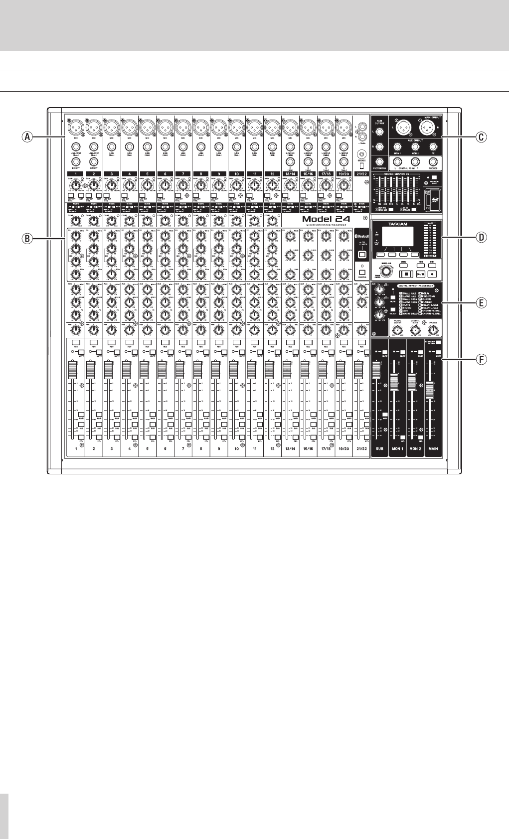
Top panel
a Analog input jack section
Use this section to connect the input jacks for each channel and to
adjust the input levels.
b Input channel mixing section
Use this section to choose input sources for each channel, adjust
compressors and equalizers, and set levels sent to each bus (MAIN
MIX L/R, PFL/AFL L/R, MONITOR OUT 1/2, FX, SUB L/R).
c Analog output jack section
Use this section to connect the output jacks and adjust the output
equalizer.
d Screen operation section
Use this section to operate the meter, home and MENU screens shown
on the display.
e Built-in effects operation section
Operate the built-in effects and adjust the output levels for each out-
put in this section.
f Analog output adjustment section
Adjust the output levels from the MAIN OUTPUT, SUB OUTPUT, MON
1 and MON 2 jacks in this section.
TASCAM Model 24 11
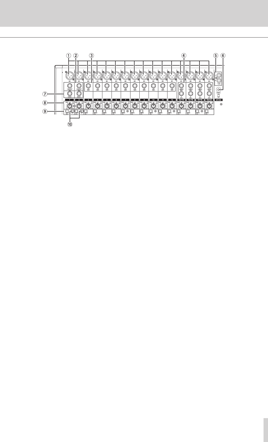
2 – Names and Functions of Parts
Analog input jack section
1 MIC input jacks (1-12, 13/14-19/20)
These are balanced XLR jacks for mic input.
o XLR (1: GND, 2: HOT, 3: COLD)
2 LINE/INST (BAL) mono input jacks (1-2)
These standard TRS jacks are mono line inputs.
Use the INST switches on the top of the unit to enable balanced line
(MIC/LINE) input or unbalanced (INST) input.
When directly connecting a guitar, bass or other instrument, set the
INST switch to on.
o TRS (Tip: HOT, Ring: COLD, Sleeve: GND)
3 LINE (BAL) input jacks (3-12)
These standard TRS jacks are line inputs.
o TRS (Tip: HOT, Ring: COLD, Sleeve: GND)
4 L/MONO (BAL)/R (BAL) stereo input jacks (13/14-19/20)
These standard TRS jacks are stereo line inputs.
If only the L/MONO (BAL) jack in a pair is connected, the same sig-
nal was be sent to both left and right channels.
o TRS (Tip: HOT, Ring: COLD, Sleeve: GND)
5 −10dBu (external input) jacks (21/22, RCA pin)
These RCA pin jacks are analog line outputs.
6 STEREO input jack (21/22, stereo mini)
This stereo mini jack is a line input jack.
Use this to connect with the line output jack of a tablet or other
external device.
7 INSERT jacks (1-2, standard)
Use these standard TRS jacks to connect external devices (effects).
o TRS (Tip: SEND, Ring: RETURN, Sleeve: GND)
8 GAIN knobs and SIG indicators (1-12, 13/14-19/20)
Use the GAIN knobs to adjust the input levels of each channel.
When the MODE switch is set to LIVE or PC for a channel, its SIG
indicator will light green when a signal is input (−32 dB or higher).
9 LOW CUT switches (1-12, 13/14-19/20)
Turn this switch on to enable low cut filters that cut noise and other
sounds at low frequencies.
0 INST switches (1-2)
Set according to the LINE/INST (BAL) input jack input sources.
Turn the INST switch on when connecting an electric guitar, electric
bass or other equipment with high output impedance.
Turn the INST switch off when connecting electronic instruments,
audio devices, mics and other equipment.
12 TASCAM Model 24
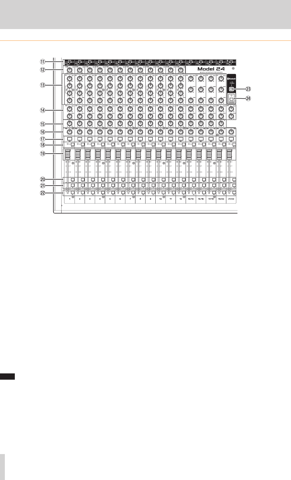
2–Names and Functions of Parts
Input channel mixing section
q MODE switches (1-12, 13/14-19/20, 21/22)
Use these to select the input source for each channel.(see “Setting
the MODE switch” on page 26)
w COMP knobs and indicators (1-12)
Use these knobs to adjust the compression of the signals input to
each channel.
When compression is activated, the COMP indicators light.
e EQ knobs (1-12, 13/14-19/20)
i Use these to boost and attenuate the HIGH, MID and LOW bands
of each channel.
Setting range: ±15 dB
i The cutoff frequencies of the MID bands can be set for channels
1-12.
Setting range: 100Hz – 8kHz (default: 700Hz)
r MON 1/MON 2 knobs (1-12, 13/14-19/20, 21/22)
Use these to adjust the levels of signals sent to the MONITOR OUT 1/2
buses.
t FX knobs (1-12, 13/14-19/20)
Use to adjust the levels of the signals sent to the FX bus.
y PAN knobs (1-12, 13/14-19/20, 21/22)
Use to adjust the stereo positions of the signals input to each
channel.
NOTE
i When PAN knobs are centered (C), signals are reduced by 3 dB and
sent to both left and right MAIN MIX L/R buses.
i When a PAN knob is turned all the way to the left (L), that channel
signal is sent only to the left MAIN MIX L/R bus. It is not sent to the
right bus.
i When a PAN knob is turned all the way to the right (R), that channel
signal is sent only to the right MAIN MIX L/R bus. It is not sent to the
left bus.
u REC buttons and indicators (1-12, 13/14-19/20, 21/22)
Use these to select the channels to record to the SD card.
i MUTE switches and indicators (1-12, 13/14-19/20, 21/22)
When these switches are on (MUTE indicator lit), those channels are
muted.
o Channel faders (1-12, 13/14-19/20, 21/22)
Use these to adjust the send levels of channel signals.
p MAIN switches (1-12, 13/14-19/20, 21/22)
Turn these switches on to send channel signals to the MAIN MIX L/R
bus.
a SUB switches (1-12, 13/14-19/20, 21/22)
Turn these switches on to send channel signals to the SUB L/R bus.
s PFL switches (1-12, 13/14-19/20, 21/22)
Turn these switches on to send channel signals to the PFL/AFL L/R
bus.
d ON/MUTE switches
Turn this switch on to input audio from a paired Bluetooth device.
f PAIRING button and indicator
Press and hold this button to activate Bluetooth pairing mode.
Press when pairing to end pairing mode.(see “Connecting with Blue-
tooth devices” on page 20)
TASCAM Model 24 13
2 – Names and Functions of Parts
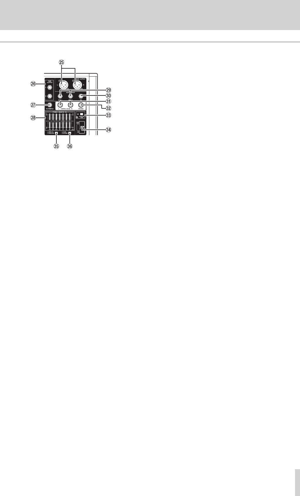
Analog output jack section
g MAIN OUTPUT L/R jacks
These analog outputs are XLR jacks.
o XLR (1: GND, 2: HOT, 3: COLD)
h SUB OUTPUT L/R jacks
These standard TS jacks are stereo analog outputs.
o TS (Tip: HOT, Sleeve: GND)
j FOOTSWITCH jack
This standard TS jack is for connecting a footswitch.
o TS (Tip: HOT, Sleeve: GND)
k STEREO GRAPHIC EQ faders
This 7-band graphic equalizer affects signals output from the MAIN
OUTPUT and AUX OUTPUT MON 1/2 jacks.
l AUX OUTPUT MON 1/2 jacks
These standard TS jacks are analog outputs.
o TS (Tip: HOT, Sleeve: GND)
; FX OUTPUT jack
This standard TS jack is an analog output.
When an external effect is connected, signals will not be sent to the
built-in effect.
When using an external effect, turn the built-in effect off.
o TS (Tip: HOT, Sleeve: GND)
z CONTROL ROOM L/R jacks
These standard TS jacks are stereo analog outputs.
Use these to monitor signals from the MAIN MIX L/R bus or PFL/AFL
L/R bus.
o TS (Tip: HOT, Sleeve: GND)
x PHONES jack
Use this standard stereo jack to connect stereo headphones. Use an
adapter to connect headphones with a mini plug.
Use this to monitor signals from the MAIN MIX L/R bus or PFL/AFL L/R
bus.
c PHANTOM +48V switch and indicator
Use this switch to supply +48V phantom power to the 1-2, 3-12 and
13/14-19/20 MIC input jacks on the top of the unit.
The indicator lights when the PHANTOM +48V switch is set to on.
Connect mics and output devices after turning phantom power on.
Before turning phantom power off, disconnect mics and output
devices.(see “Setting phantom power” on page 26)
v SD card slot
Insert SD cards in these slots.(see “Inserting and removing SD cards”
on page 21)
b MON 1/2/MAIN MIX switch
Set which output signals are affected by the equalizer.
n EQ IN/BYPASS switch
When this switch is on, the equalizer will affect the output signals set
with the MON 1/2/MAIN MIX switch.
14 TASCAM Model 24
2 – Names and Functions of Parts
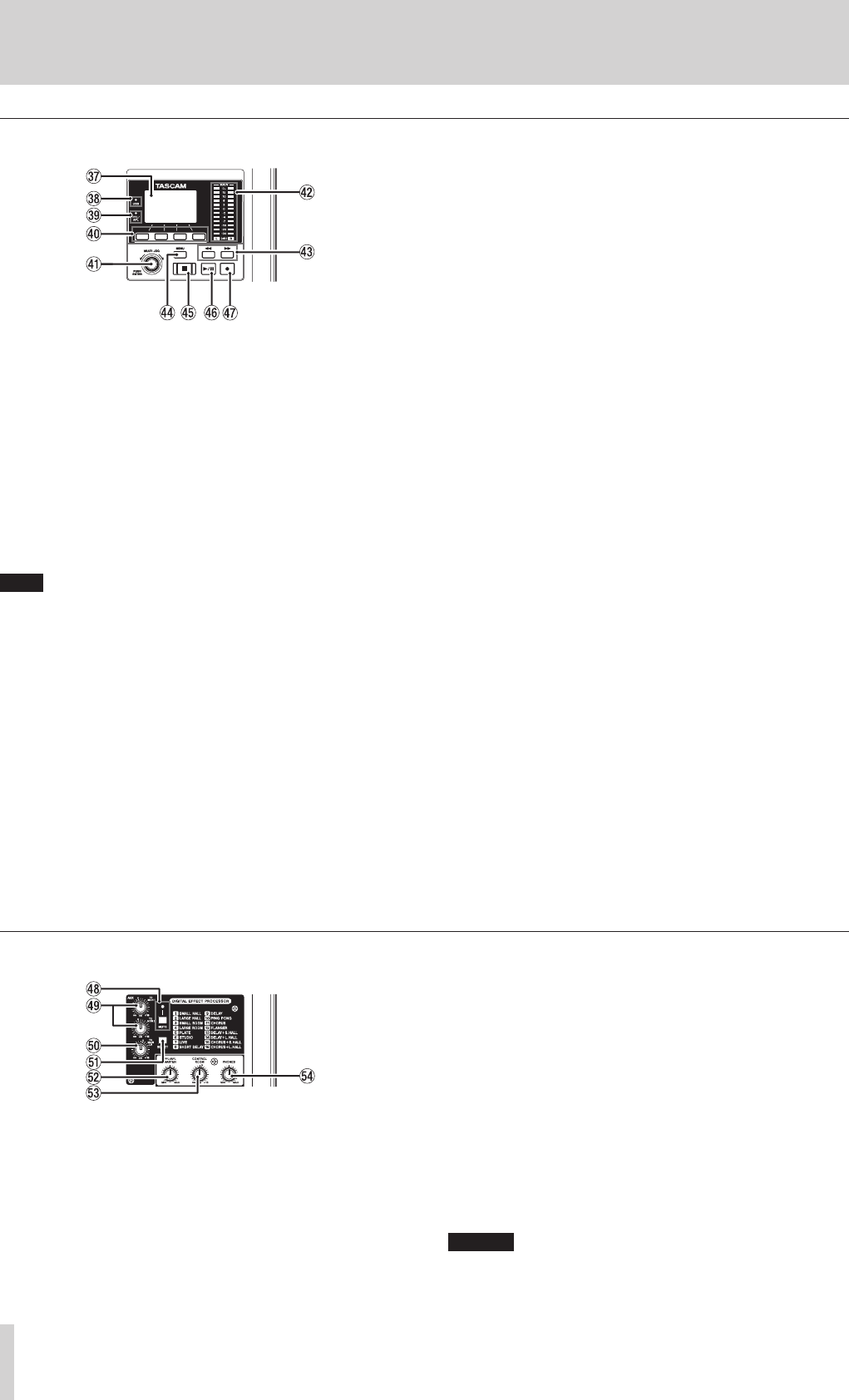
Screen operation section
m Display
Shows a variety of information.
, USB indicator
This lights when the USB connection is working.
. PFL/AFL indicator
This indicator lights when a channel PFL switch is on or when the
MON 1/MON 2 fader AFL switch is on.
/ Function buttons
The functions of these buttons change depending on the screen
shown on the display. The functions shown at the bottom of the dis-
play are the currently assigned functions.
NOTE
For convenience, the four buttons under the display are called the
function buttons in this manual. From left to right, they are called the
F1, F2, F3 and F4 buttons.
! MULTI JOG dial
This dial functions as a dial when turned and as a button when
pressed.
Dial functions
i Turn when the Home Screen is open to move the file playback
position.(see “Locate function” on page 30)
i When a MENU Screen is open, turn to select items and change set-
ting values.(see “Basic MENU screen operations” on page 18)
Button function
i Press when the Home Screen is open to designate a locate point.
(see “Locate function” on page 30)
i When a Menu Screen is open, press to confirm selections and set-
tings (ENTER button function).
@ Output level indicators
These are output level indicators for the MAIN OUTPUT jacks.
# m/, buttons
i When stopped and during playback, press and hold these buttons
to search backward/forward.
i When the Home Screen is open, press the m button to locate
to the beginning of the current song (00:00:00, which is the zero
point).
i When the Home Screen is open, press the , button to locate to
the end of the current song.
i While pressing the 8 button, press the m button to locate to
the point where recording last started.
i While pressing the 8 button, press the , button to locate to
the point where recording last stopped.
i If the current song has auto punch in or out points set, you can
also locate to those points.
i When the SD PLAY Screen is in playback state, press
to skip a file.(see “Playing WAV files on SD cards
(SD PLAY mode)” on page 36)
$ MENU button
i When the Meter Screen is open, press to open the Home Screen.
i When the Home Screen is open, press to open the MENU Screen.
(see “Menu structure” on page 17) and(see “Basic MENU screen
operations” on page 18)
i When the MENU Screen or a menu item settings screen is open,
press to return to the Home Screen.
% 8 button/indicator
Press to stop playback or recording.
This button lights when stopped.
Press this button when paused to return to the beginning of the song
or file.
^ 7/9 button/indicator
Press this button to start playback.
This button lights during playback and recording.
This button blinks when paused.
& 0 button/indicator
Press this button to start recording.
This button lights during recording.
Press this button during playback to start recording (punch in).(see
“Automatic punch in/out function” on page 31)
Built-in effects operation section
* MUTE switch/indicator
When the MUTE switch is on (MUTE indicator lit), the signal from
the built-in effect is muted.
( TO MON 1/TO MON 2 knobs
Use these to adjust the levels of signals sent from the built-in effects
to the MONITOR OUT 1/2 buses.
) TO MAIN LR knob
Use these to adjust the levels of signals sent from the built-in effects
to the MAIN MIX L/R buses.
Q SELECT button
Open the EFFECT Screen and make built-in effect settings.(see “Using
the built-in effects” on page 28)
The built-in effect return signal is return to the MAIN MIX L/R bus and
MONITOR OUT 1/2 buses.
W PFL/AFL MASTER knob
Use these to adjust the send level from the PFL/AFL L/R bus.
E CONTROL ROOM knob
Use to adjust the output levels of the CONTROL ROOM jacks.
R PHONES knob
Use this to adjust the headphone output level.
CAUTION
Before connecting headphones, minimize the volume with the
PHONES knob. Failure to do so could result in a sudden loud noise
that could harm hearing, for example.

TASCAM Model 24 15
2 – Names and Functions of Parts
Analog output adjustment section
T MUTE switches and indicators (SUB, MON 1, MON 2,
MAIN)
When MUTE switches are on (MUTE indicators lit), signals to the
corresponding output jacks are muted.
Y MAIN switch
When this switch is on, the SUB OUTPUT L/R jack output signal is
sent to the MAIN MIX L/R bus.
U AFL switches (MON 1/MON 2)
When these switches are on, the AUX OUTPUT MON 1/2 jack out-
put signals are sent to the PFL/AFL L/R bus.
I SD MAIN MIX RETURN switch
When this switch is on, signals from the USB interface and SD card
can be mixed into the MAIN MIX L/R bus.
O SUB fader
Use to adjust the output level of the SUB OUTPUT jacks.
P MON 1/MON 2 fader
Use to adjust the output levels of the AUX OUTPUT MON 1/2 jacks.
A MAIN fader
Use to adjust the output level of the MAIN OUTPUT jacks.
Rear panel
S USB port
This is a B-type USB port. Use a USB cable (Type-A to Type-B) to con-
nect the unit to a computer.(see “Connecting with a Computer” on
page 37)
ATTENTION
The unit should be connected directly to the computer, not through
a USB hub.
D AC IN connector
Connect the included power cord here.
F POWER switch
Press to turn the unit on and off.
ATTENTION
Before turning the unit on, lower the volumes of connected equip-
ment to their minimum levels.
Failure to do so might cause sudden loud noises, which could harm
your hearing or result in other trouble.
NOTE
Do not do this when the unit is operating (including recording, play-
ing back or writing data to an SD card). Doing so could cause proper
recording to fail and recorded data to be lost.
16 TASCAM Model 24
2 – Names and Functions of Parts
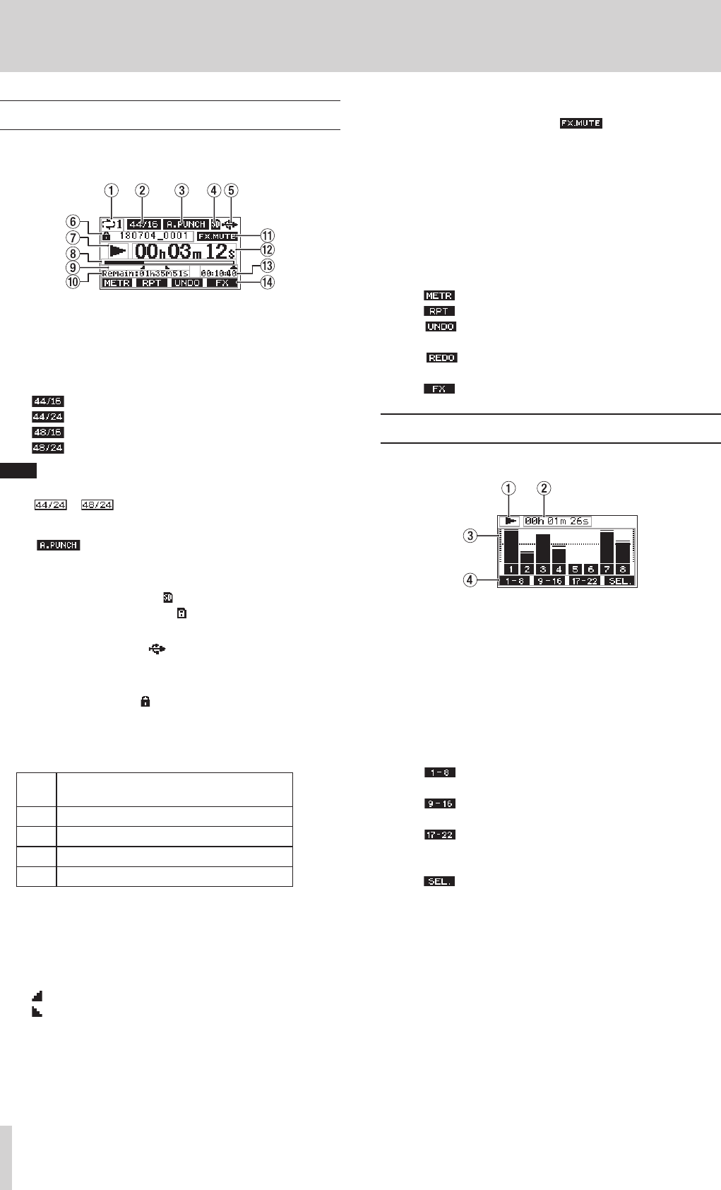
Home Screen
When the Meter Screen is open, press the MENU button to open the
Home Screen.
1 Repeat playback status
An icon appears when the repeat playback function is on.(see “Repeat
playback function” on page 30)
2 Song format
This shows the current song file format.
44.1kHz, 16bit
44.1kHz, 24bit
48kHz, 16bit
48kHz, 24bit
NOTE
If no song is loaded, the operation format of the unit will be shown
like or .
3 Automatic punch in/out function on/off status
The icon appears when the automatic punch in/out func-
tion is on.(see “Automatic punch in/out function” on page 31)
4 SD card present status
When an SD card is loaded, the icon appears.
When an SD card is protected, the icon appears.
5 USB connection status
During USB connection, the icon appears.
6 Song name
This shows the name of the current song.
If a song is protected, an icon appears before the file name.(see
“Protecting/unprotecting songs” on page 25)
7 Transport status
This icon shows the recorder operation status.
Indi-
cator Meaning
8Stopped at the beginning of the file
9Paused
0Recording
7Playback
8 Playback position
The current playback position is shown by a bar.
9 Automatic punch in/out point setting status
When the automatic punch in/out function is on, these show the sta-
tus of automatic punch in/out point setting.
Punch in point
Punch out point
0 Remaining time
The remaining time available for recording on the SD card is shown (in
hours: minutes: seconds).
q Built-in effect on/off status
When the built-in effect is on, the icon appears.(see “Using
the built-in effects” on page 28)
w Recorder time counter
This shows the elapsed time from the beginning of the song.
e Song length
This shows the length of the current song (in hours: minutes:
seconds).
r Function button functions
This shows the functions assigned to the function button on the
Home Screen.
i F1 button: This opens the Meter Screen.
i F2 button: This turns the repeat playback function on/off.
i F3 button: This returns to the state before the previous
operation.
i F3 button: This restores the state after the previous
operation.
i F4 button: This turns the built-in effect on/off.
Meters Screen
This shows the levels of the signals being input to the unit.
1 Transport status
This icon shows the recorder operation status.
2 Recorder time counter
This shows the elapsed time from the beginning of the song.
3 Track level meters
These show the signal levels of each channel.
4 Function button functions
This shows the functions assigned to the function button on the
Meter Screen.
i F1 Press to show the level meters for channel 1–8 sig-
nals on the Meter Screen.
i F2 Press to show the level meters for channel 9–16
signals on the Meter Screen.
i F3 Press to show the level meters for channel 17–22
and MAIN MIX L/R bus signals on the Meter
Screen.
i F4 Press to change the input sources shown on the
Meter Screen.
TASCAM Model 24 17
2 – Names and Functions of Parts
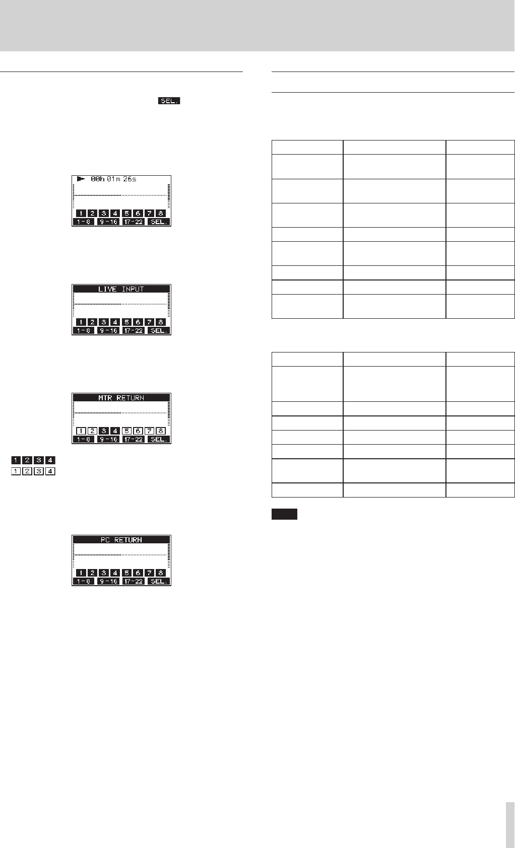
Meter Screen details
When the Meter Screen is open, press the F4 button to change
the signal sources shown by the meters.
Channel input level screens
Depending on the MODE switch setting, the signal levels set for each
channel are shown by the level meters.
LIVE INPUT Screen
These level meters show the levels of the signals being input to the input
jacks.
MTR RETURN Screen
These level meters show the playback signal levels of songs recorded on
SD cards.
Channels that have recording data in the song
Channels that do not have recording data in the song
PC RETURN Screen
These level meters show output signals from a computer when used as a
USB audio interface.
Menu structure
When the Home Screen is open, press the MENU button to open the
MENU Screen.
The various menu items are as follows.
Menu item Function Page
SONG Work with songs on an SD
card see page 24
TRACK CLEAR Clear specific tracks or all
tracks see page 33
AUTO PUNCH Set the auto punch in/out
function see page 31
A.PUNCH PRE ROLL Set the pre-roll point see page 32
IMPORT Import chosen WAV files to
song tracks see page 33
SYSTEM Open the SYSTEM Screen
SD PLAY Play WAV files on an SD card see page 36
STORAGE SD cards can be accessed
from a computer see page 37
On the MENU Screen, select SYSTEM to open the SYSTEM Screen.
The menu items on the SYSTEM Screen are as follows.
Menu item Function Page
INFORMATION
View SD card information,
song information and the
firmware version
see page 34
DATE/TIME Date and time settings see page 22
SONG NAME Set the song name format. see page 34
DISPLAY Adjust the display see page 22
FOOTSW Make footswitch settings see page 31
INITIALIZE Restore factory default
settings see page 35
MEDIA FORMAT Format the SD card see page 35
NOTE
The settings for all menu items are retained even when the unit is
turned off.
18 TASCAM Model 24
2 – Names and Functions of Parts
Basic MENU screen operations
After using the MENU button to open the MENU Screen, it can be oper-
ated in the following manner.
This is an overview of basic operations. Function button assignments
differ according to the screen shown on the display.
Selecting items (moving vertically on a page):
Turn the MULTI JOG dial.
Confirming a selected item:
Press the MULTI JOG dial (ENTER button function).
Opening a submenu from a page:
Press the MULTI JOG dial.
Going back one step in a menu:
Press the F1 button.
Returning to the Home Screen from a MENU Screen:
Press the F1 button.
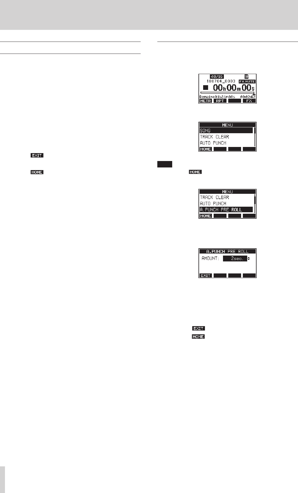
Menu operation procedures
This explanation uses an example of setting the pre-roll point.
1. Press the MENU button to open the Home Screen.
2. Press the MENU button to open the MENU Screen.
NOTE
Press the F1 button to return to the Home Screen.
3. Turn the MULTI JOG dial to select the menu item.
A.PUNCH PRE ROLL selected
4. Press the MULTI JOG dial to open the settings screen.
A.PUNCH PRE ROLL Screen open
5. Turn the MULTI JOG dial to change the setting.
6. To set another item on the same screen, press the MULTI JOG dial
to move the cursor to the next setting.
7. Repeat steps 5 to 6 as necessary to set other items.
8. Press the F1 button to return to the MENU Screen.
9. Press the F1 button to return to the Home Screen.
TASCAM Model 24 19
3 – Preparation
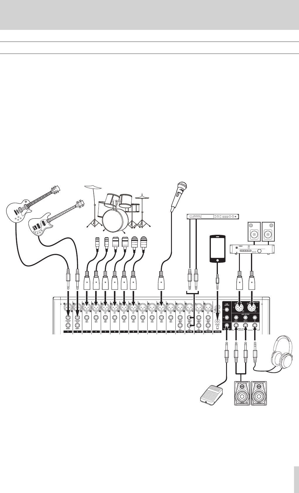
Connecting other equipment
This is an example of Model 24 connections.
Precautions before making connections
0Carefully read the operation manuals of the devices to be connected and then connect them correctly.
0Before making connections, turn this unit and all equipment to be connected off (standby).
0Install all connected devices, including this unit, so that they are powered from the same line. When using a power strip or similar device, be sure to
use one that has high current capacity (thick cable) in order to minimize fluctuations in power voltage.
0Before connecting audio equipment, set the following knobs and faders to their lowest values. Failure to do so could cause sudden loud noises from
monitoring equipment, and this could damage the equipment or harm hearing.
o GAIN knobs (channels 1-12, 13/14-19/20)
o Channel faders (channels 1-12, 13/14-19/20, 21/22)
o SUB fader
o MON 1/MON 2 faders
o MAIN fader
o CONTROL ROOM knob
o PHONES knob
Examples of connections to a Model 24
20 TASCAM Model 24
3 – Preparation
Connecting microphones
Dynamic mics
Connect to MIC input jacks.
Condenser mics
When using a condenser microphone that requires phantom power,
connect it to a MIC input jack and then turn the PHANTOM +48V
switch on.(see “Setting phantom power” on page 26)
The PHANTOM +48V indicator lights when the PHANTOM +48V
switch is on.
Guitar
When connecting a guitar or bass guitar directly to this unit, use the MIC
jacks on channels 1-2 and turn the INST switch on for that jack.
Connecting electronic devices and other audio
equipment
Use the following inputs to connect electronic devices and other audio
equipment.
o LINE/INST (BAL) input jacks
o LINE (BAL) input jacks
o L/MONO (BAL)/R (BAL) input jacks
o −10dBu input jacks
o STEREO input jack
Connecting monitor speakers
Connect monitor speakers (powered speakers or an amplifier and
speaker system) to the CONTROL ROOM L/R jacks.
Depending on the PFL switch and AFL switch settings, signals from the
MAIN MIX L/R bus and PFL/AFL L/R bus can be monitored
Use the CONTROL ROOM knob to adjust the speaker volume.
Connecting headphones
Connect headphones to the PHONES jack (standard stereo).
Depending on the PFL switch and AFL switch settings, signals from the
MAIN MIX L/R bus and PFL/AFL L/R bus can be monitored
CAUTION
Before connecting headphones, minimize the volume with the
PHONES knob. Failure to do so could result in a sudden loud noise
that could harm hearing, for example.
Computer connections
Use a commercially-available Type-A-Type-B USB cable to connect the
unit to a computer USB 2.0 port.
When the USB connection is working, the USB indicator in the screen
operation section lights.
ATTENTION
The unit should be connected directly with the computer instead of
via a USB hub.
Connecting with Bluetooth devices
This unit can output sound from a computer, portable audio device or
other equipment that supports Bluetooth (A2DP).
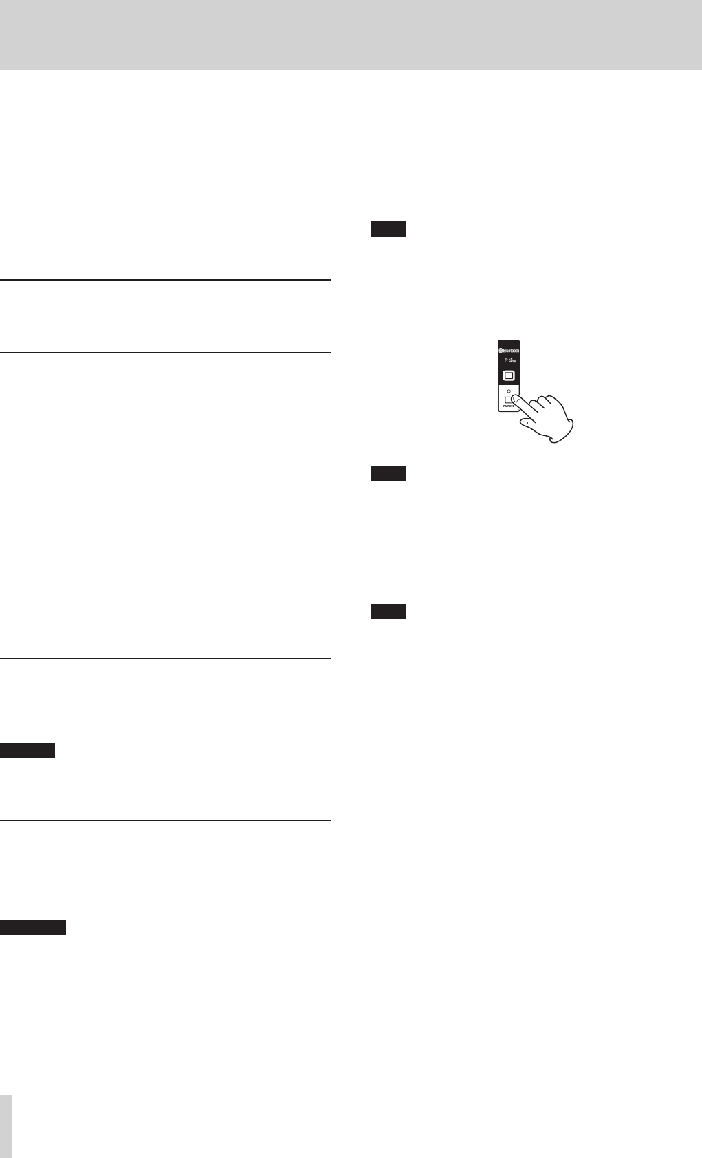
Pairing
Follow the procedures below to enable communication with a Bluetooth
device.
NOTE
Pairing also requires operation of the Bluetooth device.
Refer to the operation manual of the Bluetooth device for procedures.
1. Press the ON/MUTE switch to unmute.
2. Confirm that the PAIRING indicator on the unit is blinking. If the
PAIRING indicator is unlit, press the PAIRING button.
NOTE
When the unit is turned on, it automatically becomes ready for pair-
ing. If 2 minutes pass in pairing mode, it will end. Press this button to
reactivate pairing mode when it is disabled.
3. Select "Model 24" (this unit) on the other Bluetooth device.
When pairing succeeds, the PAIRING indicator will stop blink-
ing and remain lit, and connection with the other device will be
complete.
NOTE
i Some older Bluetooth devices require the input of a passkey. Enter
"0000" in such cases.
i Pairing will automatically end if connection is not confirmed within
two minutes.
i When this unit is turned on, it will automatically try to connect with
the Bluetooth device to which it was previously connected. At this
time, pairing will automatically end after five minutes if connection
is not possible because that Bluetooth device is not turned on or its
Bluetooth function is turned off.
Unpairing
The Bluetooth device that is currently connected can be unpaired from
the unit.
1. Press and hold the PAIRING button for at least two seconds.
2. This ends the pairing. The PAIRING indicator will start blinking and
the unit will be ready to pair.
TASCAM Model 24 21
3 – Preparation
Inserting and removing SD cards
Inserting SD cards
Insert an SD card into an SD card slot on the top of the unit to enable
playback and recording by this unit.
NOTE
SD cards can be inserted whether or not the unit is on or off.
1. Open the SD card slot cover.
2. The SD card label should be facing left and the connector should
be inserted down.
3. Close the SD card slot cover.
Removing SD cards
Turn the unit off or stop operation before removing an SD card.
CAUTION
Do not remove an SD card when the unit is operating (including play-
ing back or recording). Doing so could cause proper recording to fail,
data to be lost, and sudden loud noises from monitoring equipment,
which might damage the equipment, harm hearing or cause other
trouble.
1. Press the SD card in gently to make it to come up.
2. Pull the SD card out.
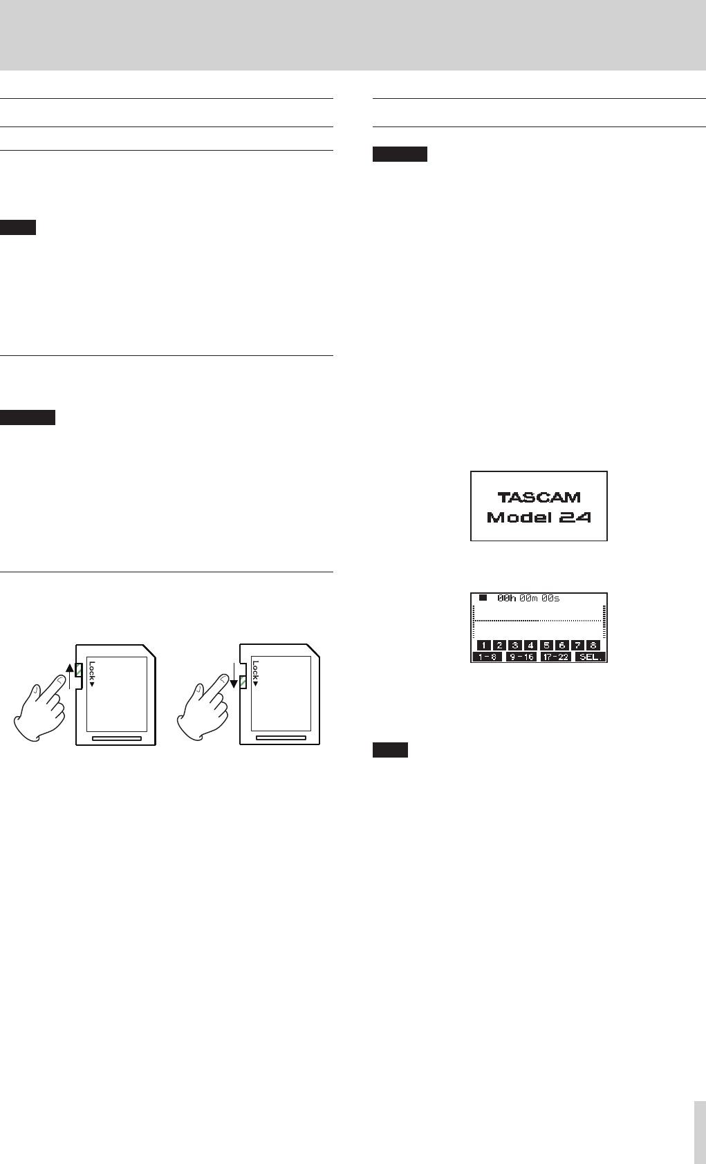
SD card write protection switches
SD cards have write-protection switches that prevent writing new data
to them.
If you slide the write-protection switch to the LOCK position, writing will
not be possible. Move the write-protection switch to the unlocked posi-
tion in order to record, erase and otherwise edit data on the card.
Turning the power on and off
CAUTION
i Turn down the volume of the sound system connected to the unit
before starting up or shutting down the unit.
i Do not wear connected headphones when turning the unit on and
off. Loud noises could damage the speakers or harm your hearing.
Before turning the power on
1. Make the following settings on the top of the unit.
o EQ knobs w center values
o Other knobs w all the way left
o Faders w all the way down
o Switches w off (not pushed in)
2. Minimize the output levels of audio sources and input levels of
amplifiers connected to this unit.
Turning the power on
1. Use the POWER switch on the back of the unit to turn its power
on.
Startup screen
Meter Screen
After the unit starts and the Startup Screen is shown, the Meter
Screen will open.
NOTE
After the unit is turned on, the PAIRING indicator will blink for a set
amount of time.
2. Turn connected input audio source devices on.
3. Finally turn amplifiers on.
22 TASCAM Model 24
3 – Preparation
Turning the power off
Follow the procedures above in reverse when turning the power off.
Failure to follow the correct order could result in clicking noises, for
example, that might damage equipment.
ATTENTION
i Do not disconnect the power cord when the unit is operating (includ-
ing recording, playing back, or writing data to an SD card). Doing so
could cause proper recording to fail, recorded data to be lost, and
sudden loud noises from monitoring equipment, which might dam-
age the equipment, harm hearing or cause other trouble.
i When the unit is started up for the first time (or when the built-in
clock is reset after being left unused without power for a long time),
the DATE/TIME Screen appears before the Startup Screen to allow the
date and time of the built-in clock to be set.(see “Setting the built-in
clock date and time” on page 22)
Setting the built-in clock date and time
Using its internal clock, this unit includes the date and time when a file is
recorded.
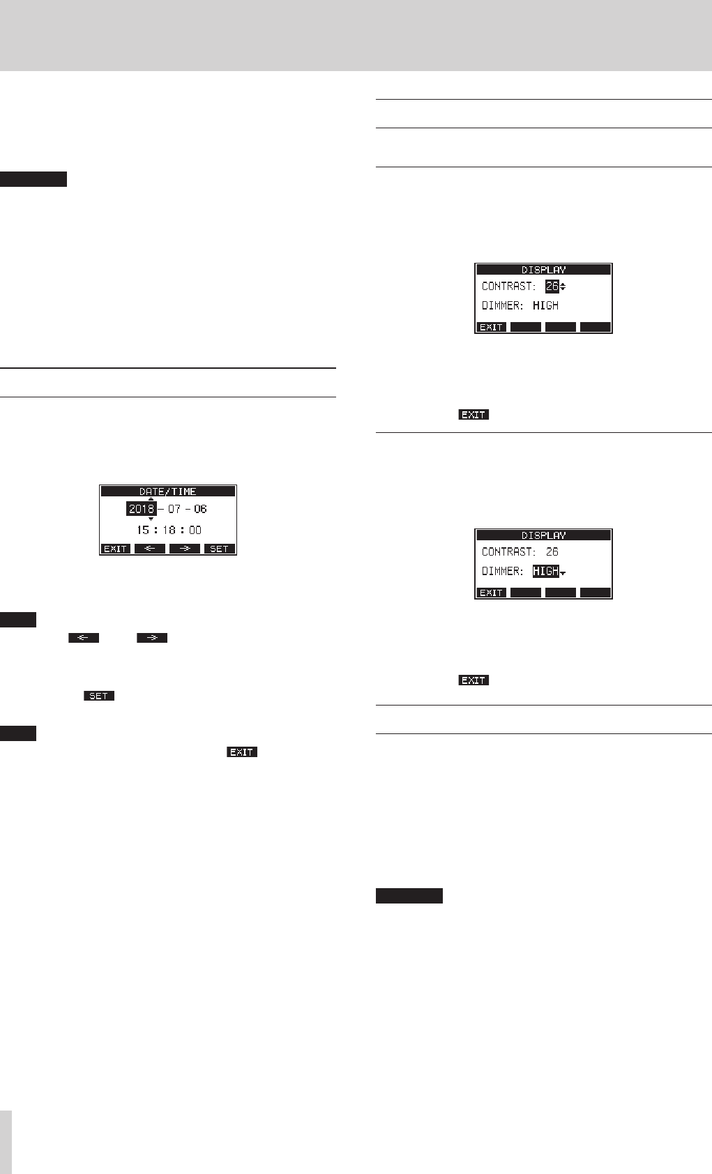
1. On the SYSTEM Screen, select DATE/TIME to open the DATE/TIME
Screen.(see “Menu operation procedures” on page 18)
2. Turn the MULTI JOG dial to change a value, and press the MULTI
JOG dial to confirm it and move the cursor to the next item.
NOTE
Use the F2 and F3 buttons to move the cursor.
3. Change the year, month, day, hour and minute in order, and com-
plete the date and time setting.
4. Press the F4 button to confirm the setting and return to the
SYSTEM Screen.
NOTE
i When making a setting, you can press the F1 button to cancel
the changes and return to the SYSTEM Screen.
i When setting the time, the time display will be stopped.
i By setting the TYPE item to DATE on the SONG NAME Screen, the date
and time set here can be used for song names.(see “Setting the song
name format” on page 34)
Adjusting the display
The display contrast and brightness can be adjusted.
Adjusting the display contrast
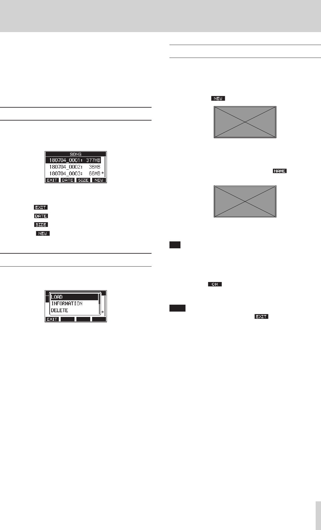
1. On the SYSTEM Screen, select DISPLAY to open the DISPLAY Screen.
(see “Menu operation procedures” on page 18)
2. Select CONTRAST, and press the MULTI JOG dial.
3. Adjust the display contrast.
Options: 10–40 (default: 26)
4. Press the MULTI JOG dial to confirm the setting.
5. Press the F1 button to return to the MENU Screen.
Adjusting the display brightness
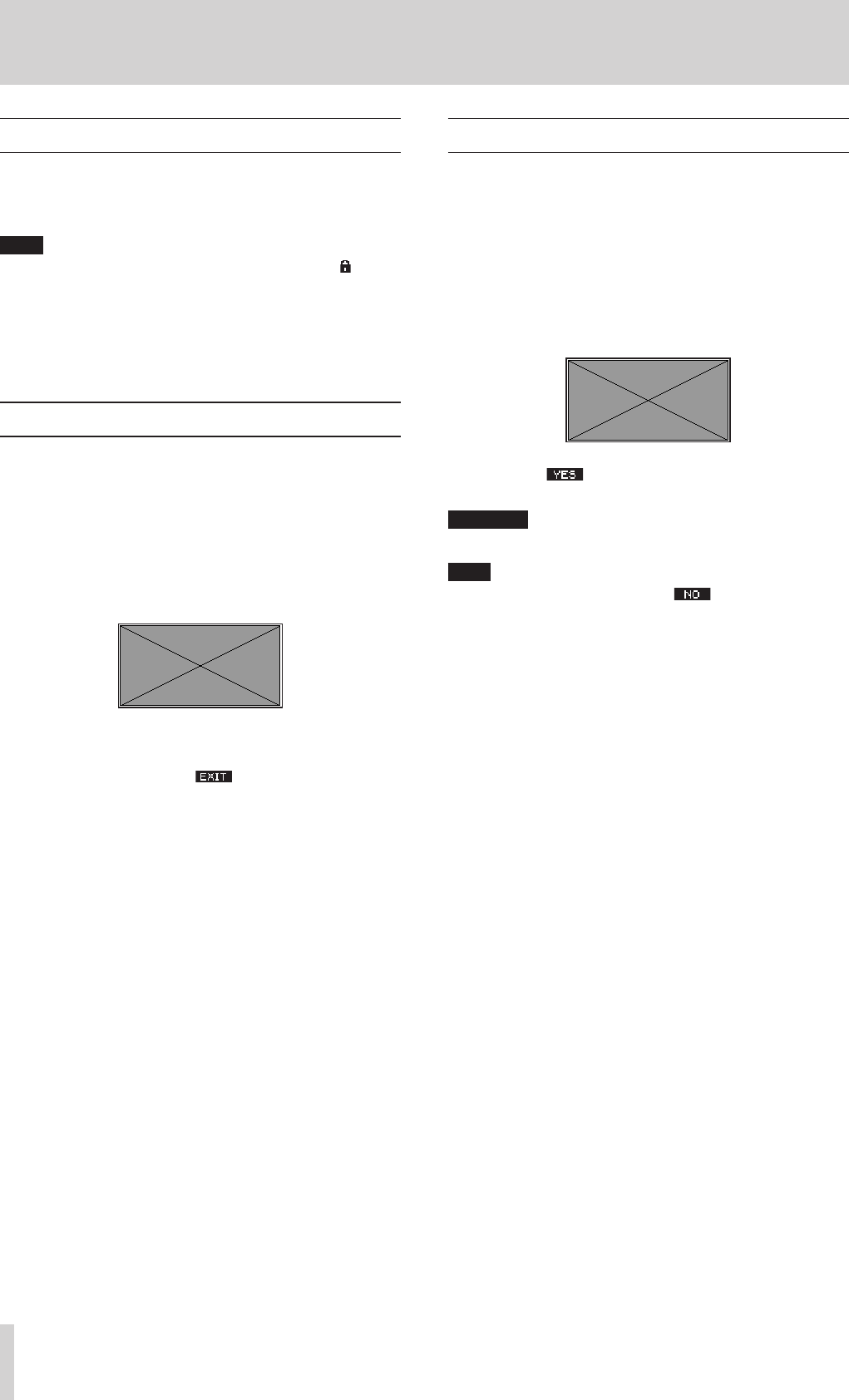
1. On the SYSTEM Screen, select DISPLAY to open the DISPLAY Screen.
(see “Menu operation procedures” on page 18)
2. Select CONTRAST, and press the MULTI JOG dial.
3. Adjust the display brightness.
Options: HIGH (default), LOW
4. Press the MULTI JOG dial to confirm the setting.
5. Press the F1 button to return to the MENU Screen.
Preparing an SD card for use
In order to use an SD card in this unit, this unit must be used to create a
system file on it first.
1. "No sys file Make sys file Are you sure? appears in a pop
up when a new card or a card formatted by another device is
inserted into the unit.
2. Press the MULTI JOG dial to create a system file.
When system file creation is complete, the Home Screen will
reopen.
ATTENTION
In order to record, this unit must be used to format it first.(see “For-
matting SD cards” on page 35)
TASCAM Model 24 23
4 – Managing Songs
This recorder treats each recording data group as one song and man-
ages data by song.
For one song, WAV files are saved for 22 tracks and a stereo master file.
To record or produce music, a song that has already been created needs
to be loaded or a new song needs to be created.
This chapter describes basic operations such as a method for loading
songs and a procedure for creating new songs as well as various func-
tions to mange songs.
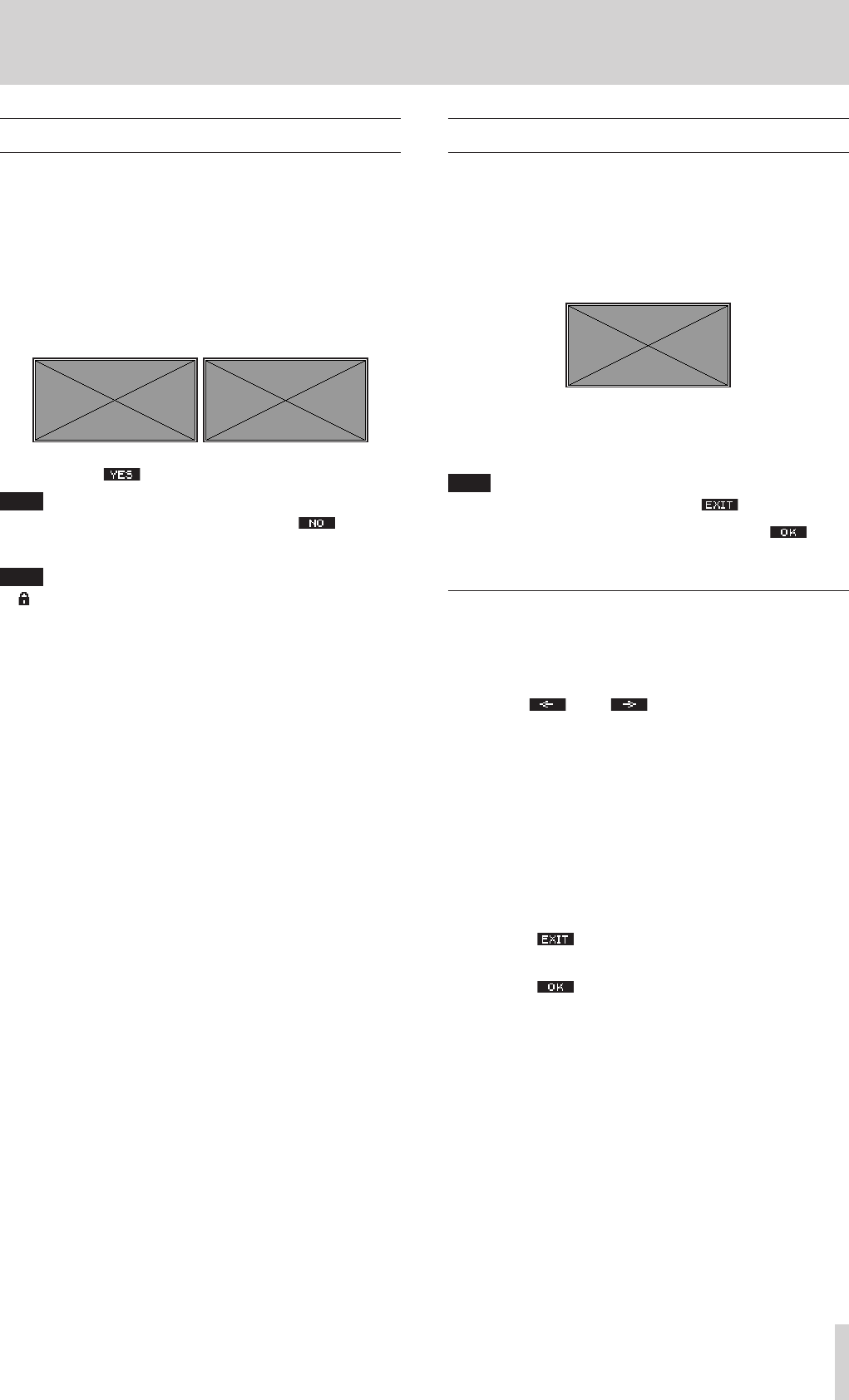
Viewing the song list
To open a list of songs saved on an SD card, select SONG on the MENU
Screen, and press the MULTI JOG dial to open the SONG Screen.(see
“Menu operation procedures” on page 18)
On the SONG Screen, the following functions are assigned to the func-
tion buttons.
0Press the F1 button to return to the MENU Screen.
0Press the F2 button to show the size on the SONG Screen.
0Press the F3 button to show the date on the SONG Screen.
0Press the F4 button to open the NEW Screen where you can
create a new song.(see “Creating a New Song” on page 23)
Song Operation
Select the desired song file on the SONG Screen and press the MULTI
JOG dial to open a pop-up menu list with possible song operations.
To use a song operation, turn the MULTI JOG dial to select the desired
item, and press the MULTI JOG dial.
LOAD
Loads the selected song.
INFORMATION
View information about the selected song.
DELETE
Deletes the selected song.
PROTECT
Protect the selected song.
UNPROTECT
Stop protection of the selected song.
RENAME
Edits the name of the selected song.
Creating a New Song
To record or play with this unit, you must create and load a song.
The following procedure can be used to create a new song.
1. Open the SONG Screen when the recorder is stopped.(see “Menu
operation procedures” on page 18)
2. Press the F4 button to open the NEW Screen.
Created songs are given names (titles) using the characters set on
the SONG NAME Screen followed by a four-digit number.
3. Edit the name of the song as necessary.
To edit the name of the song, press the F2 button to open
the NAME EDIT Screen.
For details about how to edit song names, see “Editing textpage
25.
TIP
The song name can also be edited later using the RENAME Screen.
4. Turn the MULTI JOG dial to select the recording file format.
Options: 44.1kHz - 16bit (default), 44.1kHz - 24bit, 48kHz -
16bit, 44.1kHz - 24bit
5. Press the F4 button to save the currently loaded song and
create a new song.
When song creation completes, the SONG Screen reopens.
NOTE
i To cancel song creation, press the F1 button.
i A maximum of 100 songs can be created on a single SD card.
i Songs are created in the MTR folder on the SD card.
24 TASCAM Model 24
4 – Managing Songs
Loading Songs
Use the following procedure to load the song you want.
1. Open the SONG Screen when the recorder is stopped.(see “Menu
operation procedures” on page 18)
NOTE
The * icon appears for a song currently being loaded. An icon will
appear before protected songs.
2. Select the song that you want to load and press the MULTI JOG
dial to open the menu list pop-up.
3. Select LOAD, and press the MULTI JOG dial.
After the selected song loads, the SONG Screen will reopen.
Viewing song information
You can check the song name (title), sampling frequency, bit rate, size,
date and time.
1. Open the SONG Screen when the recorder is stopped.(see “Menu
operation procedures” on page 18)
2. Select the song with information that you want to check and press
the MULTI JOG dial to open the menu list pop-up.
3. Select INFORMATION, and press the MULTI JOG dial.
The INFORMATION Screen will open.
The song name, sampling frequency, bit rate, size, date and time
will be shown.
4. After checking, press the F1 button to return to the SONG
Screen.
Deleting songs
You can delete songs.
Deleting unnecessary songs when the SD card space is low can create
more open space.
1. Open the SONG Screen when the recorder is stopped.(see “Menu
operation procedures” on page 18)
2. Select the song that you want to delete and press the MULTI JOG
dial to open the menu list pop-up.
3. Select DELETE, and press the MULTI JOG dial.
The SONG DELETE Screen will open.
4. Press the F4 button to confirm deletion.
When song deletion completes, the SONG Screen reopens.
ATTENTION
Deleted songs cannot be restored.
NOTE
i To cancel song deletion, press the F1 button.
i The current song cannot be deleted. To delete the current song, load
another song first.
TASCAM Model 24 25
4 – Managing Songs
Protecting/unprotecting songs
By protecting a song, you can disable editing, recording and deletion
operations for that song.
You can protect and stop protecting songs.
1. Open the SONG Screen when the recorder is stopped.(see “Menu
operation procedures” on page 18)
2. Select the song that you want to protect or unprotect and press the
MULTI JOG dial to open the menu list pop-up.
3. Select PROTECT or UNPROTECT, and press the MULTI JOG dial.
The PROTECT or UNPROTECT screen will open.
4. Pres the F4 button to protect or unprotect the song.
NOTE
To cancel protection or unprotection, press the F1 button.
5. When song protection completes, the SONG Screen reopens.
NOTE
i icons appear before songs that are protected in the song list
shown for copying, deletion and other operations.
i If you try to execute a prohibited operation (editing, recording, dele-
tion) on a protected song, "Song is protected." will appear in a
pop-up message on the display.
Editing song names
1. Open the SONG Screen when the recorder is stopped.(see “Menu
operation procedures” on page 18)
2. Select the song with name that you want to change and press the
MULTI JOG dial to open the menu list pop-up.
3. Select RENAME, and press the MULTI JOG dial.
The RENAME Screen will open.
4. Edit the song name.
For details about how to edit song names, see “Editing textpage
25below.
NOTE
To cancel song name editing, press the F1 button.
5. When finished editing the song name, press the F4 button
to confirm the song name.
When song name editing is complete, the SONG Screen reopens.
Editing text
Use these operations to edit text.
Changing the cursor (editing point) position
Use the F2 and F3 buttons.
You can also press the MULTI JOG dial to move to the next
character.
Deleting the character at the cursor position:
Turn the MULTI JOG dial.
You can input up to 11 characters, including symbols, numbers, and
uppercase and lowercase letters.
Leaving a single space open:
Turn the MULTI JOG dial to select a blank space at the left end of
any row, and press the MULTI JOG dial.
Canceling edits:
Press the F1 button.
Confirming the changes:
Press the F4 button.