TENDA TECHNOLOGY 4G301 Wireless N300 3G/4G Router User Manual Part 2
SHENZHEN TENDA TECHNOLOGY CO., LTD. Wireless N300 3G/4G Router Part 2
Contents
- 1. User Manual Part 1
- 2. User Manual Part 2
User Manual Part 2
III Features & Configurations
41
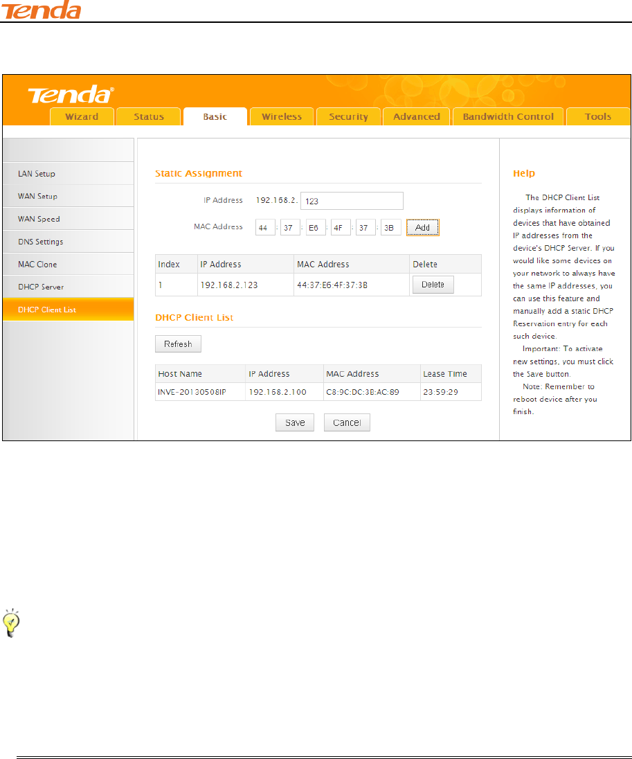
192.168.2.123.
Configuration Procedures:
① Enter the last number of the IP address you want to reserve, for example, 123.
② Enter the MAC address of 44:37:E6:4F:37:3B.
③ Click Add.
④ Click Save to save your settings.
Tip-------------------------------------------------------------------------------------------------------------------------------------------
1. If the IP address you have reserved for your PC is currently used by another client, then you
will not be able to obtain a new IP address from the device's DHCP server, instead, you must
manually specify a different IP address for your PC to access Internet.
2. For PCs that has already obtained IP addresses, you may need to perform the Repair action
to activate the configured static IP addresses.
III Features & Configurations
42
3 Wireless Settings
This section includes the following:
Basic
Security
Access Control
Connection Status
To configure wireless network name, channel and other basic wireless settings, see
Wireless - Basic.
To secure your wireless network, see Wireless Security.
To restrict access to your wireless network, see Access Control.
To see who are connecting to your wireless network, see Connection Status.
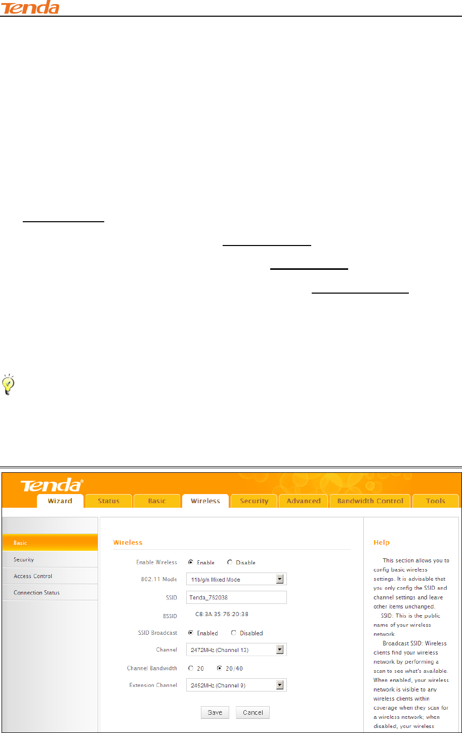
3.1 Wireless-Basic
Here you can configure the basic wireless settings of the router.
Tip--------------------------------------------------------------------------------------------------------------------------------------------
1. The SSID is Tenda_XXXXXX by default, where XXXXXX is the last six characters in the
device's MAC address. You can find it on the label attached on the bottom of the device.
2. If you are not an advanced user, it is advisable to only change the SSID (name of the network)
and channel and leave other items unchanged.

III Features & Configurations
43
Configuration Procedures:
① SSID: This is the public name of your wireless network.
② Channel: Select a channel or select Auto to let system automatically select one for your
wireless network to operate on if you are unsure. The best selection is a channel that is the least
used by neighboring networks.
③ Click Save to save your settings.
Knowledge Center-----------------------------------------------------------------------------------------------
1. Network Mode (802.11 Mode): Select a correct mode according to your wireless clients.
11b: This network mode delivers wireless speed up to 11Mbps and is only compatible
with 11b wireless clients.
11g: This network mode delivers wireless speed up to 54Mbps and is only compatible
with 11g wireless clients.
11b/g mixed: This network mode delivers wireless speed up to 54Mbps and is
compatible with 11b/g wireless clients.
11b/g/n mixed: This network mode delivers wireless speed up to 300Mbps and is
compatible with 11b/g/n wireless clients.
2. BSSID: This is the MAC address of the device's wireless interface.
3. SSID Broadcast: This option allows you to have your network names (SSIDs) publicly
broadcast or if you choose to disable it, the SSIDs will be hidden.
4. Channel Bandwidth: Select a proper channel bandwidth to enhance wireless performance.
This option is available only in 802.11b/g/n. Wireless speed in the channel bandwidth of 20/40 is 2
times in 20.
5. Extension Channel: This is used to ensure N speeds for 802.11n devices on the network. This
option is available only in 11b/g/n mixed mode with channel bandwidth of 20/40.
III Features & Configurations
44
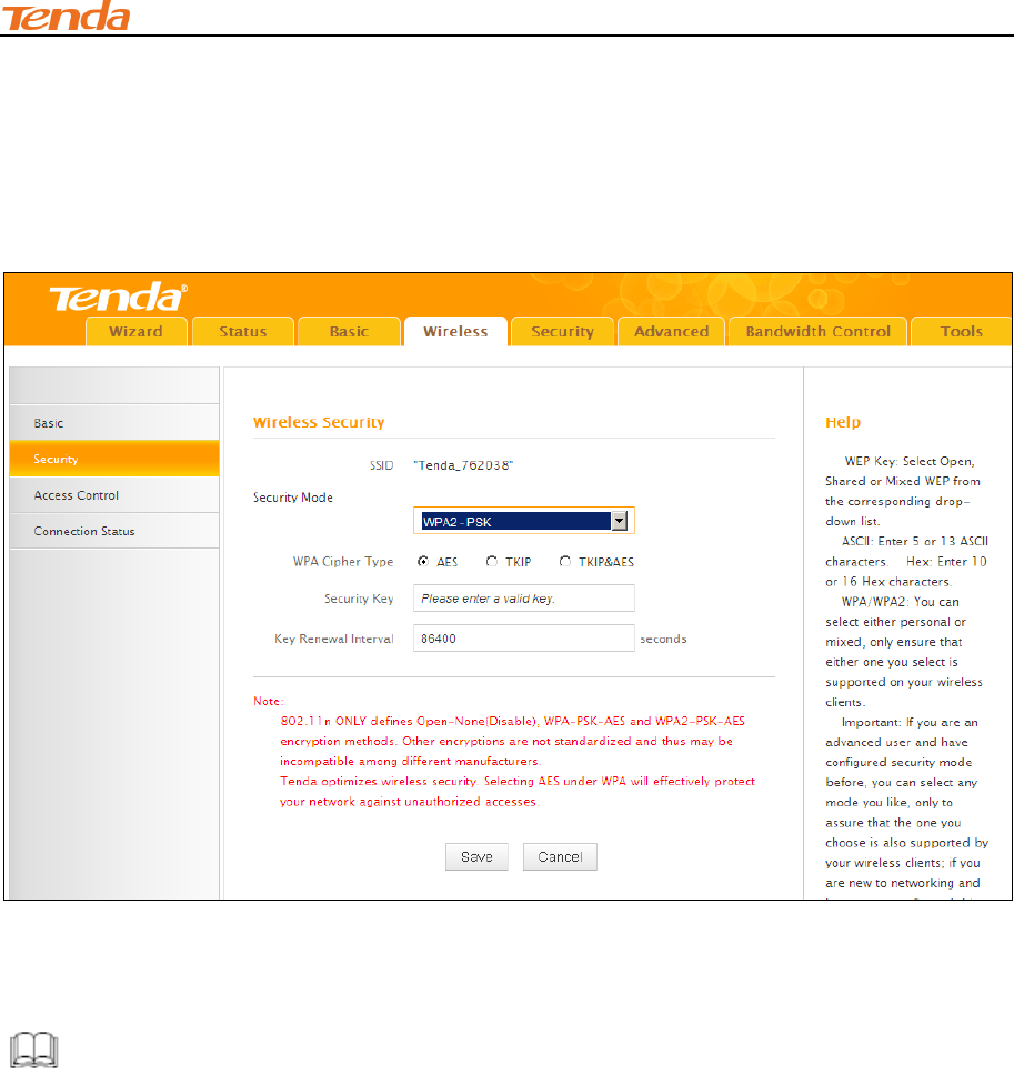
3.2 Wireless Security
Click Wireless -> Security to enter the Security screen. Here you can define a security key to
secure your wireless network against unauthorized accesses.
① Configure security mode, cipher type and security key.
② Click Save to save your settings.
Knowledge Center-----------------------------------------------------------------------------------------------
1. WEP: WEP is intended to provide data confidentiality comparable to that of a traditional wired
network.
2. Open: Wireless speed can reach up to 54Mbps if WEP - Open is selected.
3. Shared: Wireless speed can reach up to 54Mbps if WEP - Shared is selected.
4. Mixed WEP: Compatible with both Open and Shared. Clients can connect to your wireless
network either using Open or Shared
5. Default Key: Select a key to be effective for the current WEP encryption. For example, if you
select Key 2, wireless clients must join your wireless network using this Key 2.
6. WPA-PSK:WPA personal, support AES and TKIP cipher types.
7. WPA2-PSK:WPA2 personal, support AES, TKIP and TKIP+AES cipher types.

III Features & Configurations
45
8. WPA/WPA2-PSK mixed: If selected, both WPA-PSK and WPA2-PSK secured wireless clients
can join your wireless network.
9. AES: If selected, wireless speed can reach up to300Mbps.
10. TKIP: If selected, wireless speed can reach up to 54Mbps.
11.TKIP+AES: If selected, both AES and TKIP secured wireless clients can join your wireless
network.
12. Key Renewal Interval: Enter a valid time period for the key to be changed.
3.3 Access Control
Specify a list of devices to "Permit" or "Forbid" a connection to your wireless network via the
devices’ MAC Addresses. Click Wireless -> Access Control to enter the configuration screen.
There are three options available: Disable, Deny and Allow.
A. If you want to allow all wireless clients to join your wireless network, select
Disable.
B. If you want to allow ONLY the specified wireless clients to join your wireless network, select
Allow.
C. If you want to disallow ONLY the specified wireless clients to join your wireless network, select
Deny.
III Features & Configurations
46
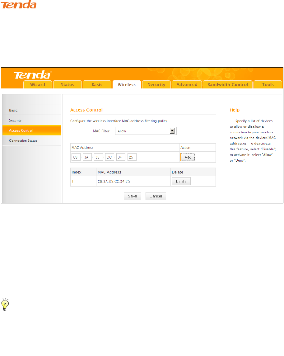
Wireless Access Control Application Example:
To only allow your own notebook at the MAC address of C8:3A:35:CC:34:25 to join your wireless
network
Configuration Procedures:
① Select Allow.
② Enter the MAC address of the wireless device you want to restrict. Here in this example, enter
C8:3A:35:CC:34:25.
③ Click Add to add the MAC address to the MAC address list.
④ Click Save to save your settings.
Tip---------------------------------------------------------------------------------------------------------------------------------------------
Up to 16 wireless MAC addresses can be configured.
1. If you don't want to configure the complex wireless security settings and want to disallow
others to join your wireless network, you can configure a wireless access control rule to allow only
your own wireless device.
III Features & Configurations
47
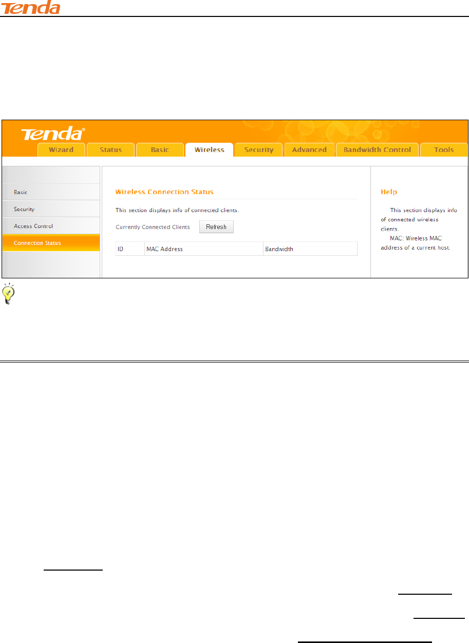
3.4 Connection Status
Click Wireless -> Connection Status. Here you can see a list of wireless devices connected to
the router.
Tip---------------------------------------------------------------------------------------------------------------------------------------------
1. The bandwidth here refers to the channel bandwidth instead of wireless connection rate.
You can know whether there are unauthorized accesses to your wireless network by viewing the
wireless client list.
4 Security
This section includes the following:
Client Filter
MAC Filter
URL Filter
Remote Web Management
To restrict your LAN PCs to access certain services on Internet via their IP addresses,
see Client Filter.
To restrict your LAN PCs to access Internet via their MAC addresses, see MAC Filter.
To restrict your LAN PCs to access certain websites on Internet via URL, see URL Filter.
To enable the remote web management feature, see Remote Web Management.
III Features & Configurations
48
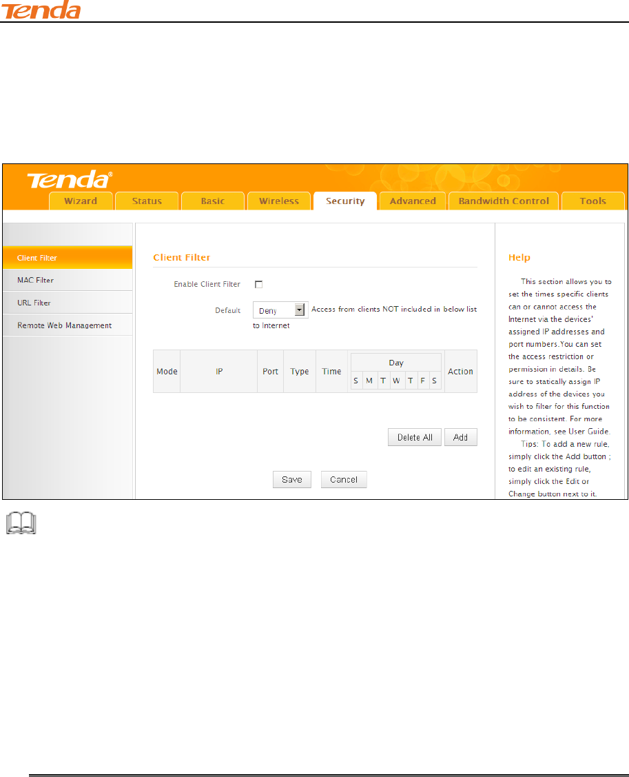
4.1 Client Filter
This section allows you to set the times specific clients can or cannot access the Internet via the
devices’ assigned IP addresses and service port. Click Security to enter the configuration screen.
Knowledge Center-----------------------------------------------------------------------------------------------
1. Default: The default policy for the client filter. For the packets that do not match the set rule, the
default rule is applied.
2. Filter Mode: Specify a filter mode for the rule.
Deny: Disallow the packets that match the set rule to pass the router. For other packets
that do not match the set rule, the default policy is applied.
Allow: Allow the packets that match the set rule to pass the router. For other packets that
do not match the set rule, the default policy is applied.
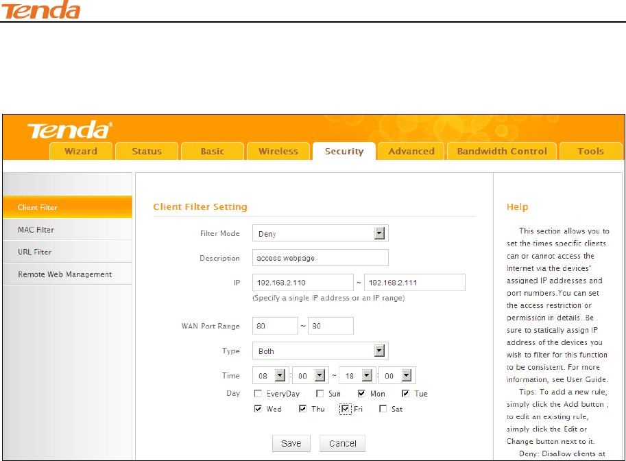
Client Filter Application Example:
To prohibit PCs within the IP address range of 192.168.2.110--192.168.2.111 from accessing web
pages during the time period of 8:00~18:00 from Monday to Friday.
III Features & Configurations
49
Configuration Procedures:
Click Add to add a filter rule.
① Filter Mode: Select Deny.
② Description: Briefly describe the current rule. This field is optional.
③ IP: Enter a starting IP address. Here in this example, enter 192.168.2.110. Enter an ending IP
address. Here in this example, enter 192.168.2.111.
④ WAN Port Range: Enter a service port number. Here in this example, enter 80 (HTTP (port
80) is the standard protocol for web servers.).
⑤ Traffic Type: Select a protocol for the traffic. If you are unsure, select Both.
⑥ Time: Specify a time period for the current rule to take effect. Here in this example, select
8:00~18:00.
Day: Select a day, or several days of the week for the current rule to take effect. Here in this
example, select Mon, Tue, Wed, Thur and Fri.
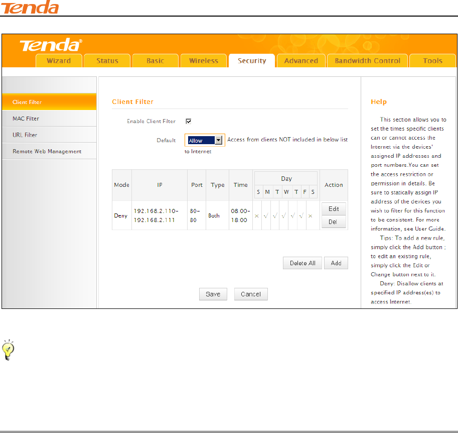
⑦ Click Save to save your settings.
⑧ Enable Client Filter: Check to enable or uncheck to disable the client filter feature.
⑨ Select Allow from the Default drop-down list and then click Save.
III Features & Configurations
50
Tip-------------------------------------------------------------------------------------------------------------------------
1. The valid service port number range is from 1 to 65534.
2. Up to 10 filter rules can be configured.
3. If you have not set up the system time for this device, click Tools -> Time & Date to set up
correct time and date for the rules to be effective.
III Features & Configurations
51
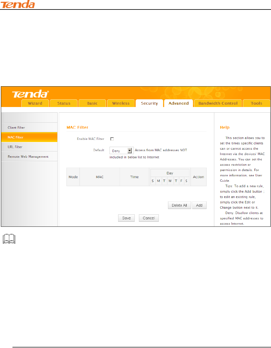
4.2 MAC Filter
This section allows you to restrict specific clients to access the Internet via the devices’ MAC
addresses. Each PC has at least an installed network adapter with a unique MAC address. Click
Security -> MAC Filter to enter the configuration screen.
Knowledge Center ----------------------------------------------------------------------------------------------
1. Default: The default policy for the URL filter. For the packets that do not match the set rule, the
default rule is applied.
2. Filter Mode: Specify a filter mode for the rule.
Deny: Disallow the packets that match the set rule to pass the router. For other packets
that do not match the set rule, the default policy is applied.
Allow: Allow only the packets that match the set rule to pass the router. For other packets
that do not match the set rule, the default rule is applied.
MAC Filter Application Example:
Your router functions as an active DHCP server and delivers an unsecured wireless network. From
time to time, you suffer from slow network speed and start to suspect unauthorized accesses to
your network. You can set MAC filter rules to allow only your PC at 00:E4:A5:44:35:69 and your
wireless device at 00:E4:A5:44:35:6A to access Internet via this router.
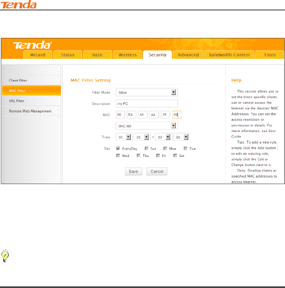
Configuration Procedures:
III Features & Configurations
52
① Click Add to add a filter rule.
② Filter Mode: Select Allow.
③ Description: Briefly describe the current rule. This field is optional.
④ MAC Address: Specify the MAC address of the computer that you want to restrict,
00:E4:A5:44:35:69.
Tip--------------------------------------------------------------------------------------------------------------------------------------------
If the device already connects to your router, you can simply select its MAC address from the MAC
address list drop-down list.
⑤ Time: Use the default settings. When Time is set to 0:00 to 0:00, the rule will be applied 24
hrs/day.
⑥ Day: Select a day, or several days of the week for the current rule to take effect. Here in this
example, select Everyday.
⑦ Click Save to save your settings.
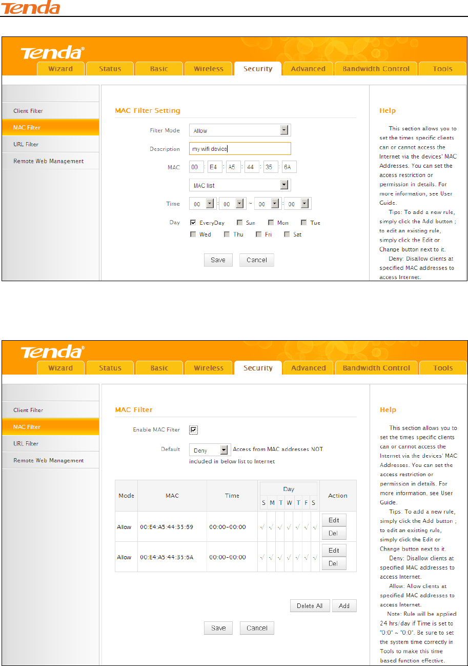
⑧ Repeat steps 1-7 to configure a rule for the MAC address "00:E4:A5:44:35:6A".
III Features & Configurations
53
⑨ Enable MAC Filter: Check to enable or uncheck to disable the MAC filter feature.
⑩ Select Deny from the Default drop-down list and then click Save.
III Features & Configurations
54
Tip--------------------------------------------------------------------------------------------------------------------------------------------
1. Up to 10 MAC filter rules can be configured.
2. If you have not set up the system time for this device, click Tools -> Time & Date to set up
correct time and date for the rules to be effective.
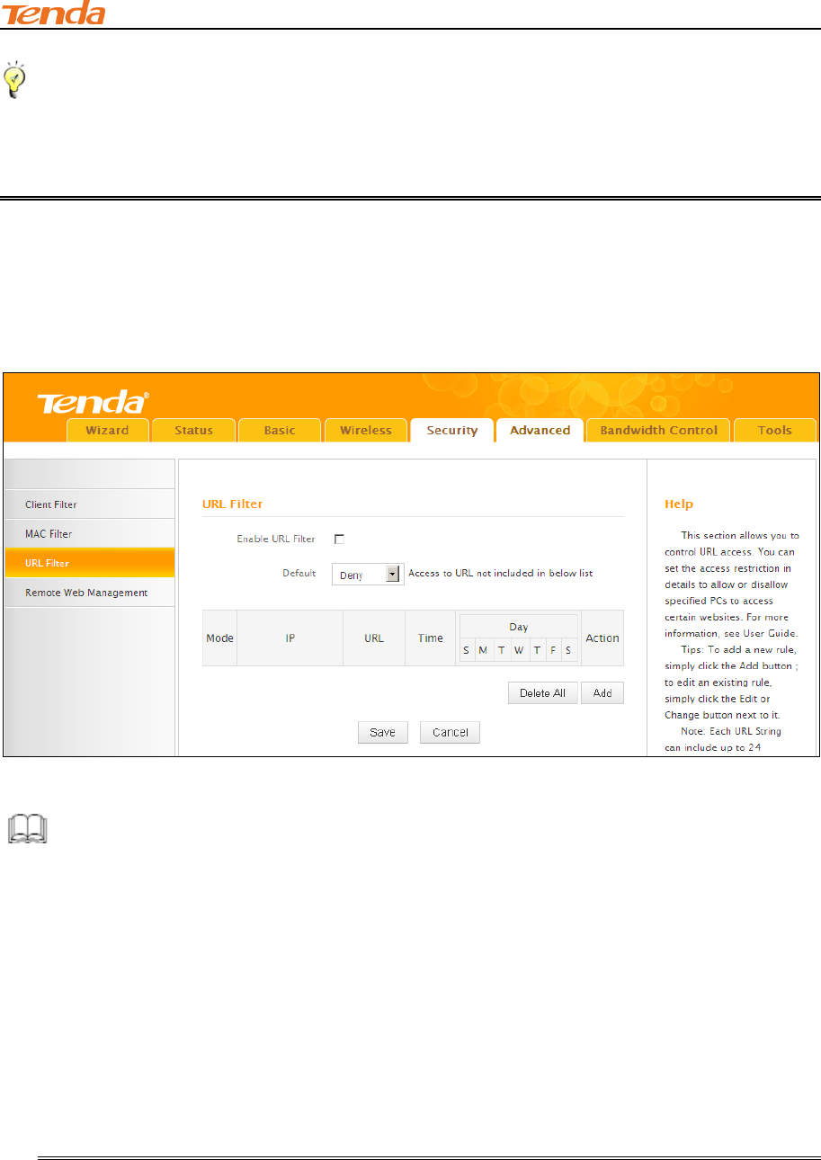
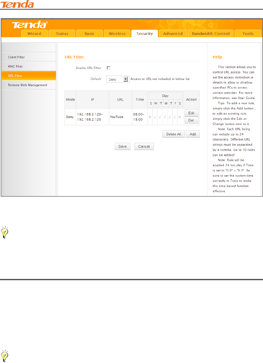
4.3 URL Filter
This section allows you to control URL access. Click Security -> URL Filter to enter the
configuration screen.
Knowledge Cente------------------------------------------------------------------------------------------------
1. Default: The default policy for the URL filter. For the packets that do not match the set rule, the
default rule is applied.
2. Filter Mode: Specify a filter mode for the rule.
Deny: Disallow the packets that match the set rule to pass the router. For other packets
that do not match the set rule, the default policy is applied.
Allow: Allow only the packets that match the set rule to pass the router. For other packets
that do not match the set rule, the default rule is applied.
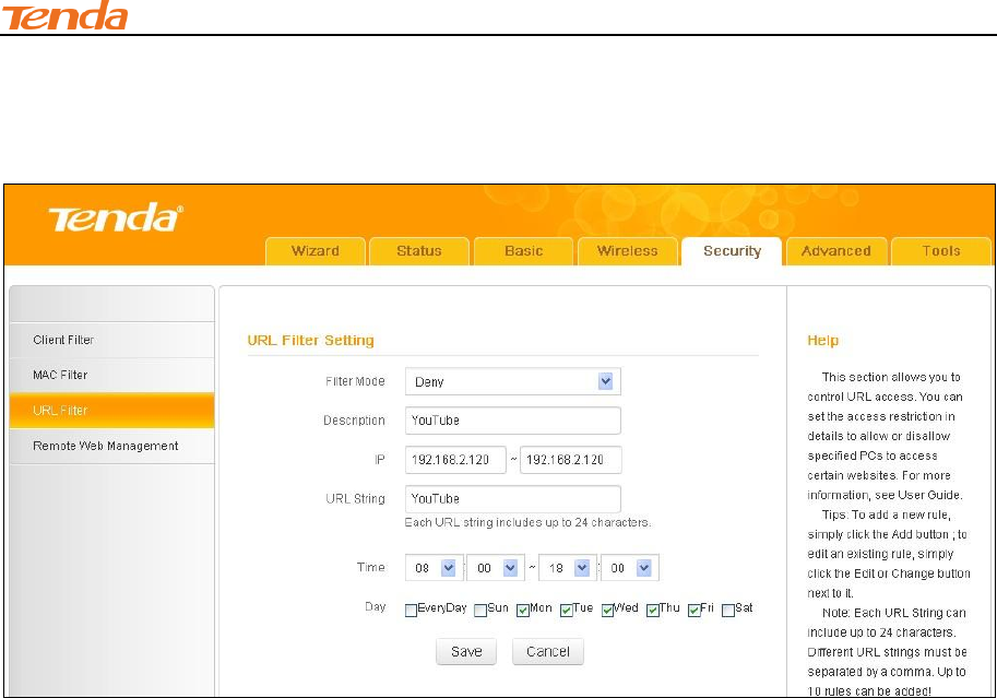
URL Filter Application Example:
To prevent your home PC (192.168.2.120) from accessing “YouTube” from 8:00 to 18:00 during
working days: Monday- Friday.
III Features & Configurations
55
Configuration Procedures:
① Click Add to add a filter rule.
② Filter Mode: Select a filter mode. Here in this example, select Deny.
③ Description: Briefly describe the current rule. This field is optional.
④ IP Address: Enter the IP address you wish to restrict. Here in this example, enter
"192.168.2.120".
⑤ URL String: Enter part of or the entire domain name of the web site you wish to restrict.
Separate different domain names or domain name key words with a comma, for example,
"YouTube, Hollywood.com".
⑥ Time: Specify a time period for the current rule to take effect. Here in this example, select
8:00~18:00.
Day: Select a day, or several days of the week for the current rule to take effect. Here in this
example, select Mon, Tue, Wed, Thur and Fri.
⑦ Click Save to save your settings.
III Features & Configurations
56
⑧ Enable URL Filter: Check to enable or uncheck to disable the URL filter feature.
⑨ Select Allow from the Default drop-down list and then click Save.
Tip---------------------------------------------------------------------------------------------------------------------------------------------
1.Different URL strings must be separated with a comma. To match all websites, use * (asterisk).
2. Up to 10 filter rules can be configured.
3. If you have not set up the system time for this device, click Tools -> Time & Date to set up
correct time and date for the rules to be effective.
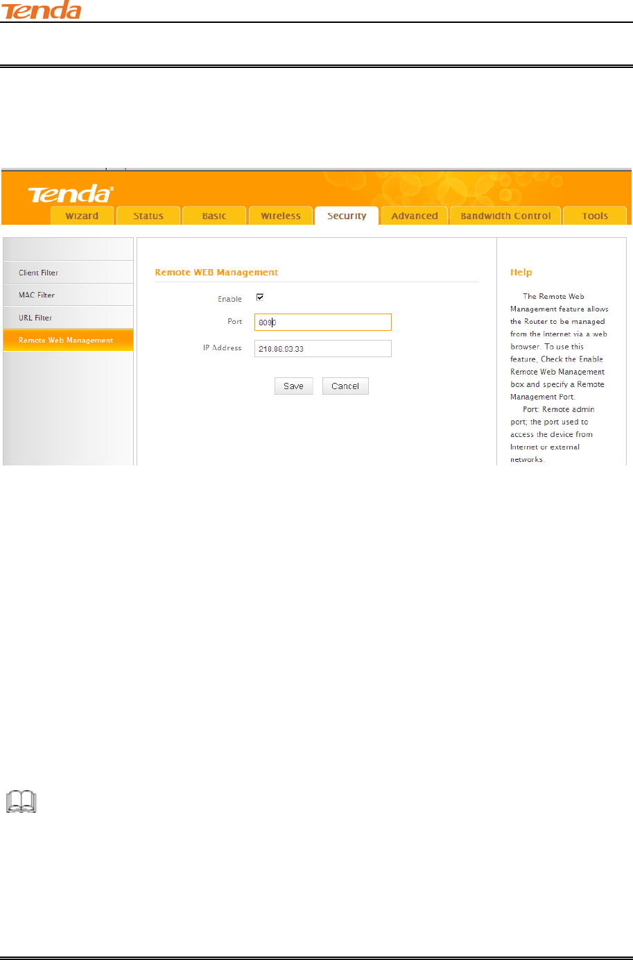
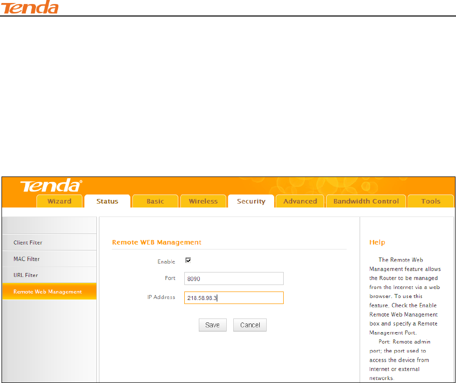
4.4 Remote Web Management
The Remote management allows the device to be configured and managed remotely from the
Internet via a web browser. Click Security -> Remote Web Management to enter the
configuration screen.
Tip------------------------------------------------------------------------------------------------------------------------------------------
1. For better security, configure a port number (between 1025-65535) as remote web
management interface, do not use the number of any common service port (1-1024).
2. Make sure your WAN IP address (Internet IP address) is a public IP address. Private IP
addresses are not routed on the Internet.
3. It is unsafe to make your router remotely accessible to all PCs on external network. For better
III Features & Configurations
57
security, we suggest that only enter the IP address of the PC for remote management.
Remote Web Management Application Example:
To access your router (WAN IP address: 102.33.66.88) at your home from the PC (218.88.93.33)
at your office via the port number 8090
Configuration Procedures:
① Enable: Check to enable the remote Web management feature.
② Port: This is the management port to be open to outside access. Here in this example, enter
8090.
③ IP Address: Specify the IP address for remote management. Here in this example, enter
"218.88.93.33".
④ Click Save to save your settings.
Type "http://102.33.66.88:8090" into your browser’s address or location field and you can access
the router at your home remotely.
Knowledge Center-----------------------------------------------------------------------------------------------
1. IP Address: Here you can specify the IP address for remote management (When set to 0.0.0.0,
the device becomes remotely accessible to all the PCs on Internet or other external networks).
2. Port: This is the management port to be open to outside access. The default setting is 8080.
This can be changed.

III Features & Configurations
58
5 Advanced Applications
This section includes the following:
DDNS
Port Forwarding
DMZ Host
UPnP
Routing Table
To remotely access the device via a domain name or access a server on a LAN PC, see
DDNS .
To let an Internet user access a server on your LAN PC, see Port Forwarding.
To let an Internet user access your LAN PC without any restriction, see DMZ Host.
To automatically map the ports between WAN and LAN, see UPnP.
To view routes, see Routing Table.
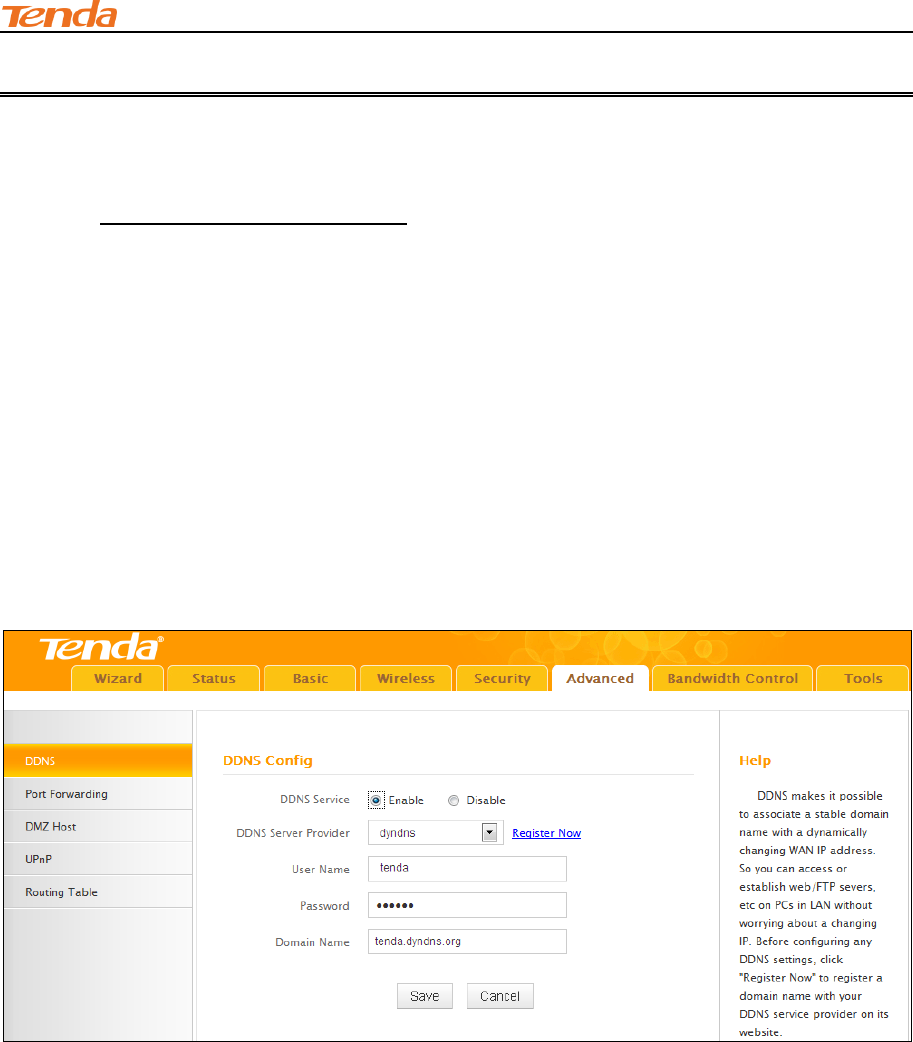
5.1 DDNS
Dynamic DNS or DDNS is a term used for the updating in real time of Internet Domain Name
System (DNS) name servers. We use a numeric IP address allocated by Internet Service Provider
(ISP) to connect to Internet; the address may either be stable ("static"), or may change from one
session on the Internet to the next ("dynamic"). However, a numeric address is inconvenient to
remember; an address which changes unpredictably makes connection impossible. The DDNS
provider allocates a static host name to the user; whenever the user is allocated a new IP address
this is communicated to the DDNS provider by software running on a computer or network device
at that address; the provider distributes the association between the host name and the address to
the Internet's DNS servers so that they may resolve DNS queries. Thus, uninterrupted access to
devices and services whose numeric IP address may change is maintained. Click Advanced ->
DDNS to enter the DDNS screen.
Tip---------------------------------------------------------------------------------------------------------------------------------------------
1. To use the DDNS feature, you need to have an account with one of the Service Providers in the
drop-down menu first.
III Features & Configurations
59
2. This router supports five DDNS service providers: dyndns and no-ip.
DDNS Application Example:
If your ISP gave you a dynamic (changing) public IP address, you want to access your router
remotely (6.5 Remote Web Management) but you cannot predict what your router's WAN IP
address will be, and the address can change frequently. In this case, you can use a commercial
Dynamic DNS service. It lets you register your domain to their IP address and forwards traffic
directed at your domain to your frequently changing IP address.
If you obtain the following account from your dyndns.org service provider:
User Name: tenda
Password: 123456
Domain Name: tenda.dyndns.org.
You want to use the PC at 218.58.98.3 to remotely access this router on port number 8090.
Configuration Procedures:
① DDNS Service: Select Enable.
② Service Provider: Select your DDNS service provider from the drop-down menu. Here in this
example, select dyndns.
③ User Name: Enter the DDNS user name registered with your DDNS service provider. Here in
this example, enter tenda.
④ Password: Enter the DDNS Password registered with your DDNS service provider. Here in
this example, enter 123456.
III Features & Configurations
60
⑤ Domain Name: Enter the DDNS domain name with your DDNS service provider. Here in this
example, enter tenda.dyndns.org.
⑥ Click Save to save your settings.
⑦ Click Security -> Remote Web Management, enable the Remote Web Management feature,
enter 8090 in the Port field, 218.58.98.3 in the IP Address field and then click Save to save your
settings.
When the Connection Status on this DDNS page displays Connected, you can access your
router from the Internet by typing your router’s domain name into your browser’s address or
location field on your PC (218.58.98.3) followed by a colon (:) and the remote management port
number. Here in this example, enter http://tenda.dyndns.org:8090.
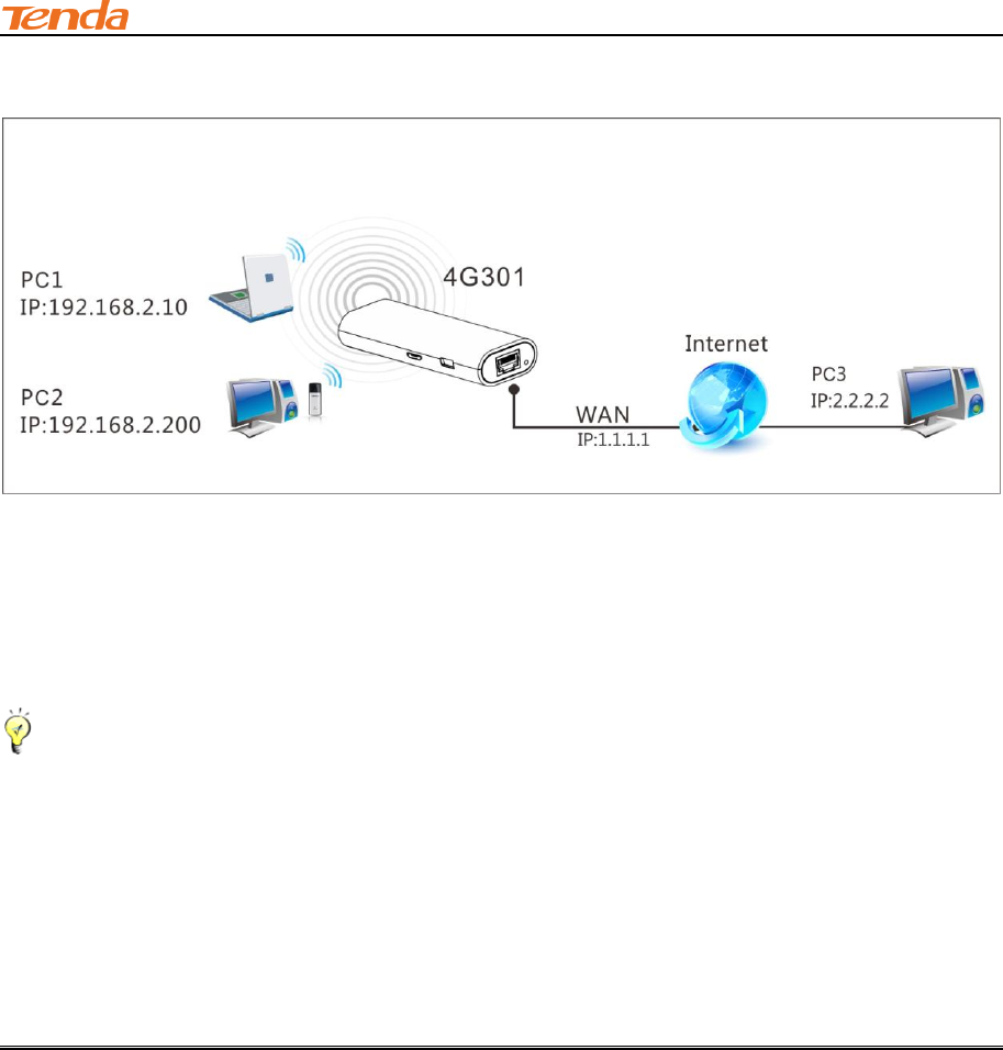
5.2 Port Forwarding
You want to share resources on your PC with your friends who are not in your LAN. But, by default,
the router's firewall blocks inbound traffic from the Internet to your computers except replies to
your outbound traffic. You can use the Port Forwarding feature to create exceptions to this rule so
that your friends can access these files from external networks.
When accessing your PC from Internet, type "protocol://xxx.xxx.xxx.xxx:port number" into your
browser’s address or location field. The protocol and port are the ones used by the service and
"xxx.xxx.xxx.xxx" is the WAN IP address of your router. For example, a FTP server uses the ftp
protocol and 21 (standard port number).
III Features & Configurations
61
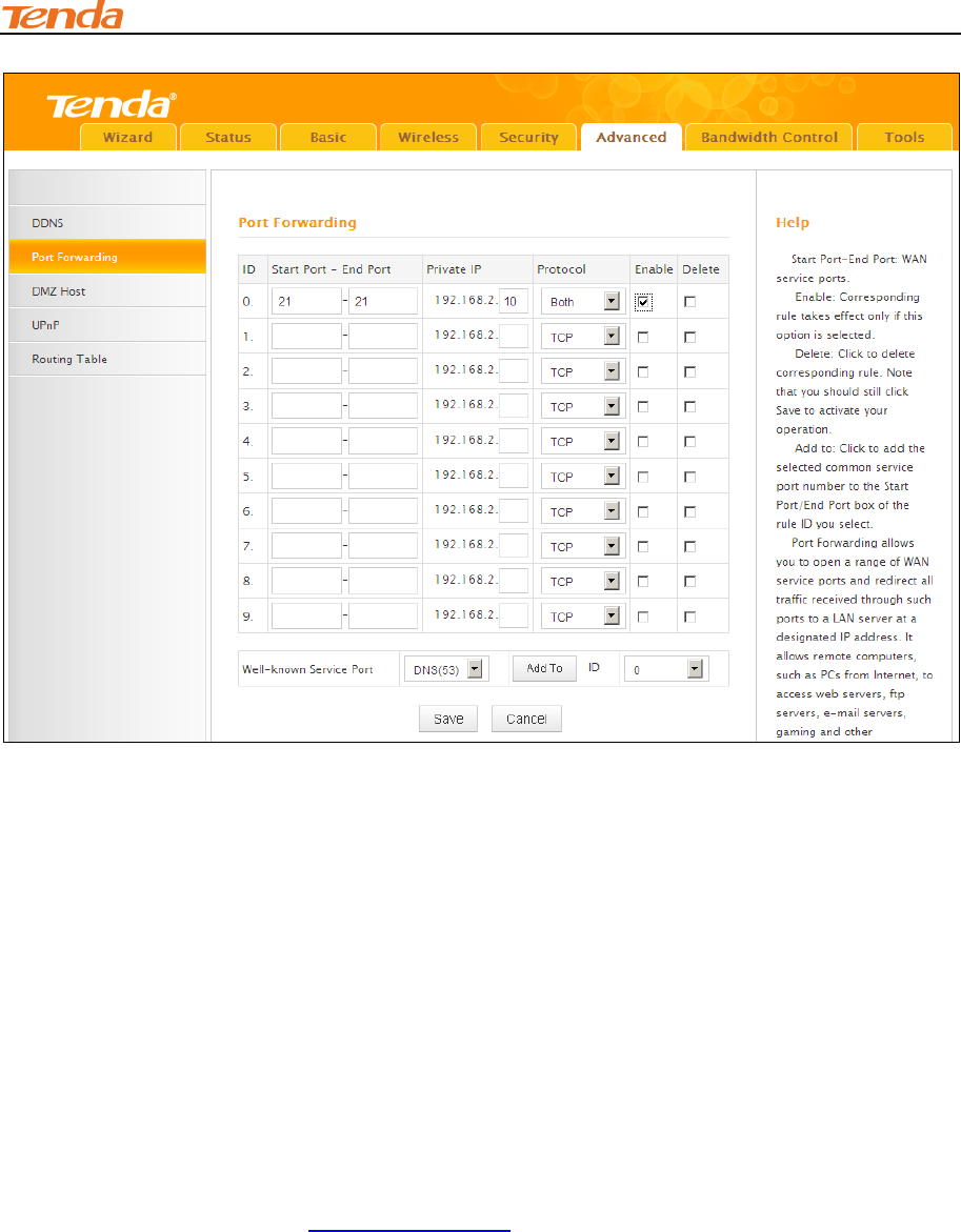
Click Advanced -> Port Forwarding to enter the configuration screen.
Application Example:
As shown in the figure above, your PC at 192.168.0.10 connects to the router and runs a FTP
server on port number 21. Your friends want to access this FTP server on your PC from external
network.
Tip--------------------------------------------------------------------------------------------------------------------------------------------
To successfully implement the port forwarding feature, note below:
1. Make sure your WAN IP address (Internet IP address) is a public IP address. Private IP
addresses are not routed on the Internet.
2. Make sure you enter correct service port numbers.
3. To ensure that your server computer always has the same IP address, assign a static IP
address to your PC.
4. Operating System built-in firewall and some anti-virus programs may block other PCs from
accessing resources on your PC. So it is advisable to disable them before using this feature.
III Features & Configurations
62
Configuration Procedures:
① Start Port: Enter the starting port number for the service. Here in this example, enter 21.
End Port: Enter the ending port number for the service. Here in this example, enter 21.
② Internal IP: Enter the IP address of your local computer that will provide this service. Here in
this example, enter 192.168.2.10.
③ Protocol: Specify the protocol required for the service utilizing the port(s).
④ Check Enable to activate this rule.
⑤ Click Save to save your settings.
If your WAN IP address is 202.33.56.88, when accessing your FTP server from external network,
your friends only need to enter ftp://202.33.56.88:21 in their browsers.
III Features & Configurations
63
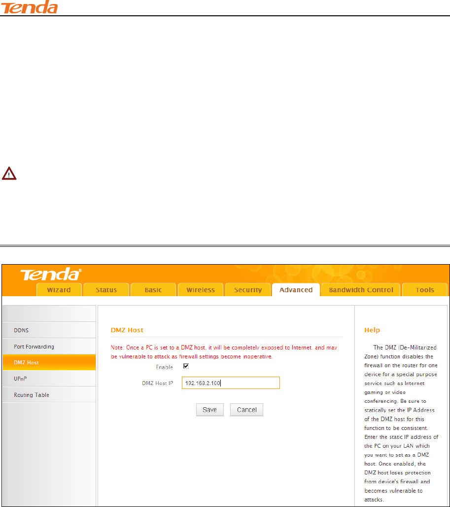
5.3 DMZ Host
The DMZ (De-Militarized Zone) function disables the firewall on the router for one device for a
special purpose service such as Internet gaming or video conferencing applications that are not
compatible with NAT (Network Address Translation). Click Advanced -> DMZ Host to enter the
DMZ Host screen.
Note ---------------------------------------------------------------------------------------------------------------------
1. DMZ host poses a security risk. A computer configured as the DMZ host loses much of the
protection of the firewall and becomes vulnerable to attacks from external networks.
2. Hackers may use the DMZ host computer to attack other computers on your network.
Configuration Procedures:
① DMZ Host IP Address: The IP Address of the device for which the router’s firewall will be
disabled. Be sure to statically set the IP Address of that device for this function to be consistent.
② Enable: Check to enable the DMZ host.
③ Click Save to save your settings.
III Features & Configurations
64
Tip---------------------------------------------------------------------------------------------------------------------------------------------
1. Be sure to statically set the IP Address of the computer that serves as a DMZ host for this
function to be consistent.
2. Security softwares such as anti-virus software and OS built-in firewall, etc may affect the DMZ
host feature. Disable them if DMZ host fails.
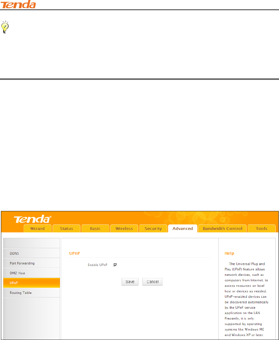
5.4 UPNP
The Universal Plug and Play (UPnP) feature allows network devices, such as computers from
Internet, to access resources on local host or devices as needed. UPnP-enabled devices can be
discovered automatically by the UPnP service application on the LAN. If you use applications such
as multiplayer gaming, peer-to-peer connections, real-time communications such as instant
messaging, or remote assistance (a feature in Windows XP), you may need to enable Universal
Plug and Play (UPnP) for better experience.
Click Advanced -> UPnP to enter the UPnP screen. The UPnP feature is enabled by default.
III Features & Configurations
65
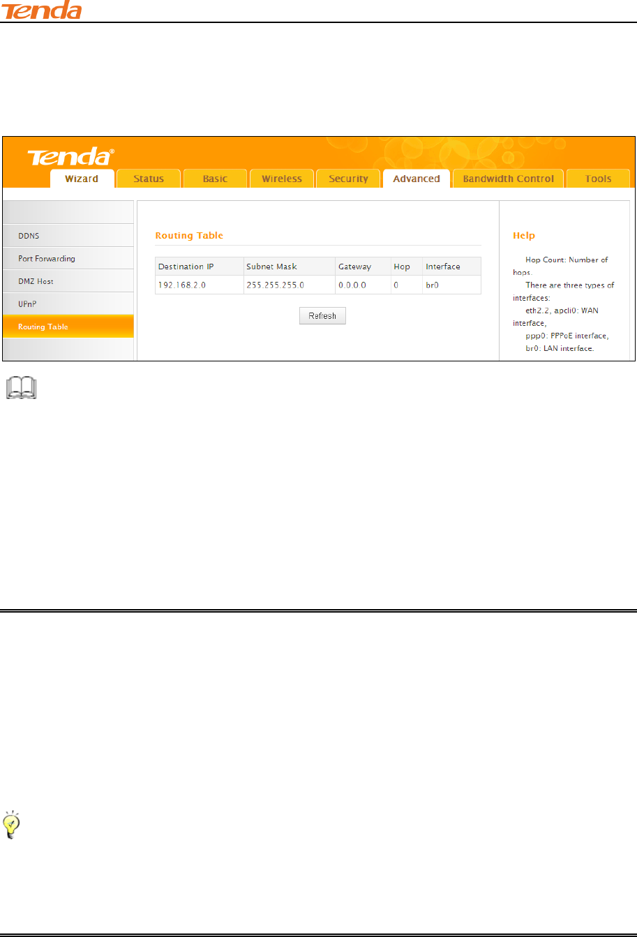
5.5 Route Table
Click Advanced -> Route Table to view the router's route table.
Knowledge Center ----------------------------------------------------------------------------------------------
1. Destination IP: The IP address of the final destination. "0.0.0.0" indicates any network
segment.
2. Subnet Mask: The subnet mask for the specified destination.
3. Gateway: This is the next router on the same LAN segment as the router to reach.
4. Hop: This stands for the number of routers between your network and the destination.
5. Interface: The interface between your router and the final destination.
6 Bandwidth Control
If there are multiple PCs behind your router competing for limited bandwidth resource, then you
can use this feature to specify a reasonable amount of bandwidth for each such PC, so that no one
will be over stuffed or starved to death. Click Bandwidth Control to enter the configuration
interface.
Tip--------------------------------------------------------------------------------------------------------------------------------------------
1. 1M=128KByte/s.
2. The volume of uplink traffic/downlink traffic should not be larger than that allowed on your
router's WAN (Internet) port. You can ask your ISP to provide the volume of Internet traffic.
3. The bandwidth for ADSL/DSL line usually refers to the download bandwidth.
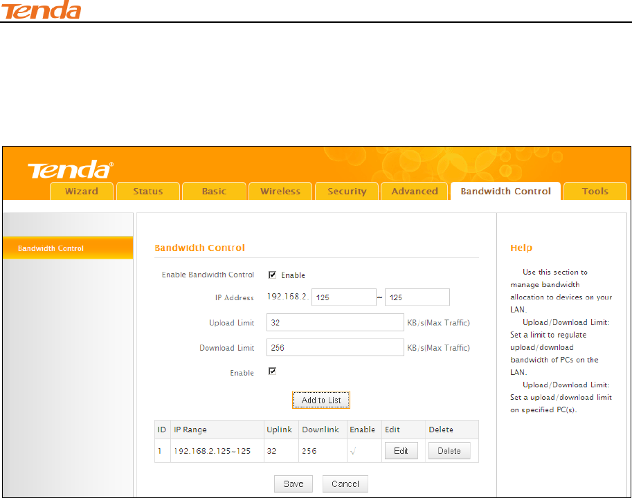
Bandwidth Control Application Example:
You share a 4M-broadband service with your neighbor (at 192.168.2.125). He always downloads a
III Features & Configurations
66
large volume of data from Internet, which sharply frustrates your Internet surfing experience; you
can use this feature to set limits for the volume of Internet traffic he can get. For example, you can
split the 4M into two, so your neighbor can only use up to 2M Internet traffic and you can enjoy 2M.
Configuration Procedures:
① Enable Bandwidth Control: Check the Enable box to enable the Bandwidth Control feature.
② IP Address: Enter the last number of the IP address. Here in this example, enter 125 in both
boxes.
③ Upload Limit: Set a limit to regulate upload bandwidth of PCs on the LAN. Here in this example,
enter 32 in both boxes.
④ Download Limit: Set a limit to regulate download bandwidth of PCs on the LAN. Here in this
example, enter 256 in both boxes.
⑤ Enable: Check to enable the current rule.
⑥ Add to List: Click to add current rule to the rule list.
⑦ Click Save to save your settings.

III Features & Configurations
67
7 Tools
This section explains the following:
Time & Date
Firmware Upgrade
Backup & Restore
Restore Factory Default
Change Password
Logs
Reboot
To configure system time, see Time & Date.
To upgrade firmware, see Firmware Upgrade.
To backup or restore configurations, see Backup & Restore.
To restore factory default settings, see Restore to Factory Default Settings.
To change login password, see Change Password.
To view system and WAN logs, see Logs.
To restart device, see Reboot.
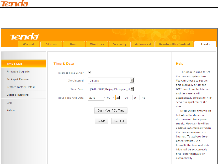
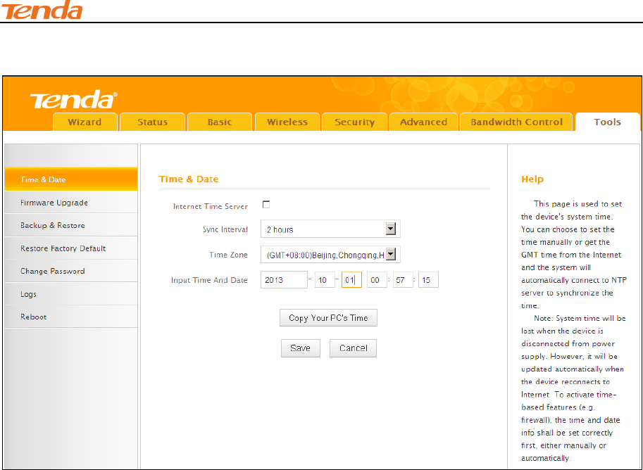
7.1 Time& Date
Click Tools -> Time & Date to enter the time screen.
Tip------------------------------------------------------------------------------------------------------------------------------------------
Configured time and date info will be lost if the device gets disconnected from power supply.
However, it will be updated automatically when the device reconnects to Internet. To activate
time-based features (e.g. firewall), the time and date info shall be set correctly first, either
manually or automatically.
III Features & Configurations
68
A. Sync with Internet time servers
Configuration Procedures:
① nternet Time Server: If enabled, time and date will be updated automatically from
the Internet. Check to enable the feature.
② Sync Interval: Specify a time interval for periodic update of time and date
information from the Internet.
③ Time Zone: Select your current time zone.
④ Click Save to save your settings.
III Features & Configurations
69
B. Set Time and Date Manually/Sync with Your PC
Configuration Procedures:
① Internet Time Server: If enabled, time and date will be updated automatically from the
Internet. Uncheck to disable the feature.
② Specify the time and date manually or click the Copy Your PC's Time to automatically copy
your PC's time to the device.
③ Click Save to save your settings.
And then go to Status to make sure the system time is correctly updated.
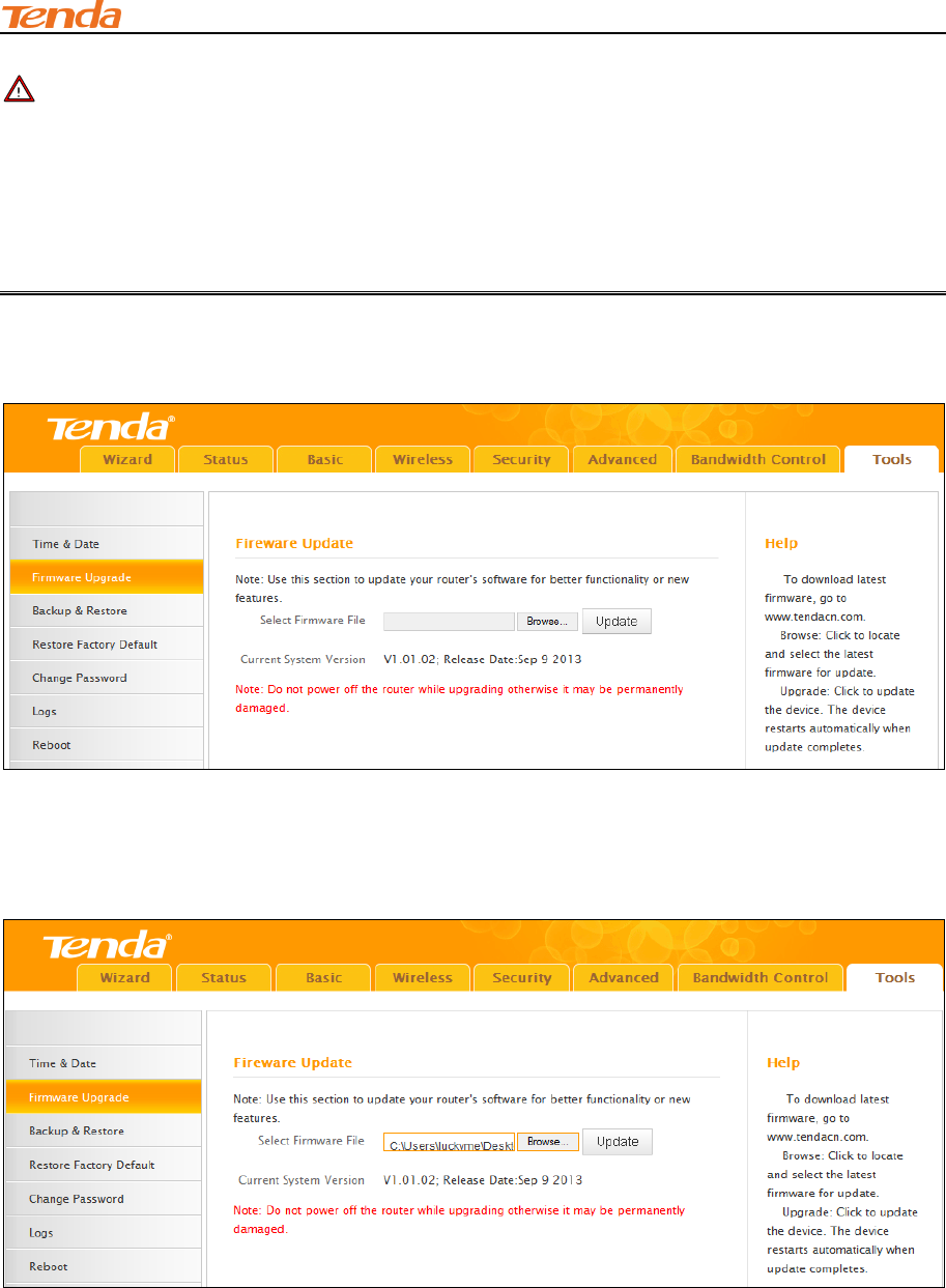
7.2 Firmware Upgrade
Click Tools -> Firmware Upgrade to enter the configuration screen. Firmware upgrade is
released periodically to improve the functionality of your device and also to add new features. If
you run into a problem with a specific feature of the device, log on to our website
(www.tendacn.com) to download the latest firmware to update your device. If you run into a
problem with a specific feature of the device, log on to our website (www.tendacn.com) to
download the latest firmware to update your device.
III Features & Configurations
70
Note ----------------------------------------------------------------------------------------------------------------------
1. Before you upgrade the firmware, make sure you are having a correct firmware. A wrong
firmware may damage the device.
2. It is advisable that you upgrade the device's firmware over a wired connection. DO NOT
interrupt the power to the router when the upgrade is in process otherwise the router may be
permanently damaged.
Configuration Procedures:
① Click Browse.
② Select the upgrade file and click Open.
③ Click Update.
④ Click OK on the appearing screen and wait for it to complete.
When upgrade is completed, view Current System Version. It should display the firmware you
load.
III Features & Configurations
71
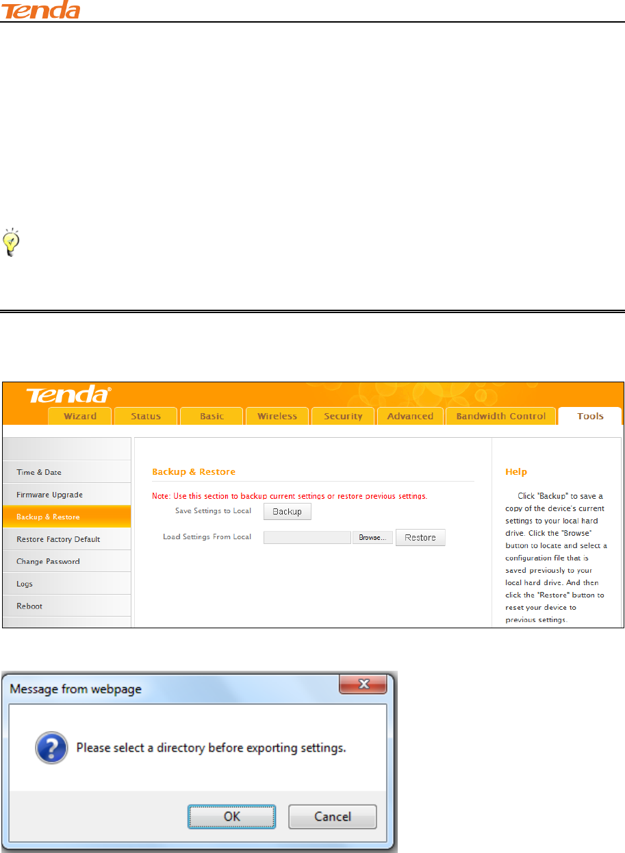
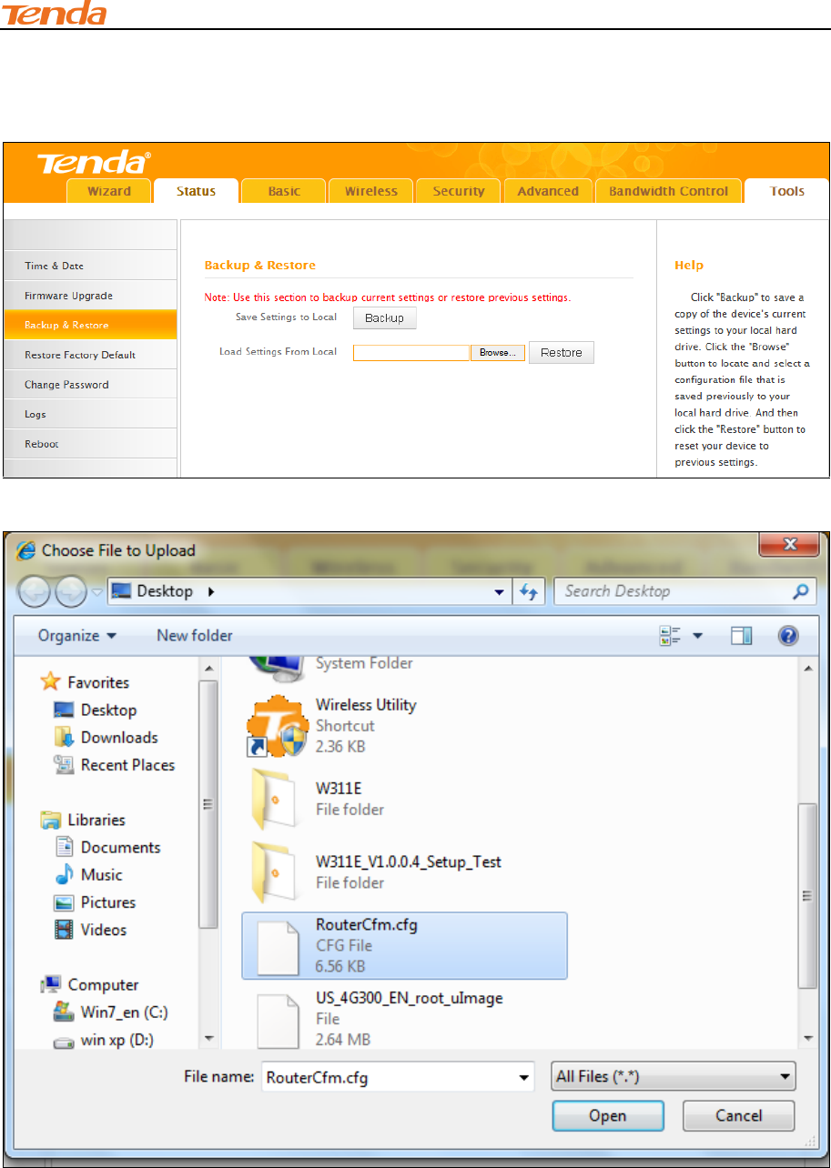
7.3 Backup & Restore
Once you have configured the device the way you want it, you can save these settings to a
configuration file on your local hard drive that can later be imported to your device in case that the
device is restored to factory default settings. Click Tools -> Back & Restore to enter the
configuration screen.
Tip--------------------------------------------------------------------------------------------------------------------------------------------
The default configuration file name is "RouterCfm.cfg". Do include the file name suffix of ".cfg"
when renaming the file name to avoid problems.
Backup Configuration Procedures:
① Click Backup.
② Click OK on the appearing window.
III Features & Configurations
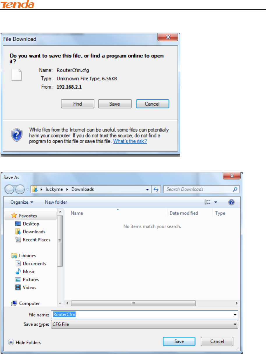
72
③ Click Save on the File Download window.
④ Select a local hard drive to save the file and click Save.
III Features & Configurations
73
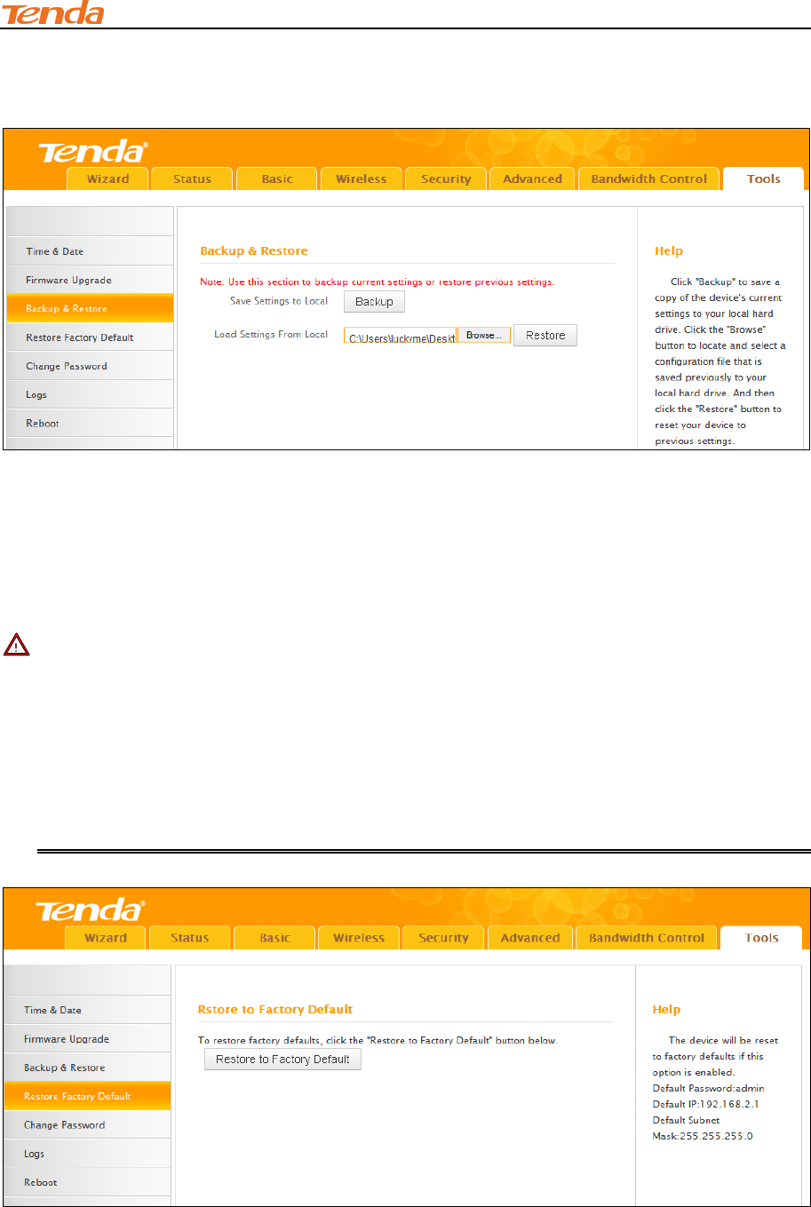
To Restore Configurations:
① Click Browse.
② Select the configuration file that is saved previously to your local hard drive and click Open.
III Features & Configurations
74
③ Click the Restore button to reset your device to previous settings.
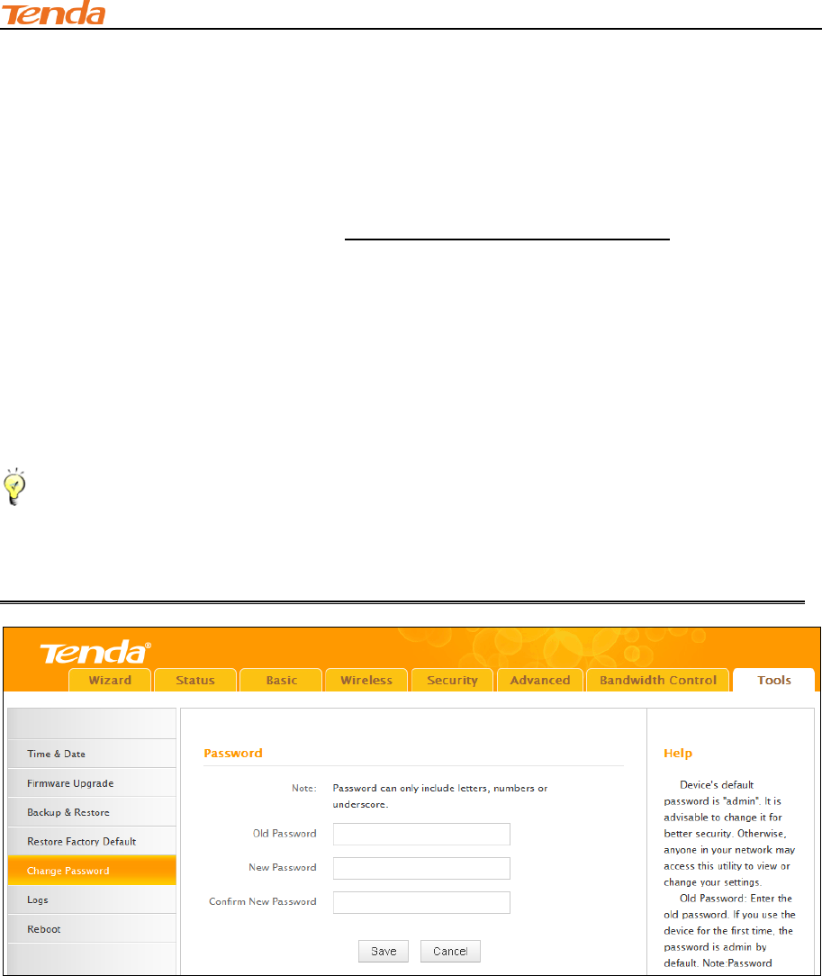
7.4 Restore to Factory Default Settings
Click Tools -> Restore Factory Default to enter the configuration screen. Here you can reset the
device to factory default settings.
Note ---------------------------------------------------------------------------------------------------------------------
1. If you enable this option, all current settings will be deleted and be restored to factory default
values. You will have to reconfigure Internet connection settings and wireless settings.
2. Do not restore factory default settings unless the following happens:
You need to join a different network or unfortunately forget the login password.
You cannot access Internet and your ISP or our technical support asks you to reset the
router.
III Features & Configurations
75
The factory default settings are listed below:
IP Address: 192.168.2.1
Subnet Mask: Enter 255.255.255.0.
Password: admin
For device's factory default settings, see Appendix 3 Factory Default Settings.
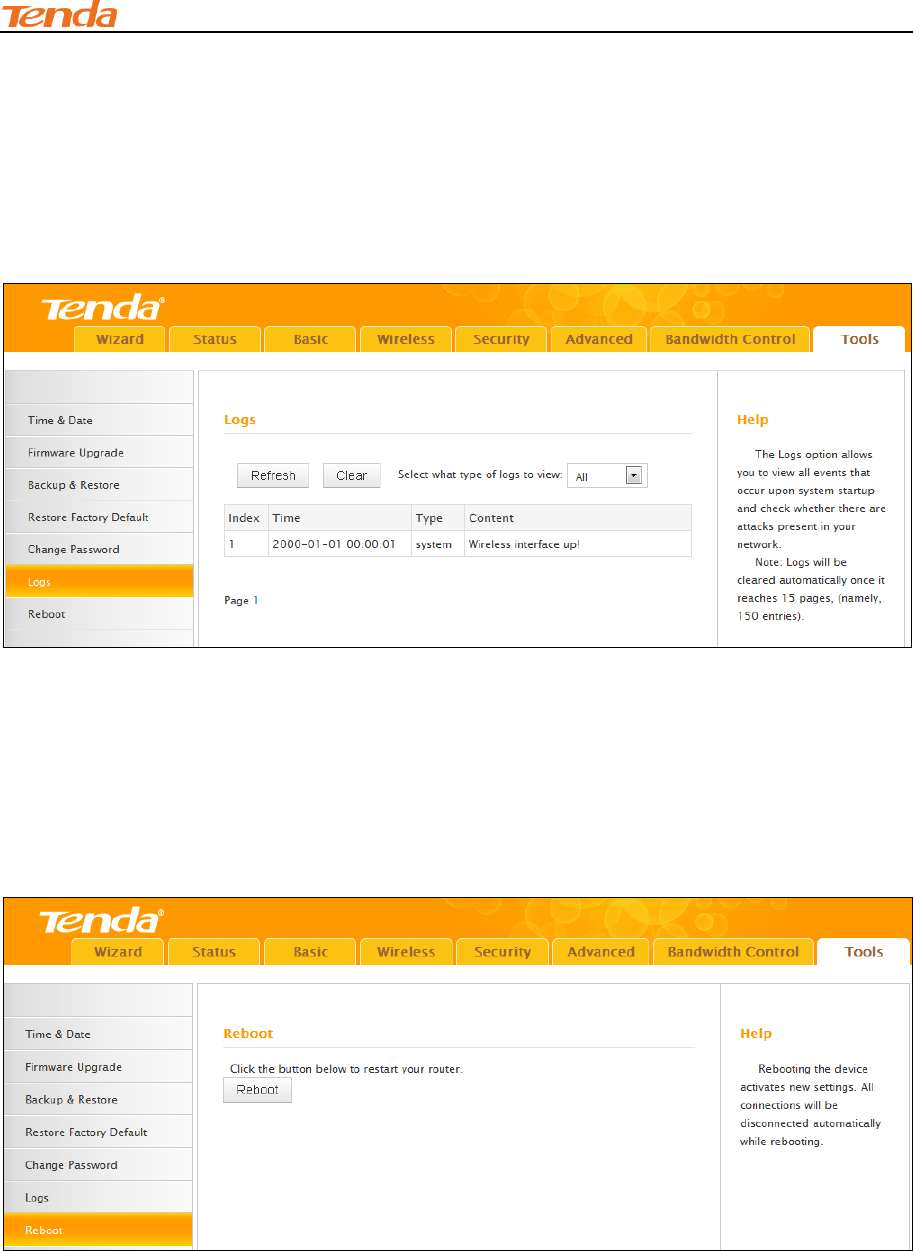
7.5 Change Password
Click Tools -> Change Password to enter the configuration screen. It is strongly recommended
that you change the factory default login password. Otherwise, anyone in your network can access
this utility to change your settings.
Tip------------------------------------------------------------------------------------------------------------------------------------------
1. The default login password is admin.
2. The valid password must be between 3~12 characters and only include letters, numbers and
underscore.
Configuration Procedures:
① Old Password: Enter the current login password.
② New Password: Input a new password.
③ Confirm New Password: Re-enter the new password for confirmation.
④ Click Save to save your settings.
III Features & Configurations
76
7.6 Logs
Click Tools -> Logs to enter the logs screen. Here you can view the history of the device’s actions
upon system startup.
Three types of logs are available: System, sntp and ddns.
7.7 Reboot
When a certain feature does not take effect or the device fails to function correctly, try rebooting
the device.
IV Appendix
77
IV Appendix
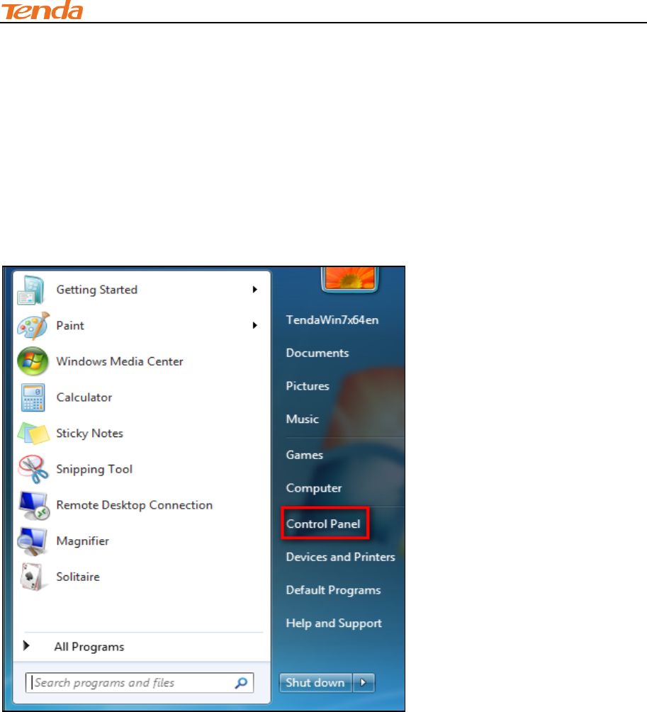
1 Configure PC TCP/IP Settings
Windows 7
① Click Start -> Control Panel.
IV Appendix
78
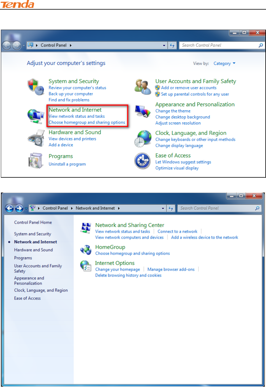
② Click Network and Internet.
③ Click Network and Sharing Center.
IV Appendix
79
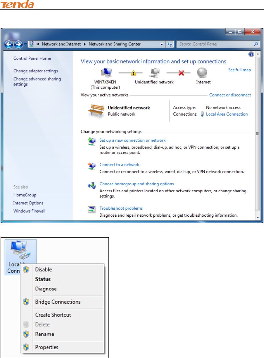
④ Click Change adapter settings.
⑤ Click Local Area Connection and select Properties.
IV Appendix
80
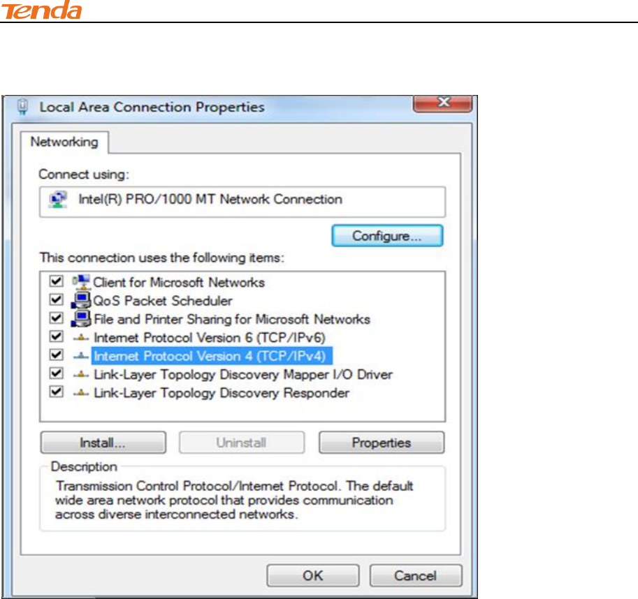
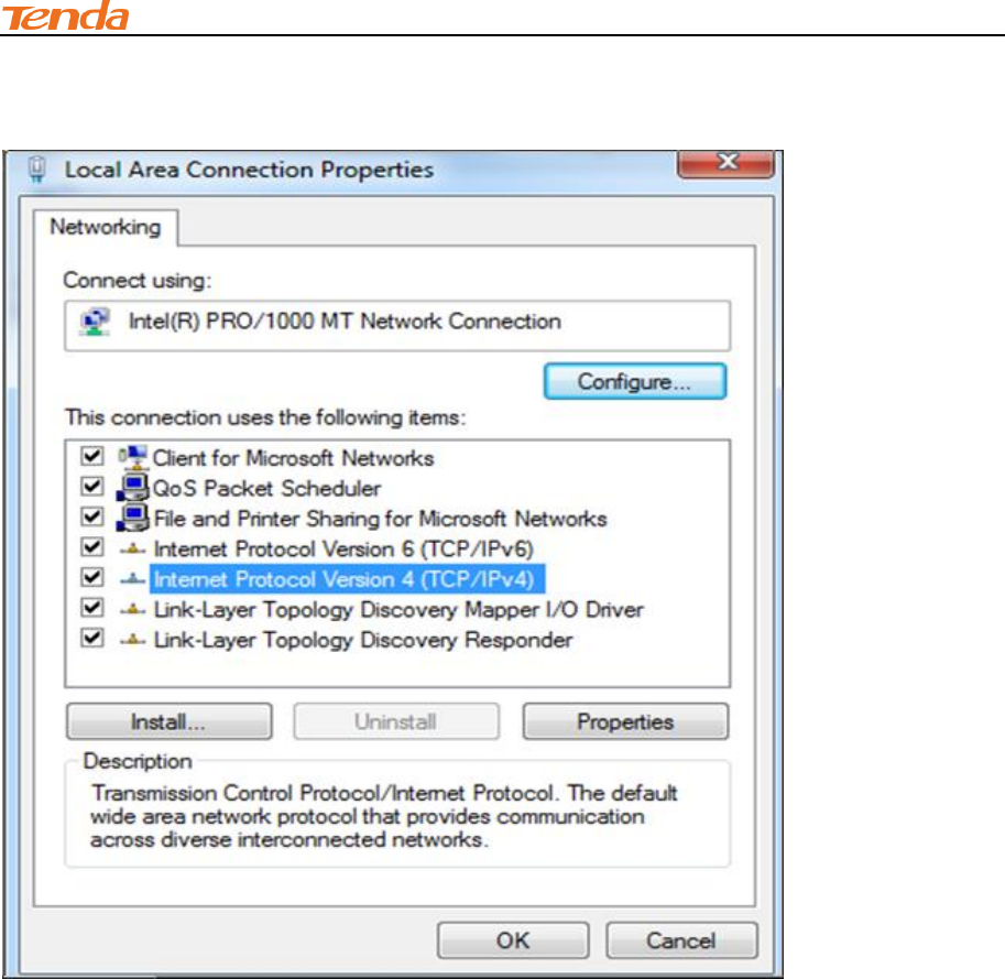
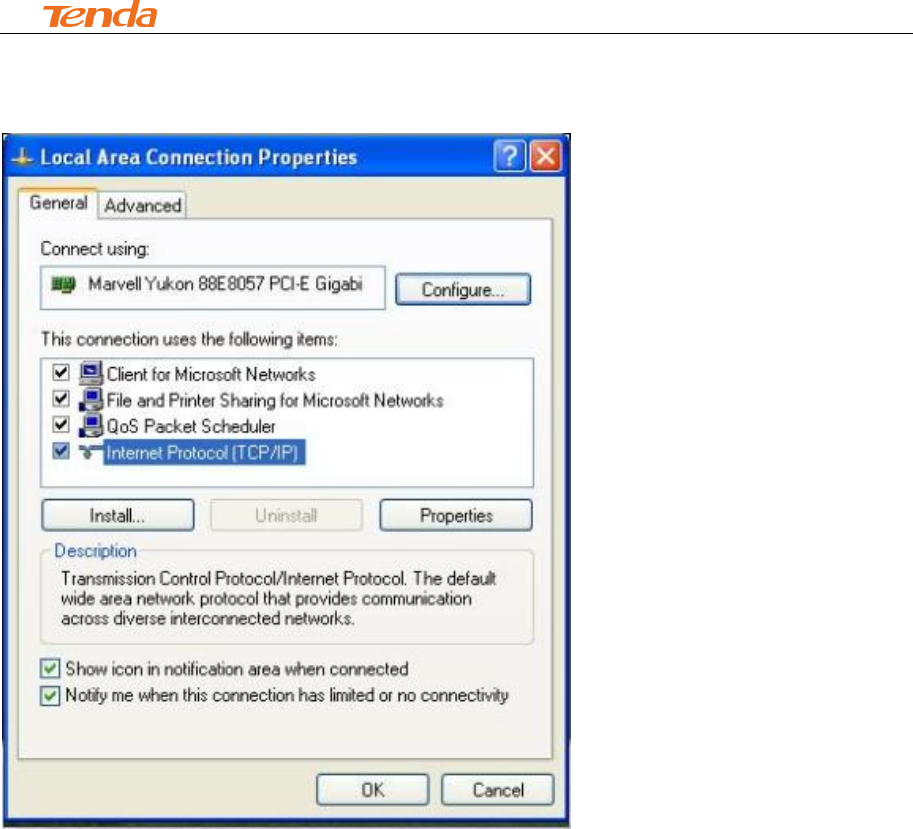
⑥ Select Internet Protocol Version 4 (TCP/IPv4) and click Properties.
IV Appendix
81
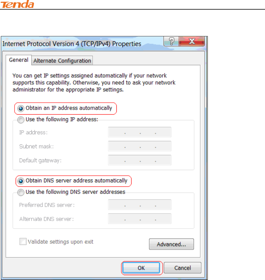
⑦ Select Obtain an IP address automatically and click OK.
IV Appendix
82
⑧ Click OK on the Local Area Connection Properties window to save your settings.
IV Appendix
83
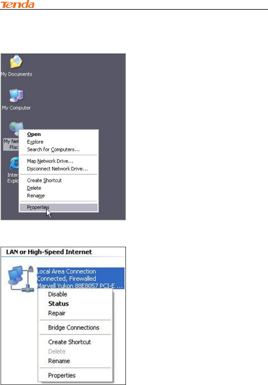
Windows XP
① Right-click My Network Places and select Properties.
② Right click Local Area Connection and select Properties.
IV Appendix
84
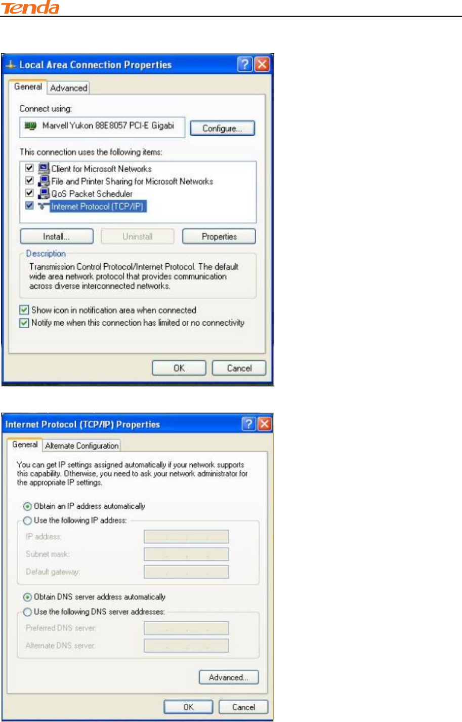
③ Select Internet Protocol Version 4 (TCP/IPv4) and click Properties.
④ Select Obtain an IP address automatically and click OK.
IV Appendix
85
⑤ Click OK on the Local Area Connection Properties window to save your settings.

IV Appendix
86
2 FAQs
This section provides solutions to problems that may occur during installation and operation of the
device. Read the following if you are running into problems.
If your problem is not covered here, please feel free to go to www.tendacn.com to find a solution or
email your problems to: support@tenda.com.cn or support02@tenda.com.cn. We will be more
than happy to help you out as soon as possible.
1. Q: I cannot access the device's management interface. What should I do?
Make sure the power LED on the device's front panel is on and the SYS LED blinks
normally.
Make sure all cables are correctly connected and the corresponding LAN LED on the
device is on.
Verify that your PC's TCP/IP settings are configured correctly. If you select the "Use the
following IP address" option, set your PC's IP address to any IP address between
192.168.2.2~192.168.2.254. Or you can select the "Obtain an IP address automatically"
option.
Delete your browser cache and cookies or use a new browser. Make sure you enter
192.168.2.1 in the address bar.
Open your browser and click Tools -> Internet Options -> Connections -> LAN
Settings, uncheck the Use a proxy server for your LAN option.
Press the WPS/RST button for about 10 seconds to restore your device to factory default
settings. Then log to your device again.
2. Q: I changed the login password and unfortunately forget it. What should I do?
Press the WPS/RST button for over 7 seconds to restore your device to factory default settings.
3. Q: My computer shows an IP address conflict error after having connected to the device.
What should I do?
Make sure there are no other DHCP servers on your LAN or other DHCP servers are
disabled.
Make sure the device's LAN IP is not used by other devices on your LAN. The device's
default LAN IP address is 192.168.2.1.

IV Appendix
87
Make sure the statically assigned IP addresses to the PCs on LAN are not used by others
PCs.
4. Q: I have problems connecting to Internet/Secure websites do not open or displays only
part of a web page. What should I do?
This problem mainly happens to users who use the PPPoE or Dynamic IP Internet connection type.
You need to change the MTU size. Try changing the MTU to 1450 or 1400. If this does not help,
gradually reduce the MTU from the maximum value until the problem disappears.
3 Factory Default Settings
The table below lists the factory default settings of your device.
Item
Default Settings
Router Login
Login IP Address
192.168.2.1
Login User Name
admin
Login Password
admin
Network
Settings
Internet Connection Type
Mode Auto-switch Enabled
MTU
1492 (PPPoE)
1500 (DHCP/Dynamic and Static IP)
WAN Speed
Auto
DNS
Disable
LAN Settings
(LAN)
IP Address
192.168.2.1
Subnet Mask
255.255.255.0
DHCP Server
Enabled
IP Pool
192.168.2.100~192.168.2.200
Time Zone
(GMT+08:00)Beijing, Chongquing, Hong
Kong, Urumqi
Wireless
Wireless
Enabled
SSID
Tenda_XXXXXX (where XXXXXX is the
last six characters in the device's MAC
address)
You can find it on the label attached to the
device.
Network Mode
11b/g/n mixed
SSID Broadcast
Enabled
Channel
AutoSelect
Channel Bandwidth
20/40
Extension Channel
AutoSelect
Wireless Security
Disabled
Wireless Access Control
Disabled
IV Appendix
88
Others
Remote Web Management
Disabled
Bandwidth Control
Disabled
DMZ Host
Disabled
UPnP
Enable
Internet Access Management
Disabled
4 Remove Wireless Network from Your PC
If you change wireless settings on your wireless device, you must remove them accordingly from
your PC; otherwise, you may not be able to wirelessly connect to this device. Below describes how
to remove a wireless network from your PC.
Windows 7
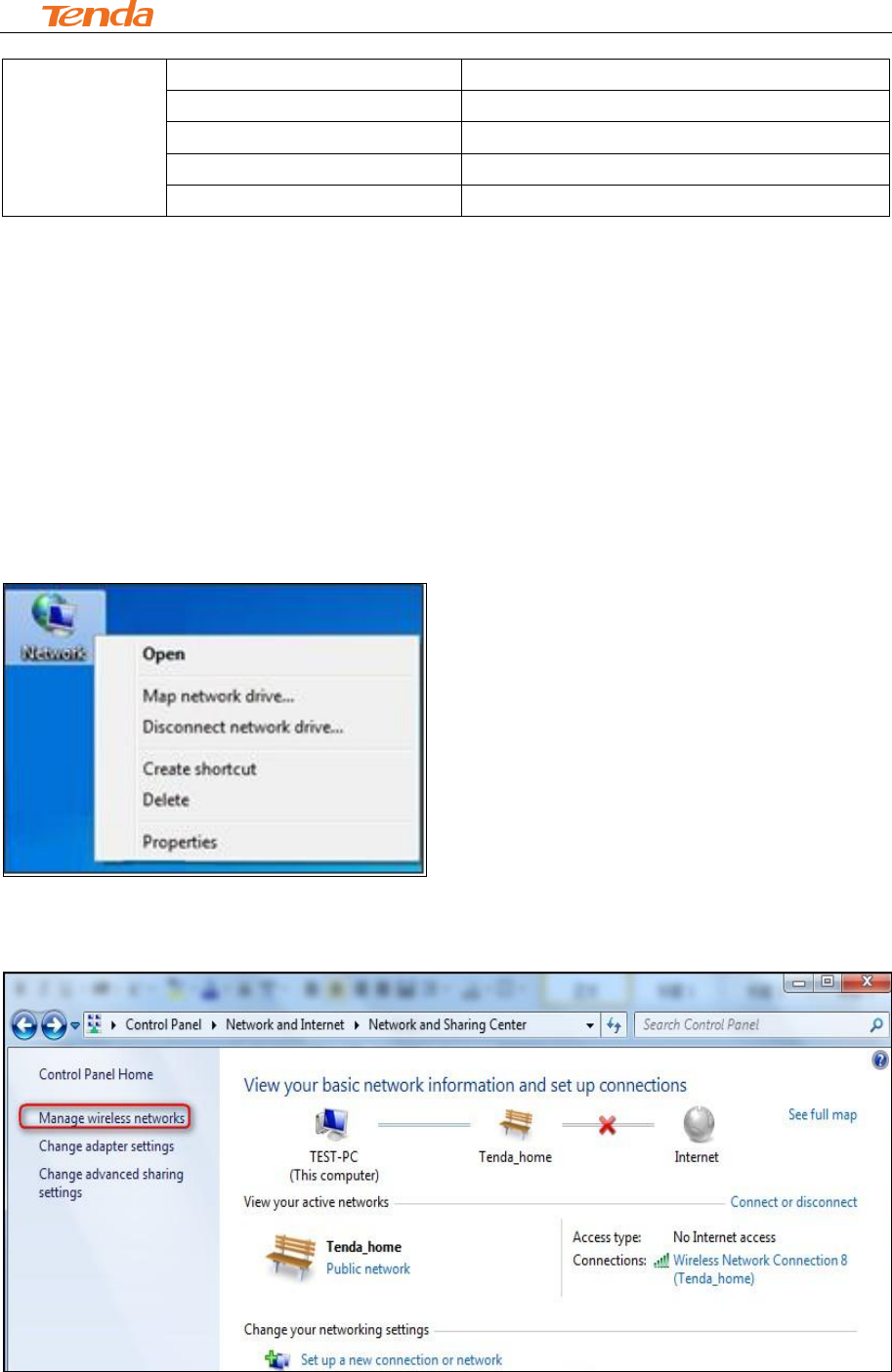
① Right-click the Network icon and select Properties.
② Select Manage Wireless Networks.
IV Appendix
89
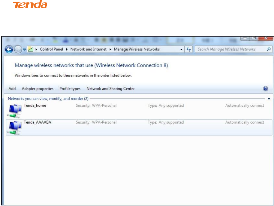
③ Select the wireless network and click Remove network.
IV Appendix
90
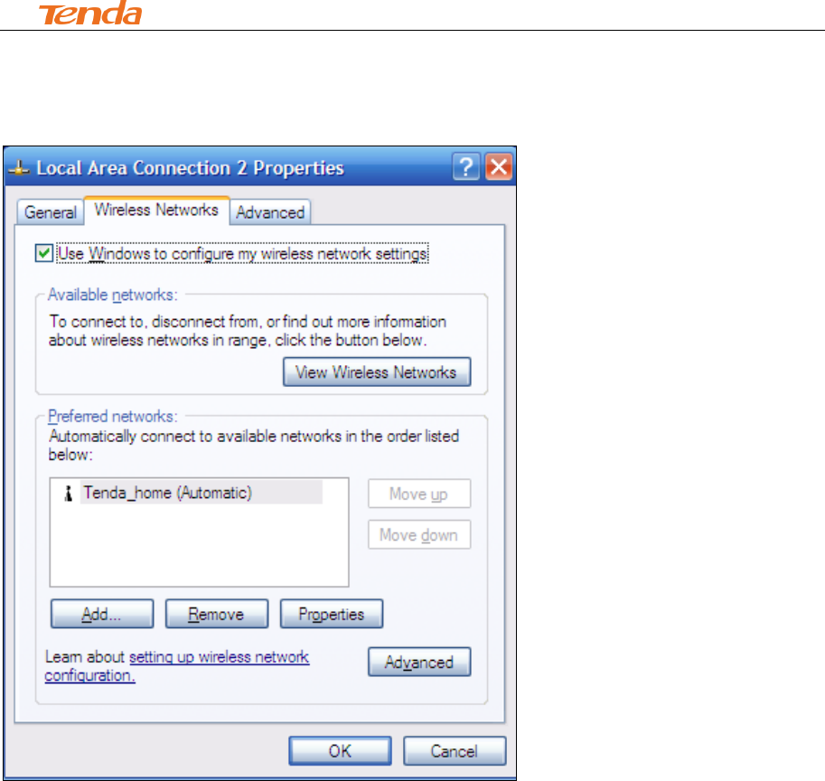
Windows XP
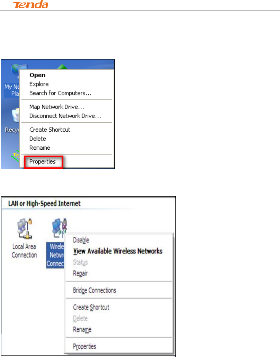
① Right-click My Network Places and select Properties.
② Right click Wireless Network Connection and then select Properties.
IV Appendix
91
③ Click Wireless Networks, select the wireless network name under Preferred networks and
then click the Remove button.

IV Appendix
92
5 Safety and Emission Statement
CE Mark Warning
This is a Class B product in a domestic environment, this product may cause radio interference, in
which case the user may be required to take adequate measures. This device complies with EU
1999/5/EC.
NOTE: (1) The manufacturer is not responsible for any radio or TV interference caused by
unauthorized modifications to this equipment.(2) To avoid unnecessary radiation interference, it is
recommended to use a shielded RJ45 cable
FCC Statement
This device complies with Part 15 of the FCC Rules. Operation is subject to the following two
conditions: (1) This device may not cause harmful interference, and (2) this device must accept
any interference received, including interference that may cause undesired operation.
This equipment has been tested and found to comply with the limits for a Class B digital device,
pursuant to Part 15 of the FCC Rules. These limits are designed to provide reasonable
protection against harmful interference in a residential installation. This equipment generates,
uses and can radiate radio frequency energy and, if not installed and used in accordance with the
instructions, may cause harmful interference to radio communications. However, there is no
guarantee that interference will not occur in a particular installation. If this equipment does cause
harmful interference to radio or television reception, which can be determined by turning the
equipment off and on, the user is encouraged to try to correct the interference by one of the
following measures:
- Reorient or relocate the receiving antenna.
- Increase the separation between the equipment and receiver.

IV Appendix
93
- Connect the equipment into an outlet on a circuit different from that
to which the receiver is connected.
- Consult the dealer or an experienced radio/TV technician for help.
FCC Caution: Any changes or modifications not expressly approved by the party responsible for
compliance could void the user's authority to operate this equipment.
This transmitter must not be co-located or operating in conjunction with any other antenna or
transmitter.
The manufacturer is not responsible for any radio or TV interference caused by unauthorized
modifications to this equipment.
Radiation Exposure Statement
This equipment complies with FCC radiation exposure limits set forth for an uncontrolled
environment. This equipment should be installed and operated with minimum distance 20cm
between the radiator & your body.
NOTE:(1)The manufacturer is not responsible for any radio or TV interference caused by
unauthorized modifications to this equipment.(2) To avoid unnecessary radiation interference, it is
recommended to use a shielded RJ45 cable
NCC Notice
經型式認證合格之低功率射頻電機,非經許可,公司、商號或使用者均不得擅自變更頻率、加大功
率或變更設計之特性及功能。
低功率射頻電機之作用不得影響飛航安全及幹擾合法通信;經發現有幹擾現象時,應立即停用,並
改善至無幹擾時方得繼續使用。前項合法通信,指依電信規定作業之無線電信。低功率射頻電機須
忍受合法通信或工業、科學及醫療用電波輻射性電機設備之幹擾。