TENDA TECHNOLOGY D151 ADSL Router User Manual
SHENZHEN TENDA TECHNOLOGY CO., LTD. ADSL Router
Contents
- 1. Users Manual Part 1
- 2. Users Manual Part 2
Users Manual Part 2
Wireless Modem Router User Guide
- 51 -
_________________________________________________________________________________________________
Warning!
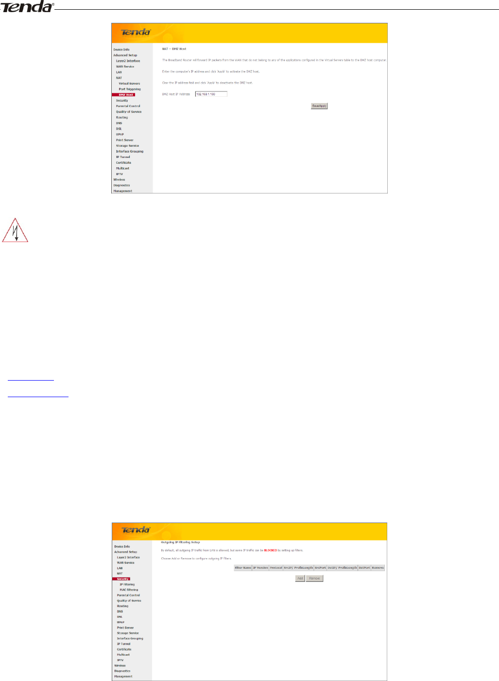
DMZ servers pose a security risk. A computer designated as the DMZ server loses much of the protection of the firewall
and is exposed to exploits from the Internet.
_________________________________________________________________________________________________
4.2.5 Security
This section explains the following information:
• IP Filtering
• MAC Filtering
IP Filtering
Outgoing IP Filtering Setup
By default, all outgoing IP traffic from LAN is allowed, but some IP traffic can be BLOCKED by setting up filters.
Choose Add or Remove to configure outgoing IP filters.
Choose Add to enter the following screen:
Wireless Modem Router User Guide
- 52 -
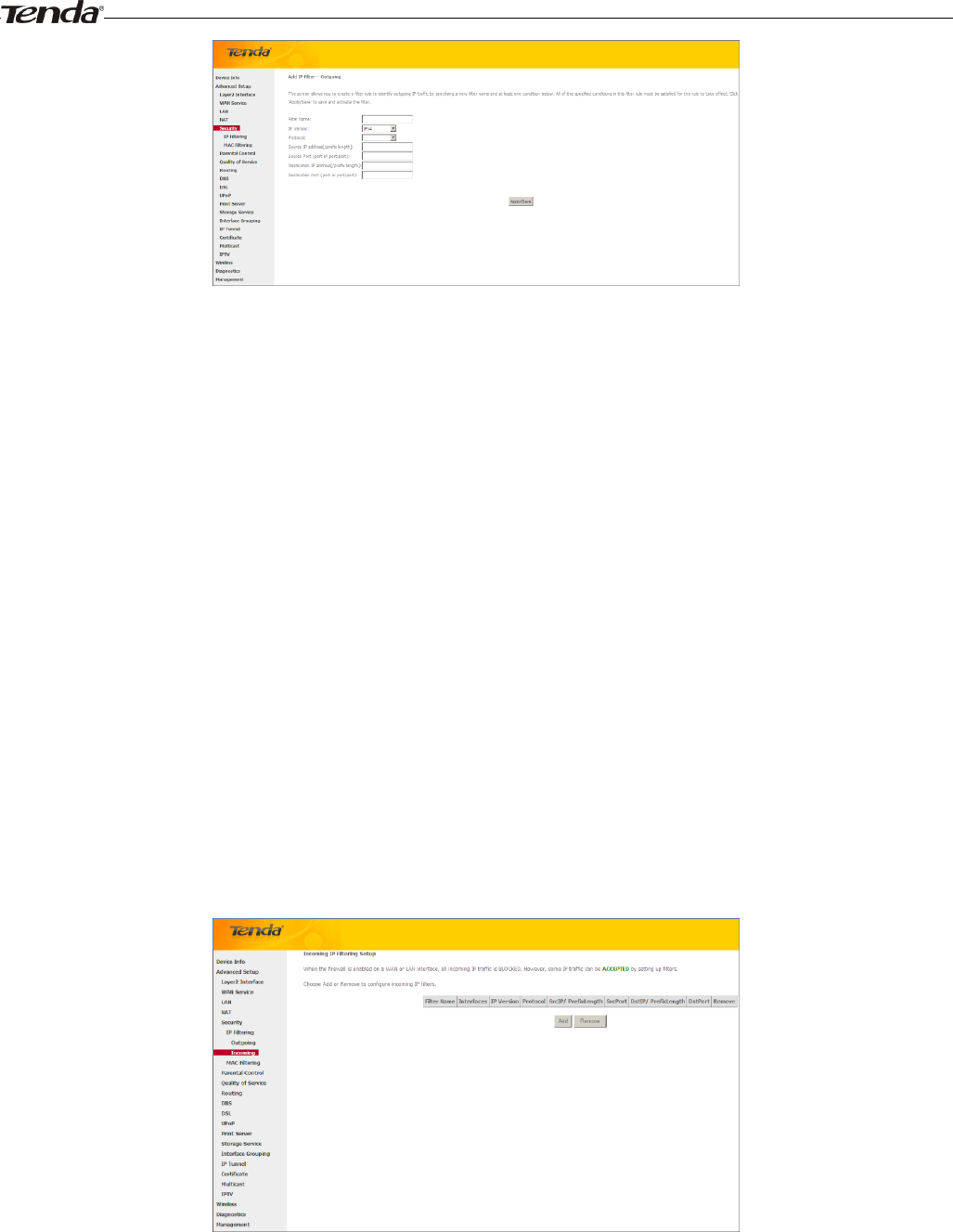
This screen allows you to create a filter rule to identify outgoing IP traffic by specifying a new filter name and at least
one condition below. All of the specified conditions in this filter rule must be satisfied for the rule to take effect. Click
'Apply/Save' to save and activate the filter.
Filter Name: Enter a descriptive filtering name.
IP Version: Select either IPv4 or IPv6.
Protocol: TCP/UDP, TCP, UDP and ICMP are available for your option.
Source IP address [/prefix length]: Enter the LAN IP address to be filtered.
Source Port (port or port: port): Specify a port number or a range of ports used by LAN PCs to access Internet. If
you are unsure, leave it blank.
Destination IP address [/prefix length]: Specify the external network IP address to be accessed by specified LAN
PCs.
Destination Port (port or port:port): Specify a port number or a range of ports used by LAN PCs to access external
network.
Incoming IP Filtering Setup
When the firewall is enabled on a WAN or LAN interface, all incoming IP traffic is BLOCKED. However, some IP
traffic can be ACCEPTED by setting up filters.
Choose Add or Remove to configure incoming IP filters.
Click Add to enter the following screen:
Wireless Modem Router User Guide
- 53 -
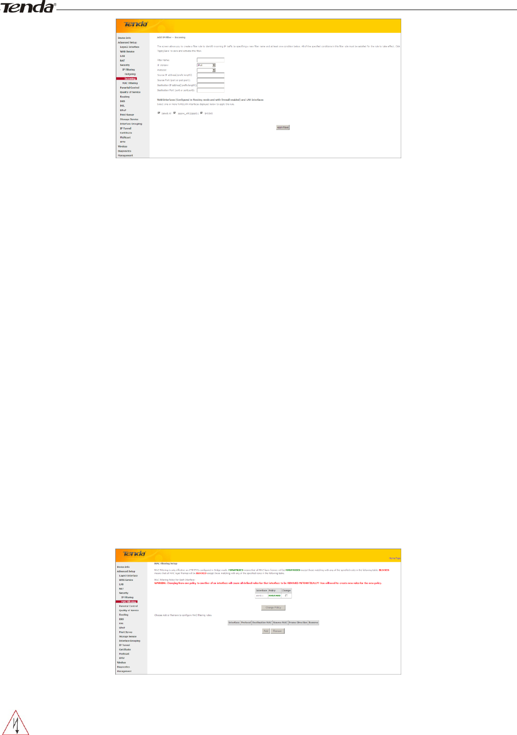
This screen allows you to create a filter rule to identify incoming IP traffic by specifying a new filter name and at least
one condition below. All of the specified conditions in this filter rule must be satisfied for the rule to take effect. Click
Apply/Save to save and activate the filter.
IP Version: Select either IPv4 or IPv6.
Protocol: TCP/UDP, TCP, UDP and ICMP are available for your option.
Source IP address [/prefix length]: Enter the Internal IP address [/prefix length] to be filtered.
Source Port (port or port: port): Specify a port number or a range of ports used by PCs from external network to
access your internal network.
Destination IP address [/prefix length]: Specify the internal network IP address [/prefix length] to be accessed by
the specified PCs from external network.
Destination Port (port or port:port): Specify a port number or a range of ports used by PCs from external network
to access your internal network.
MAC Filtering
A bridge WAN service is needed to configure this service.
MAC Filtering is only effective on ATM PVCs configured in Bridge mode. FORWARDED means that all MAC layer
frames will be FORWARDED except those matching with any of the specified rules in the following table. BLOCKED
means that all MAC layer frames will be BLOCKED except those matching with any of the specified rules in the
following table.
Choose Add or Remove to configure MAC filtering rules.
_________________________________________________________________________________________________
Warning!
Changing from one policy to another of an interface will cause all defined rules for that interface to be REMOVED
AUTOMATICALLY! You will need to create new rules for the new policy.
_________________________________________________________________________________________________
Wireless Modem Router User Guide
- 54 -
Click Add to enter the following screen:
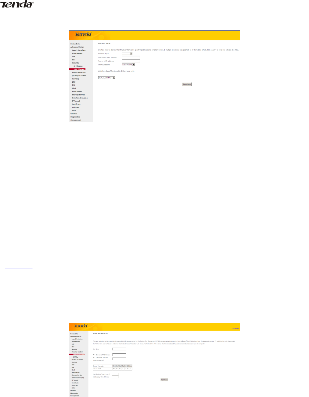
Here you can create a filter to identify the MAC layer frames by specifying at least one condition below. If multiple
conditions are specified, all of them take effect. Click Save/Apply to save and activate the filter.
Protocol Type: Select a protocol type from the drop-down list.
Destination MAC Address: Enter the destination MAC address apply the MAC filtering rule to which you wish to
apply the MAC filtering rule.
Source MAC Address: Enter the source MAC address to which you wish to apply the MAC filtering rule.
Frame Direction: Select a frame direction from the drop-down list.
WAN Interfaces: Select a WAN interface from the drop-down list.
4.2.6 Parental Control
This section explains the following information:
• Time Restriction
• URL Filter
Time Restriction
Click Parental Control -> Time Restriction -> Add to enter the following screen.
Here you can add time of day restriction that an attached LAN device can access Internet.
The 'Browser's MAC Address' automatically displays the MAC address of the LAN device where the browser is running.
To restrict other LAN device, click the "Other MAC Address" button and enter the MAC address of the other LAN
device.
User Name: Enter a user name.
Browser's MAC Address: Automatically adds the MAC address of the attached LAN device where the browser is
Wireless Modem Router User Guide
- 55 -
running.
Other MAC Address: Specify the MAC address of the computer that you want to apply Internet access restriction.
Days of the week: Click to select the days of the week during which you wish to restrict Internet access.
Start Blocking Time/ End Blocking Time: Specify time of day restriction to an attached LAN device. Within this
specified time length of the day, this LAN device will be blocked from Internet.
Apply/Save: Click to Apply/Save your settings.
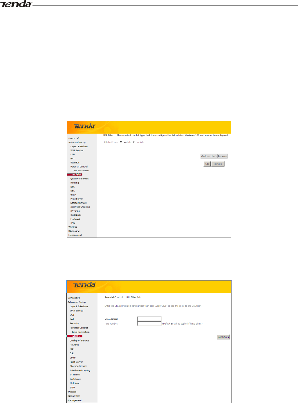
URL Filter
Here you can add URL access restriction to specific LAN PCs.
Select the URL List Type (Exclude or Include) first and then click Add to enter the screen below for configuring the list
entries. Maximum 100 entries can be configured.
URL Address: Enter the URLs that a specific LAN PC cannot access.
Port Number: Specify the port number used by the web server. The default is 80, which is the standard protocol for web
servers.
Enter the URL address and port number then click "Apply/Save" to add the entry to the URL filter.
Wireless Modem Router User Guide
- 56 -
_________________________________________________________________________________________________
Note:
If you have accessed the URL before you include it in a URL filter rule, you must reboot the router and erase it from your
PC to activate this URL filter rule. To erase the domain name from your PC, click Start -> Run, enter cmd and then type
ipconfig /flushdns.
_________________________________________________________________________________________________
4.2.7 Quality of Service
This section explains the following:
• QoS Queue
• QoS Classification
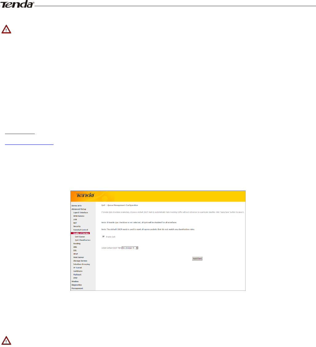
If Enable QoS checkbox is selected, choose a default DSCP mark to automatically mark incoming traffic without
reference to a particular classifier. Click Apply/Save button to save it.
Enable QoS: Check/uncheck to enable/disable the QoS feature.
_________________________________________________________________________________________________
Note:
1. If Enable Qos checkbox is not selected, all QoS will be disabled for all interfaces.
2. The default DSCP mark is used to mark all egress packets that do not match any classification rules.
_________________________________________________________________________________________________
QoS Queue
In ATM mode, maximum 8 queues can be configured.
In PTM mode, maximum 8 queues can be configured.
For each Ethernet interface, maximum 4 queues can be configured.
For each Ethernet WAN interface, maximum 4 queues can be configured.
To add a queue, click the Add button.
To remove queues, check their remove-checkboxes, then click the Remove button.
The Enable button will scan through every queues in the table. Queues with enable-checkbox checked will be enabled.
Wireless Modem Router User Guide
- 57 -
Queues with enable-checkbox un-checked will be disabled.
The enable-checkbox also shows status of the queue after page reload.
Note that if WMM function is disabled in Wireless Page, queues related to wireless will not take effects.
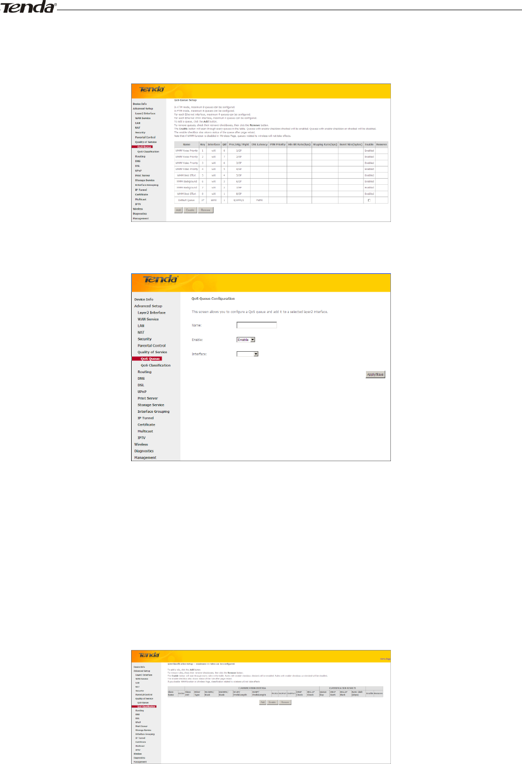
To add a queue, click the Add button to enter the following screen.
Here you can configure a QoS queue and add it to a selected layer2 interface.
QoS Classification
To add a rule, click the Add button.
To remove rules, check their remove-checkboxes, then click the Remove button.
The Enable button will scan through every rules in the table. Rules with enable-checkbox checked will be enabled.
Rules with enable-checkbox un-checked will be disabled.
The enable-checkbox also shows status of the rule after page reload.
If you disable WMM function in Wireless Page, classification related to wireless will not take effects.
Wireless Modem Router User Guide
- 58 -
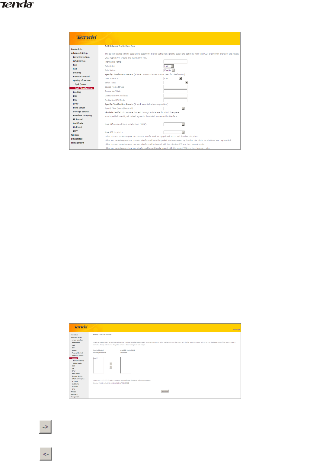
To add a rule, click the Add button to enter the following screen.
Here you can create a traffic class rule to classify the ingress traffic into a priority queue and optionally mark the DSCP
or Ethernet priority of the packet.
Click Apply/Save to save and activate the rule.
4.2.8 Routing
This section explains the following:
• Default Gateway
• Static Route
Default Gateway
Default gateway interface list can have multiple WAN interfaces served as system default gateways but only one will be
used according to the priority with the first being the highest and the last one the lowest priority if the WAN interface is
connected. Priority order can be changed by removing all and adding them back in again.
Selected Default Gateway Interfaces: Displays the selected dfault gteway iterfaces. Select a WAN interface and
click the button to move it to the Available Routed WAN Interfaces box.
Available Routed WAN Interfaces: Displays the available routed WAN interfaces. Select a WAN interface and
click the button to add it to the Selected Default Gateway Interfaces box.
Apply/Save: Click to save and activate your settings.
Wireless Modem Router User Guide
- 59 -
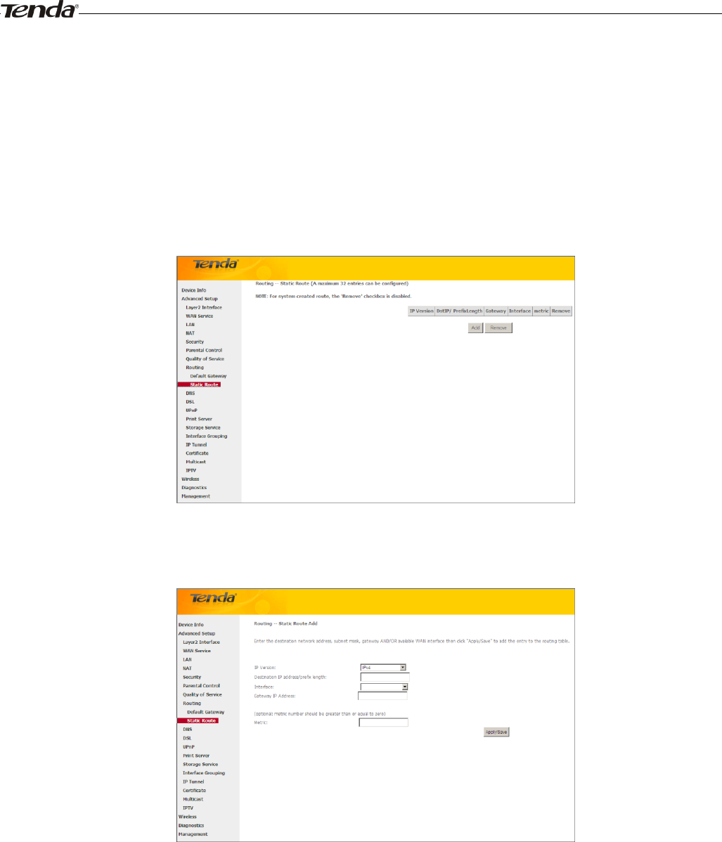
Static Route
Static routes provide additional routing information to your router. Typically, you do not need to add static routes.
However, when there are several routers in the network, you may want to set up static routing. Static routing determines
the path of the data in your network. You can use this feature to allow users on different IP domains to access the Internet
via this device. It is not recommended to use this setting unless you are familiar with static routing. In most cases,
dynamic routing is recommended, because this feature allows the router to detect the physical changes of the network
layout automatically. If you want to use static routing, make sure the router’s DHCP function is disabled.
Click Add to enter the following screen:
IP Version: Select either IPv4 or IPv6.
Destination IP address/prefix length: Enter the destination IP address and prefix length of the final destination.
Interface: Select an interface from the drop-down list.
Gateway IP address: Enter the gateway IP address, which must be a router on the same LAN segment as the
router.
Metric: Enter a number in the Metric field. This stands for the number of routers between your network and the
destination.
Apply /Save: Click to apply and save your settings.
Wireless Modem Router User Guide
- 60 -
_________________________________________________________________________________________________
Note:
1. Destination IP address cannot be on the same IP segment as WAN or LAN segment as the router.
2. Only configure additional static routes for unusual cases such as multiple routers or multiple IP subnets located on
your network. Wrong static routes may lead to network failure.
3. For system created route, the 'Remove' checkbox is disabled.
_________________________________________________________________________________________________
4.2.9 DNS
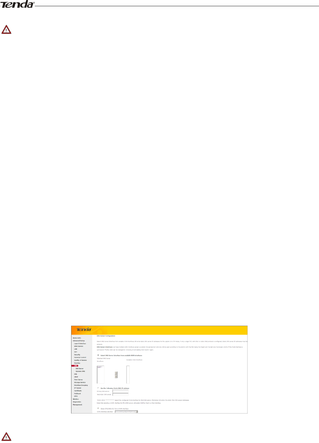
DNS Server (Static DNS)
The DNS server translates domain names to numeric IP addresses. It is used to look up site addresses based on their
names.
Select DNS Server Interface from available WAN interfaces OR enter static DNS server IP addresses for the system.
Here you can configure the WAN DNS address:
For IPv4:
-Click the Select DNS Server Interface from available WAN interfaces option
-OR select the Use the following Static DNS IP address option and enter static DNS server IP addresses for the system
And then click Apply/Save.
For IPv6:
-Select Obtain IPv6 DNS info from a WAN interface and Select a configured WAN interface for the IPv6 DNS server
information.
-Select Use the following Static IPv6 DNS address and enter the static IPv6 DNS server Addresses.
And then click Apply/Save.
_________________________________________________________________________________________________
Note:
1. DNS Server Interfaces can have multiple WAN interfaces served as system dns servers but only one will be used
according to the priority with the first being the higest and the last one the lowest priority if the WAN interface is
connected. Priority order can be changed by removing all and adding them back in again.
Wireless Modem Router User Guide
- 61 -
2. In ATM mode, if only a single PVC with IPoA or static IPoE protocol is configured, Static DNS server IP addresses
must be entered.
3. If you cannot locate the static DNS server IP information, ask your ISP to provide it.
4. The default settings are recommended if you are unsure about the DNS server addresses. If a wrong DNS server
address is configured, webpages may not be open.
_________________________________________________________________________________________________
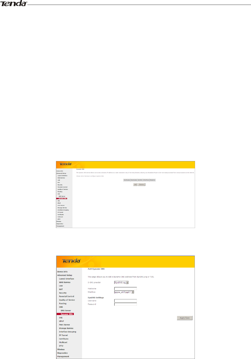
Dynamic DNS (DDNS)
If your Internet service provider (ISP) gave you a static (fixed) public IP address, you can register a domain name and
have that name associated with your IP address by public Domain Name Servers (DNS). However, if your ISP gave you
a dynamic (changing) public IP address, you cannot predict what your IP address will be, and the address can change
frequently. In this case, you can use a commercial Dynamic DNS service. It lets you register your domain to their IP
address and forwards traffic directed at your domain to your frequently changing IP address.If your ISP assigns a private
WAN IP address (such as 192.168.x.x or 10.x.x.x), the Dynamic DNS service does not work because private addresses
are not routed on the Internet.
Click Advanced Setup -> DNS -> Dynamic DNS to enter the Dynamic DNS screen.
Click the Add button to configure the DDNS settings.
D-DNS Provider: Select your DDNS service provider from the drop-down menu.
Wireless Modem Router User Guide
- 62 -
Hostname: Enter the DDNS domain name registered with your DDNS service provider.
Interface: Specify a WAN connection interface.
User Name: Enter the DDNS user name registered with your DDNS service provider.
Password: Enter the DDNS Password registered with your DDNS service provider.
Click Apply/Save to save your settings.
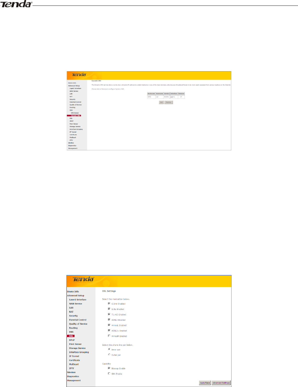
4.2.10 DSL
This screen provides multiple ASDL modulation modes to meet diversified environments. You can also select phone line
pair and Capability.
DSL parameter configurations must be supported by ISP to take effect. Actual parameters (see Statistics-xDSL) resulted
from the negotiation between your router and ISP. Wrong configurations may fail your Internet access.
The best DSL configurations are the factory defaults. Only change them if you are instructed by your ISP or our
technical staff when your router fails to negotiate with ISP in DSL (ATM) mode. Usually, this failure can be identified
and confirmed if the ADSL LED on the device keeps displaying a slow or quick blinking light.
Check the checkbox next to a modulation to enable it and then click Apply/Save.
Advanced Settings: Click to enter the Advanced Settings screen as below.
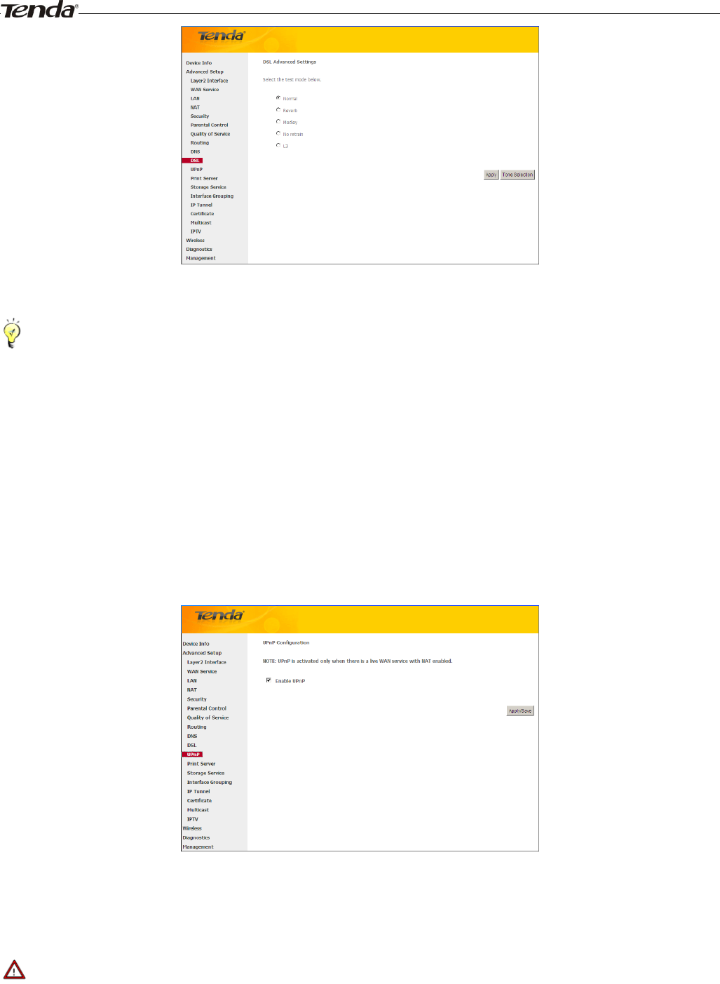
Wireless Modem Router User Guide
- 63 -
Here you can select the test mode and tone.
_________________________________________________________________________________________________
Tip:
If you are unsure about the ADSL parameters, please apply the factory default settings.Wrong configurations may fail
your Internet access.
_________________________________________________________________________________________________
4.2.11 UPnP
UPnP (Universal Plug and Play) allows Windows based systems to configure the device for various Internet applications
automatically. UPnP devices can automatically discover the services from other registered UPnP devices on the network.
If you use applications such as multiplayer gaming, peer-to-peer connections, or real-time communications, such as
instant messaging or remote assistance (a feature in Windows XP), you should enable UPnP.
Enable UPnP: Check/uncheck to enable/disable the UPnP feature.
_________________________________________________________________________________________________
Note:
UPnP is activated only when there is a live WAN service with NAT enabled.
_________________________________________________________________________________________________
Wireless Modem Router User Guide
- 64 -
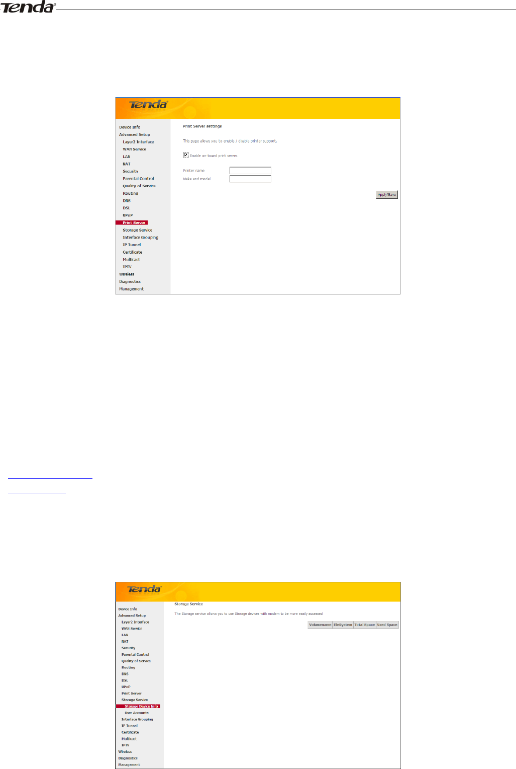
4.2.12 Print Server (Available only in D301)
This page allows you to enable / disable printer support.
Enable on-board print server: Check/uncheck to enable / disable the printer support.
Printer name: Enter a descriptive name of your printer.
Make and model: Enter the make and model of your printer.
Apply/Save: Click to apply and save your settings.
4.2.13 Storage Service (Available only in D301)
The Storage service allows you to use Storage devices with the modem router to be more easily accessed.
This section explains the following:
• Storage Device Info
• User Account
Storage Device Info
This screen displays the information of the storage device as seen on the screenshot below.
Wireless Modem Router User Guide
- 65 -
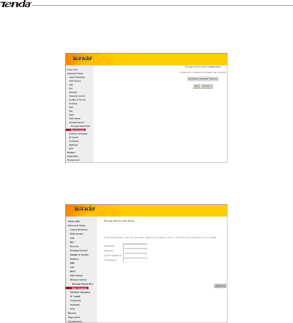
User Account
This section allows you to Add, or Remove User Accounts.
To add a user account:
1. Click Add to enter the following screen:
2. Enter the user name, password and volume name on which the home directory is to be created.
3. Click Apply/Save to apply and save your settings.
To remove an existing user account:
1. Check Remove next to the user account.
2. Click the Remove button.
4.1.14 Interface Grouping
Interface Grouping supports multiple ports to PVC and bridging groups. Each group will perform as an independent
network. To support this feature, you must create mapping groups with appropriate LAN and WAN interfaces using the
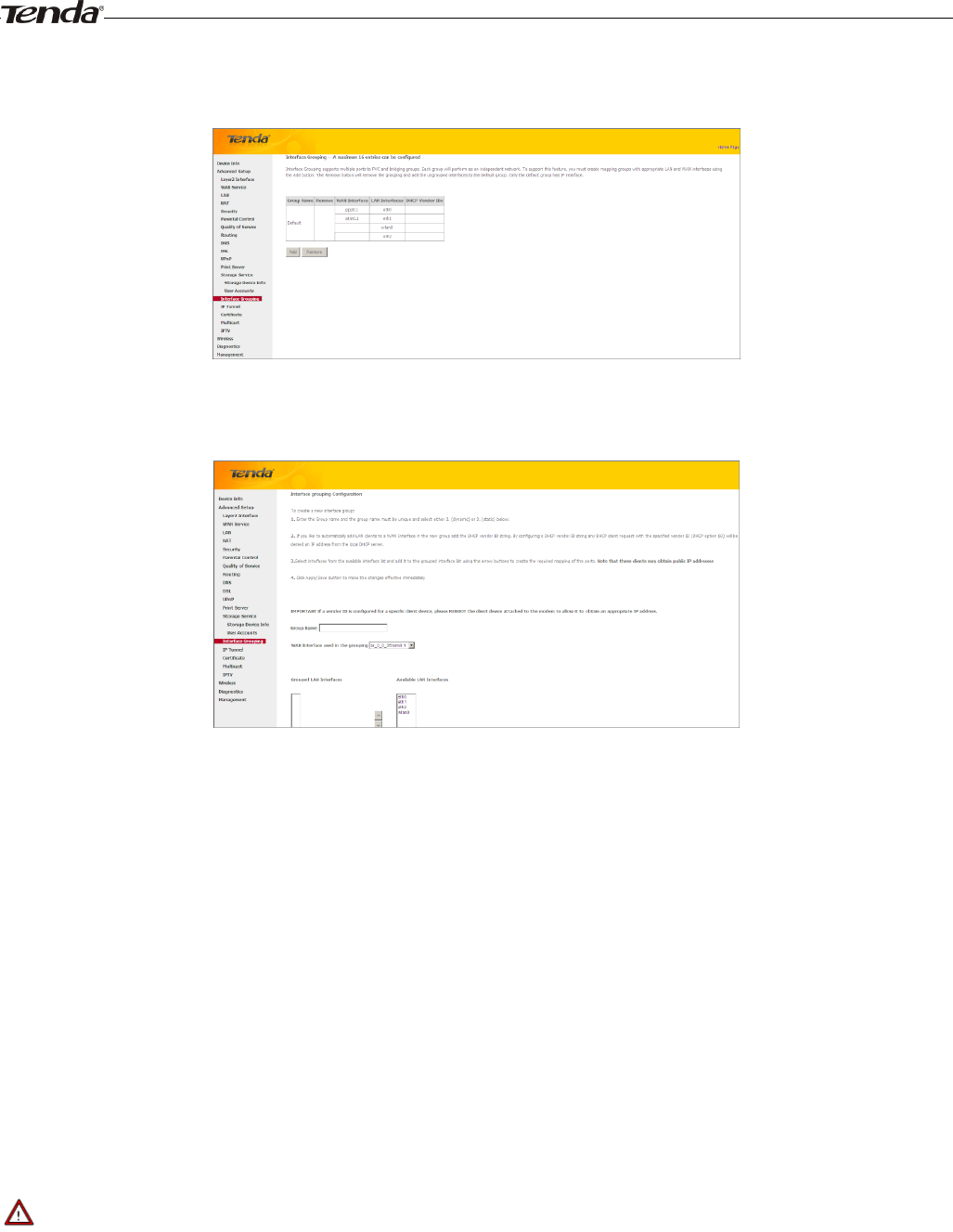
Wireless Modem Router User Guide
- 66 -
Add button. The Remove button will remove the grouping and add the ungrouped interfaces to the Default group. Only
the default group has IP interface.
Click Add to enter the screen below:
Group Name: The name of a configured rule.
WAN Interface used in the grouping: WAN connection to which the interface grouping rules apply.
Available LAN Interfaces: LAN interfaces that can be used for interface grouping.
Grouped LAN Interfaces: LAN interfaces that use specified WAN interface.
To create a new interface group:
1. Enter the Group name and the group name must be unique and select either 2. (dynamic) or 3. (static) below:
2. If you like to automatically add LAN clients to a WAN Interface in the new group add the DHCP vendor ID string.
By configuring a DHCP vendor ID string any DHCP client request with the specified vendor ID (DHCP option 60)
will be denied an IP address from the local DHCP server.
3. Select interfaces from the available interface list and add it to the grouped interface list using the arrow buttons to
create the required mapping of the ports. Note that these clients may obtain public IP addresses.
4. Click Apply/Save button to make the changes effective immediately.
_________________________________________________________________________________________________
Note:
If a vendor ID is configured for a specific client device, please REBOOT the client device attached to the modem to
allow it to obtain an appropriate IP address.
_________________________________________________________________________________________________
Wireless Modem Router User Guide
- 67 -
4.1.15 IP Tunnel
This section explains the following information:
• IPv6inIPv4
• IPv4inIPv6
IPv6inIPv4
Click IPv6inIPv4 and Add to enter the following screen:
Tunnel Name: Specify the name of the tunnel.
Mechanism: Currently, only DS-Lite configuration is supported.
Associated WAN Interface: Specify the WAN iterface of the tunnel.
Associated LAN Interface: Specify the LAN iterface of the tunnel.
Manual: If you select Manual, configure the following settings also:
IPv4 Mask Length: Specify the IPv4 Mask Length.
6rd Prefix with Prefix Length: Specify the 6rd Prefix with Prefix Length.
Border Relay IPv4 Address: Specify the Border Relay IPv4 Address.
Automatic: If Automatic is selected, no configurations are required.
Apply/Save: Click to apply and save your settings.
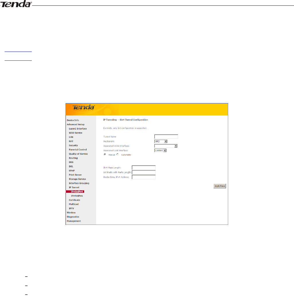
IPv4inIPv6
Click IPv4inIPv6 and Add to enter the following screen:
Wireless Modem Router User Guide
- 68 -
Tunnel Name: Specify the name of the tunnel.
Mechanism: Currently, only 6rd configuration is supported.
Associated WAN Interface: Specify the WAN iterface of the tunnel.
Associated LAN Interface: Specify the LAN iterface of the tunnel.
Manual: If you select Manual, enter the AFTR information also:
Automatic: If Automatic is selected, no configurations are required.
Apply/Save: Click to apply and save your settings.
4.1.16 Certificate
This section explains the following information:
• Local Certificates
• Trusted CA (Certificate Authority) Certificates
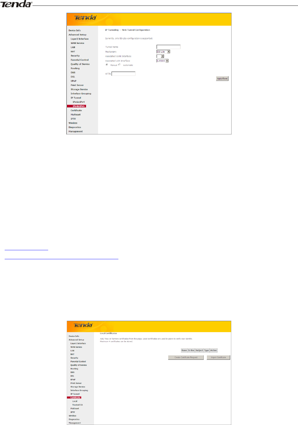
Local Certificates
Here you can Add, View or Remove certificates. Local certificates are used by peers to verify your identity. Maximum 4
certificates can be stored.
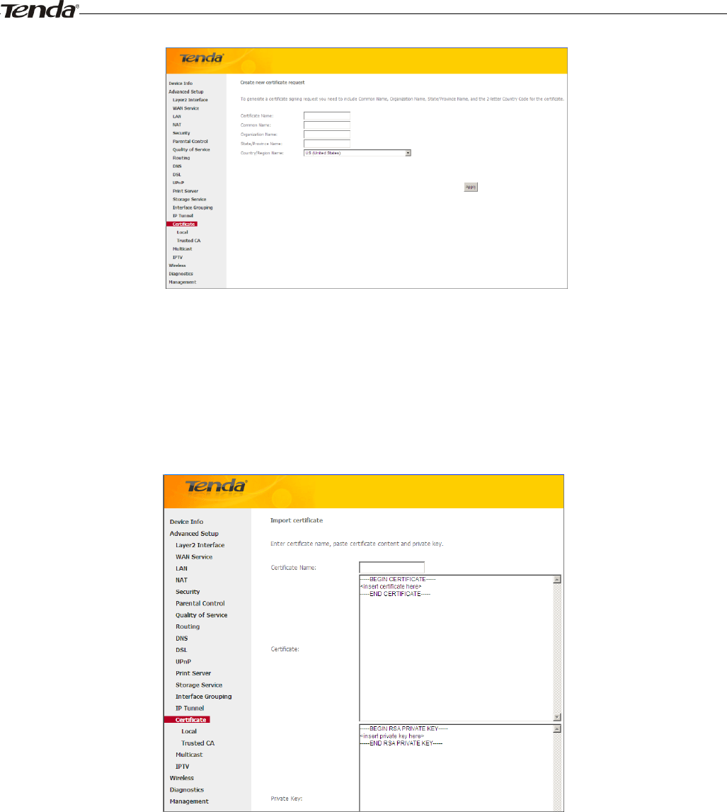
To generate generate a certificate signing request:
1. Click the Create Certificate Request button to enter the page below.
Wireless Modem Router User Guide
- 69 -
2. Specify the Common Name, Organization Name and State/Province Name
3. Enter the 2-letter Country Code for the certificate.
4. Click Apply to apply your settings.
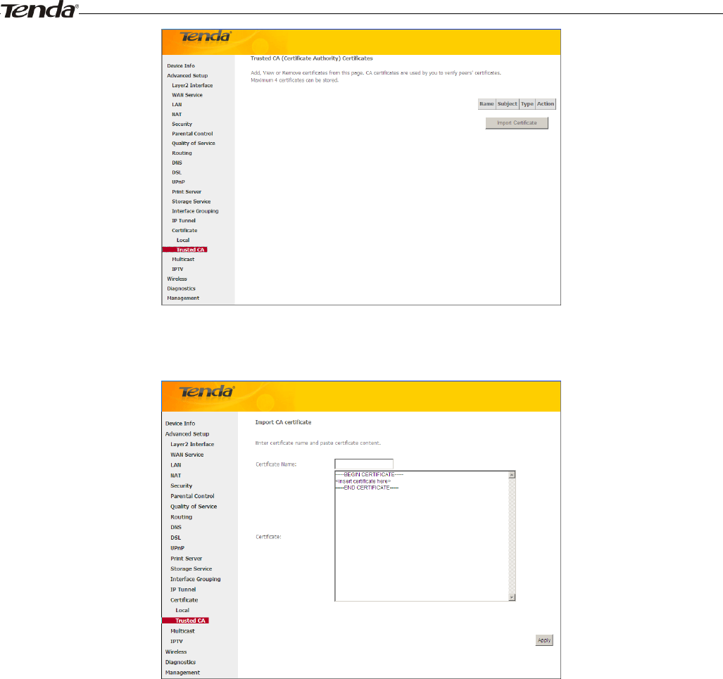
To Import certificate:
1. Click the Import Certificate button on the local certificates page to enter the page below.
2. Enter the certificate name.
3. Paste the certificate content and private key.
4. Click Apply to apply your settings.
Trusted CA (Certificate Authority) Certificates
Here you can Add, View or Remove CA certificates. CA certificates are used by you to verify peers' certificates.
Maximum 4 certificates can be stored.
Wireless Modem Router User Guide
- 70 -
To Import certificate:
1. Click the Import Certificate button to enter the page below.
2. Enter the certificate name.
3. Paste the certificate content.
4. Click Apply to apply your settings.
4.1.17 Multicast
Here you can configure the multicast feature.
To configure IGMP for IPv4
1. Check the LAN to LAN (Intra LAN) Multicast Enable box.
2. Check the Mebership Join Immediate (IPTV) box. This is only required for IPTV.
3. Keep other options unchanged from factory defaults if you are not an advanced user. This is strongly recommended.
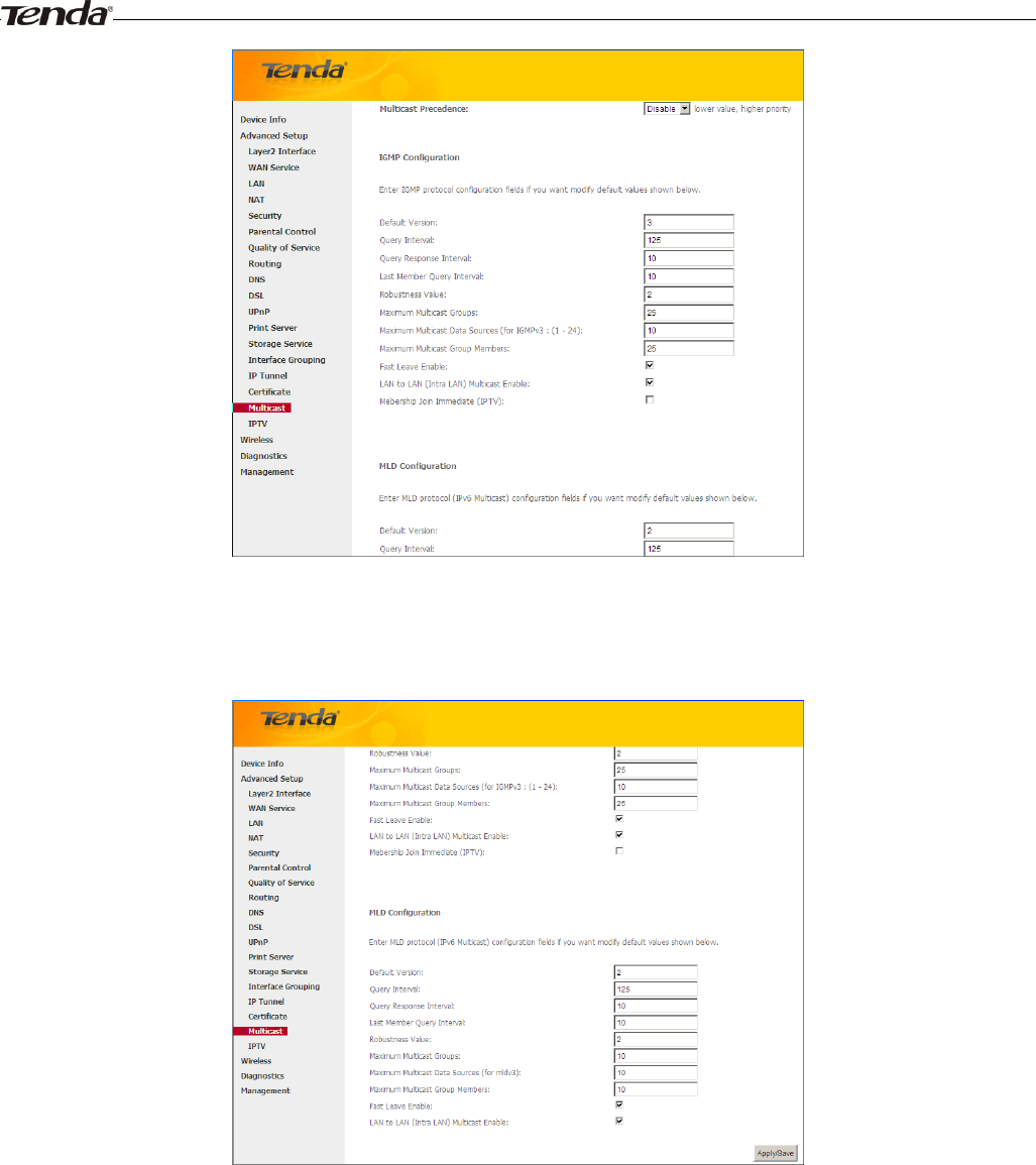
Wireless Modem Router User Guide
- 71 -
To configure IGMP for IPv6
1. Check the LAN to LAN (Intra LAN) Multicast Enable box.
2. Keep other options unchanged from factory defaults if you are not an advanced user. This is strongly recommended.
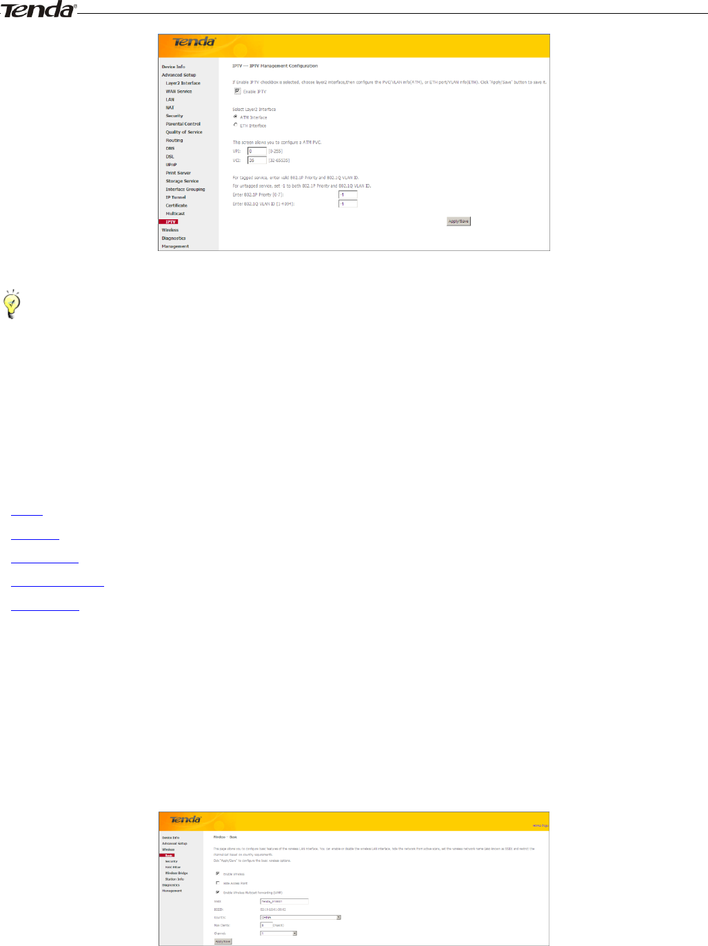
4.1.18 IPTV
If you check the Enable IPTV checkbox, you must choose a layer2 interface, and then configure the PVC/VLAN info
(ATM), or ETH port/VLAN info (ETH). Click Apply/Save button to save it.
Enable IPTV: Check/uncheck to enable/disable the IPTV service.
Wireless Modem Router User Guide
- 72 -
_________________________________________________________________________________________________
Tip:
For tagged service, enter valid 802.1P Priority and 802.1Q VLAN ID.
For untagged service, set -1 to both 802.1P Priority and 802.1Q VLAN ID.
_________________________________________________________________________________________________
4.3 Wireless
This section explains the following information:
• Basic
• Security
• MAC Filter
• Wireless Bridge
• Station Info
4.3.1 Basic
This page allows you to configure basic features of the wireless LAN interface. You can enable or disable the wireless
LAN interface, hide the network from active scans, set the wireless network name (also known as SSID) and restrict the
channel set based on country requirements.
Click Apply/Save to configure the basic wireless options.
Enable Wireless: check/uncheck to enable/disable the wireless feature.
SSID: This is thepublic name of your wireless network.
Hide SSID (Hide Access Point): This option allows you to have your network names (SSID) publicly broadcast or
if you choose to enable it, the SSID will be hidden.
BSSID:Display the BSSID.
Wireless Modem Router User Guide
- 73 -
Country: Select your country.
Max Clients: The max wireless clients your wireless network can accept. Up to 8 clients can join your wireless network
at a time. The default setting is 8.
Channel: Select a channel or select Auto to let system automatically select one for your wireless network to operate on
if you are unsure. The best selection is a channel that is the least used by neighboring networks.
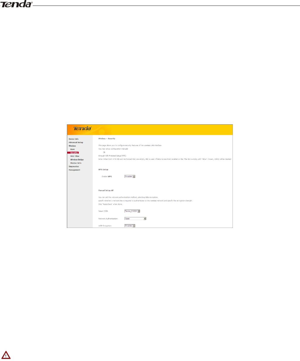
4.3.2 Security
This page allows you to configure security features of the wireless LAN interface. You may setup configuration
manually OR through WiFi Protcted Setup (WPS).
WPS Setup
Wi-Fi Protected Setup makes it easy for home users who know little of wireless security to establish a home network, as
well as to add new devices to an existing network without entering long passphrases or configuring complicated settings.
Simply enter a PIN code on the device web interface or press hardware WPS button (on the back panel of the device) and
a secure wireless connection is established.
WPS Button: Press the hardware WPS button on the device for 1 second and the WPS LED will keep blinking for about
2 minutes. Within the 2 minutes, press the WPS button on your wireless computer or other device. When the WPS
displays a solid light, the device has joined your wireless network.
PIN: To use this option, you must know the PIN code from the wireless client and enter it in the corresponding field on
your device while using the same PIN code on client side for such connection.
Enable WPS: Check/uncheck to enable/disable the WPS function. It is enabled by default.
_________________________________________________________________________________________________
Note:
1. To use the WPS security, the wireless client must be also WPS-capable.
2. When both STA PIN and Authorized MAC are empty, PBC is used. If Hide Access Point enabled or Mac filter list is
empty with "allow" chosen, WPS2 will be disabled.
_________________________________________________________________________________________________
Manual Setup AP
You can set the network authentication method, selecting data encryption, specify whether a network key is required to
authenticate to this wireless network and specify the encryption strength.
Click "Apply/Save" when done.
Wireless Modem Router User Guide
- 74 -
Network Authentication: Select Open, Shared, WPA-PSK, WPA2-PSK or Mixed WPA/ WPA2-PSK from the
drop-down list to encrypt your wireless network.
Depending on the type of network authentication you select, you will be prompted to enter corresponding settings.
WEP Encryption: Select Enabled or Disabled.
Encryption Strength: Select 128-bit or 64-bit.
Current Network Key: Select a network key to be active.
Network Key 1/2/3/4: Enter 13 ASCII characters or 26 hexadecimal digits for 128-bit encryption keys; enter 5 ASCII
characters or 10 hexadecimal digits for 64-bit encryption keys.
WPA/WAPI passphrase: Enter a WPA/WAPI network key.
WPA Group Rekey Interval: Specify a key update interval.
WPA/WAPI Encryption: Select AES or TKIP+AES.
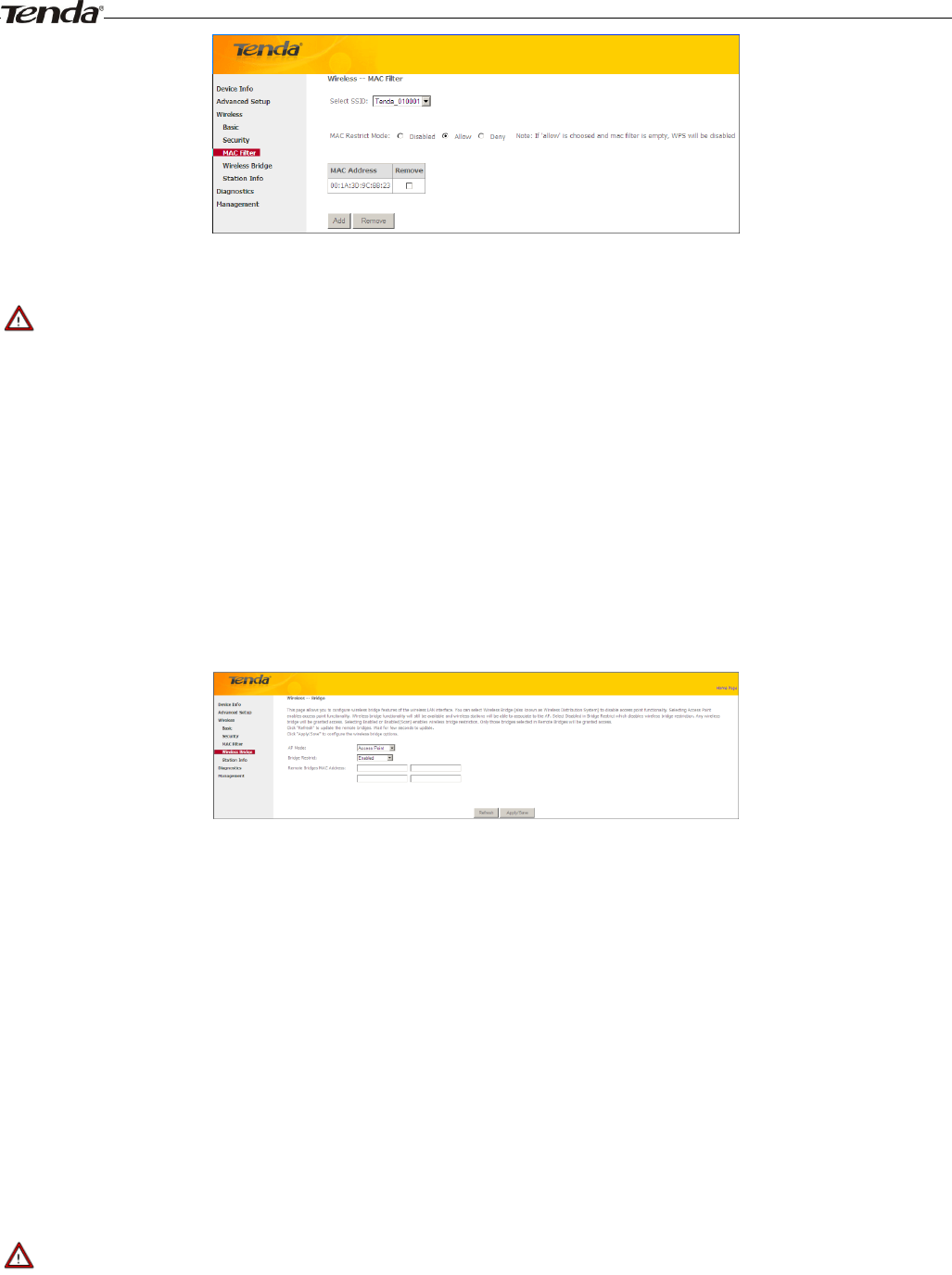
4.3.3 MAC Filter
The MAC-based Wireless Access Control feature can be used to allow or disallow clients to connect to your wireless
network.
Allow: Only allow PCs at specified MAC addresses (in the list) to connect to your wireless network.
Deny: Block only PCs at specified MAC addresses from connecting to your wireless network.
Disable: Disable this feature.
Add: Click to add a MAC address.
To delete an existing MAC address, first check the Remove box next to the MAC address in list and then click the
Remove button.
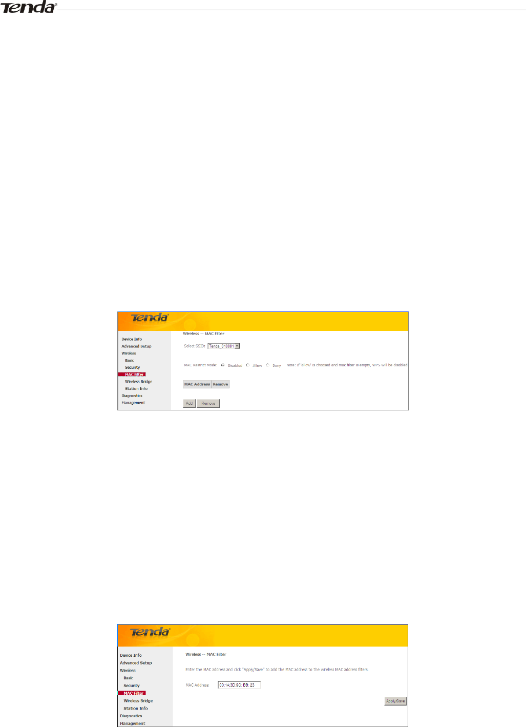
Example 1: To allow only the PC at the MAC address of 00:1A:3D:9C:BB:23 to connect to your wireless network, do as
follows:
1. Select Allow.
2. Click the Add button.
3. Enter 00:1A:3D:9C:BB:23 in the MAC address box as shown in the figure below:
4. Click Apply/Save.
Wireless Modem Router User Guide
- 75 -
_________________________________________________________________________________________________
Note:
If “allow” is choosed and mac filter is empty, WPS will be disabled.
_________________________________________________________________________________________________
4.3.4 Wireless Bridge
This page allows you to configure wireless bridge (also known as Wireless Distribution System) features of the wireless
LAN interface.
Wireless distribution system (WDS) is a system enabling the wireless interconnection of access points in an IEEE 802.11
network. It allows a wireless network to be expanded using multiple access points without the traditional requirement for
a wired backbone to link them.
AP Mode: You can select Wireless Bridge (also known as Wireless Distribution System) to disable access point
functionality. Selecting Access Point enables access point functionality. Wireless bridge functionality will still be
available and wireless stations will be able to associate to the AP.
Bridge Restrict: There are three options available: Enabled, Enabled (Scan) and Disabled. Select Disabled in Bridge
Restrict which disables wireless bridge restriction. Any wireless bridge will be granted access. Selecting Enabled or
Enabled (Scan) enables wireless bridge restriction. Only those bridges selected in Remote Bridges will be granted access.
The Enabled (Scan) enables wireless bridge restriction and automatically scans the remote bridges.Remote Bridges
MAC Address: Specify the MAC address of the remote bridge. If you select the Enabled (Scan) option in Bridge
Restrict, system automatically scans the remote bridges and you only need to select those bridges and their MAC
addresses will be added to automatically.
Refresh: Click to update the remote bridges. Wait for few seconds to update.
Apply/Save: Click to apply and save the settings.
_________________________________________________________________________________________________
Note:
The WDS feature (also known as Wireless Bridge) can only be implemented between 2 WDS-capable wireless devices.
Plus, SSID, channel, security settings and security key must be exactly the same on both such devices.
_________________________________________________________________________________________________
Wireless Modem Router User Guide
- 76 -
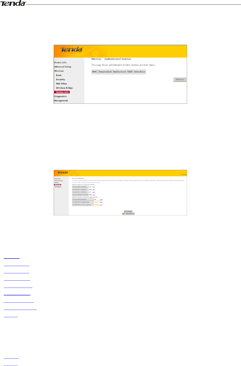
4.3.5 Station Info
This page shows authenticated wireless stations and their status.
4.4 Diagnostics
The modem router is capable of testing the connection to your DSL service provider, the connection to your Internet
service provider and the connection to your local network. If a test displays a fail status, click "Rerun Diagnostic Tests"
at the bottom of this page to make sure the fail status is consistent. If the test continues to fail, click "Help" and follow
the troubleshooting procedures.
4.5 Management
This section explains the following information:
• Settings
• System Logs
• Security Log
• SNMP Agent
• TR-069 Client
• Internet Time
• Access Control
• Update Software
• Reboot
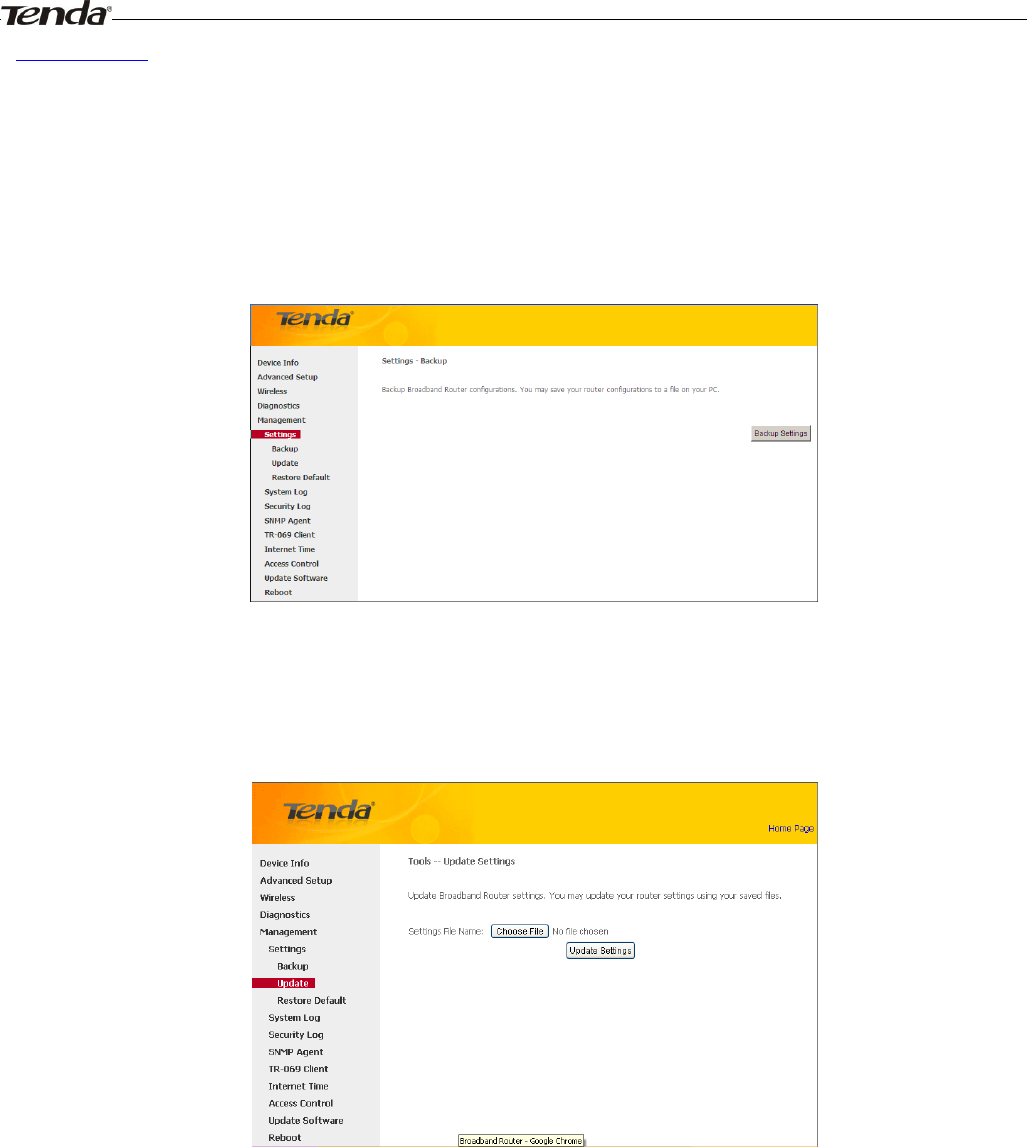
4.5.1 Settings
This section explains the following information:
• Backup
• Update
Wireless Modem Router User Guide
- 77 -
• Restore Default
Backup
Here you can save a copy of your device’s configurations to your computer. Once you have configured the device, you
can save these settings to a configuration file on your local hard drive. The configuration file can later be imported to
your device in case the device is reset to factory default settings.
Update
Here you can restore the configuration from a file saved on your PC.
Restore Default
Under some circumstances (for example, join a different network or unfortunately forgetting the login password), you
may need to remove the existing configuration and restore the factory default settings.
Wireless Modem Router User Guide
- 78 -
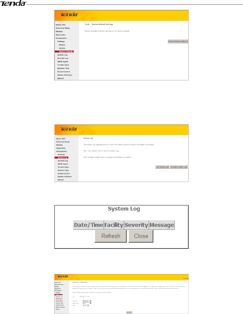
4.5.2 System Logs
The System Log dialog allows you to view the System Log and configure the System Log options.
To view the System Log, simply click View System Log.
To configure the System Log options, click Configure System Log.
Log: If Enable is selected, the system will begin to log all the selected events.
Log Level: All events above or equal to the selected level will be logged.
Display Level: All logged events above or equal to the selected level will be displayed.
Mode: If the selected mode is 'Remote' or 'Both,' events will be sent to the specified IP address and UDP port of the
remote syslog server. If the selected mode is 'Local' or 'Both,' events will be recorded in the local memory.
Wireless Modem Router User Guide
- 79 -
Server IP Address: Specify the IP address of the remote syslog server.
Server UDP Port: Specify the UDP port of the remote syslog server.
Apply/Save: click to apply and save the system log settings.
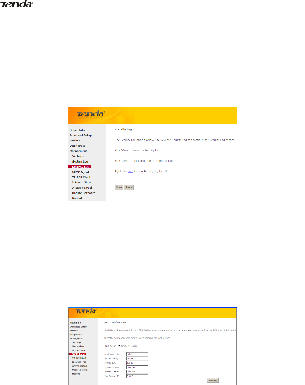
4.5.3 Security Log
The Security Log page allows you to view the Security Log and configure the Security Log options. You can also save
Security Log to a file.
View: Click to view the Security Log.
Reset: Click to clear and reset the Security Log.
4.5.4 SNMP Agent
Simple Network Management Protocol (SNMP) allows a management application to retrieve statistics and status from
the SNMP agent in this device.
SNMP Agent:Select “Enable” to activate the SNMP Agent feature or “Disable” to deactivate it.
Read Community: Specify a Read Community string. The default is public.
Set Community: Specify a Set Community string. The default is private.
System Name: Specify a descriptive system name.
System Location: Specify a system location.
System Contact: Specify a system contact.
Trap Manager IP: Specify the IP address of the Trap Manager.
Wireless Modem Router User Guide
- 80 -
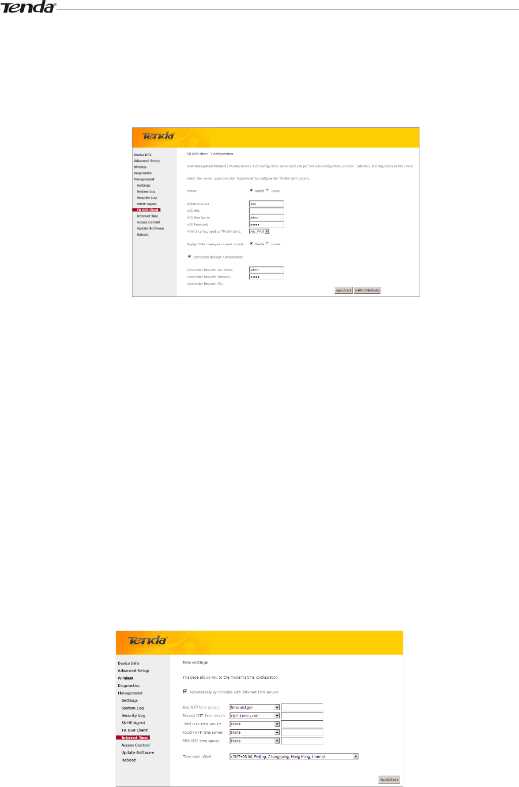
4.5.5 TR-069 Client
WAN Management Protocol (TR-069) allows a Auto-Configuration Server (ACS) to perform auto-configuration,
provision, collection, and diagnostics to this device.
Click the TR-069 Client tab to enter the TR-069 Client configuration screen as seen below:
Inform:Select Enable/Disable to enable/disable the TR-069 Client function. By default, it is disabled.
Inform Interval: Specify the inform interval.
ACS URL: Enter the ACS (Auto-Configuration Server) URL address.
ACS User Name: Enter the ACS (Auto-Configuration Server) user name.
ACS Password: Enter the ACS (Auto-Configuration Server) password.
WAN Interface used by TR-069 client: Select the WAN interface used by the TR-069 client from the drop-down list.
Display SOAP messages on serial console: If Enable is selected, SOAP messages will be displayed on serial console; if Disable is
selected, SOAP messages will not be displayed on serial console.
Connection Request Authentication: Check/uncheck to enable/disable the cnnection request authentication.
Connection Request User Name: Enter the cnnection request user name.
Connection Request Password: Enter the cnnection request password.
Connection Request URL: Specify the connection request URL.
4.5.6 Internet Time
This page is used to set the router’s system time. If Automatically synchronize with Internet time servers is checked, the system
will automatically connect to NTP server to synchronize the time.
Wireless Modem Router User Guide
- 81 -
First/Second/Third/Fourth/Fifth NTP time server: Select a NTP time server from the drop-down list. If the NTP time
server you are looking for is not included in the list, select “Other” and then enter it manually in the box.
Time zone offset: Select your time zone from the drop-down list.
4.5.7 Access Control
This section explains the following information:
• Password
• AccessControl - Service
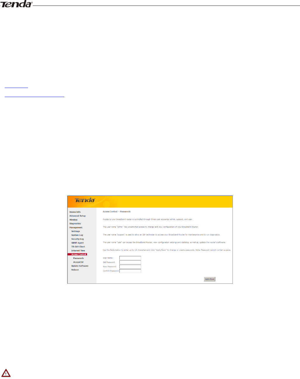
Password
Access to your broadband router is controlled through three user accounts: admin, support, and user.
The user name "admin" has unrestricted access to change and view configuration of your Broadband Router.
The user name "support" is used to allow an ISP technician to access your Broadband Router for maintenance and to run
diagnostics.
The user name "user" can access the Broadband Router, view configuration settings and statistics, as well as, update the
router's software.
User Name: Enter the user name of up to 16 characters.
Old Password: Enter the old password of up to 16 characters.
New Password: Enter a new password of up to 16 characters.
Confirm Password: Re-enter to confirm the new password.
Apply/Save: Click to change or create passwords.
_________________________________________________________________________________________________
Note:
Password cannot contain a space.
_________________________________________________________________________________________________
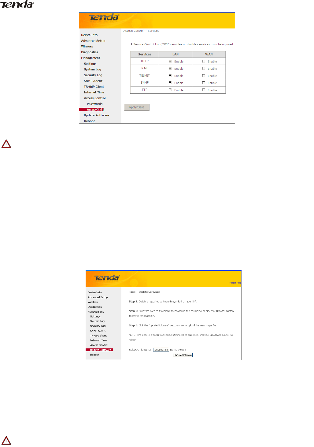
AccessControl - Service
Here you can manage the device either from LAN or WAN side using HTTP, ICMP, TELNET, SNMP and FTP.
Wireless Modem Router User Guide
- 82 -
_________________________________________________________________________________________________
Note:
1. If you are not an advanced user, we suggest you keep the default settings.
2. To access the device from the LAN side, you must use the LAN IP address and log in as "admin" or "user"; to access
the device from the WAN side, you must use the WAN IP address and log in as "support".
_________________________________________________________________________________________________
4.5.8 Update Software
Firmware upgrade is released periodically to improve the functionality of your device and add any new features. If you
run into a problem with a specific feature of the device you could log in to our website (www.tendacn.com) to download
the latest firmware to update your device.
To update software, do as follows:
1. Obtain an updated software image file from our website: www.tendacn.com.
2. Enter the path to the image file location in the box below or click the "Browse" button to locate the image file.
3. Click the "Update Software" button once to upload the new image file.
_________________________________________________________________________________________________
Note:
The update process takes about 2 minutes to complete, and your Broadband Router will reboot.
_________________________________________________________________________________________________
Wireless Modem Router User Guide
- 83 -
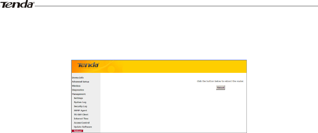
4.5.9 Reboot
Click the Reboot button to reboot the router.
Wireless Modem Router User Guide
- 84 -
Appendix 1 Configure Your PC
Screens to configure TCP/IP properties in other Operating Systems are similar to those below.
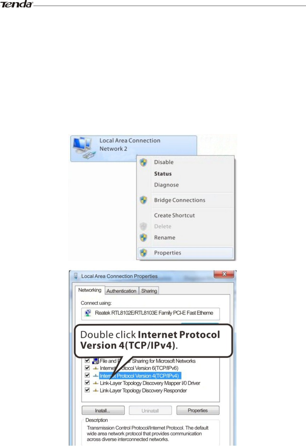
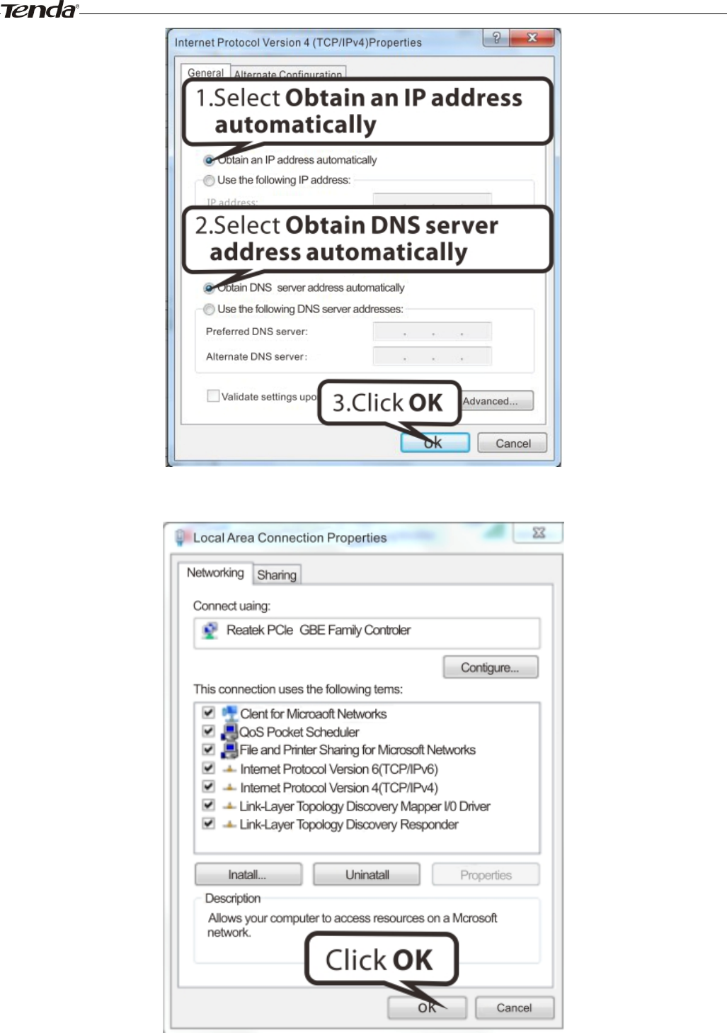
Windows 7
Click Start-> Control Panel-> Network and Sharing Center-> Change adapter settings, select a desired Local Area
Connection and select Properties.
Wireless Modem Router User Guide
- 85 -
Wireless Modem Router User Guide
- 86 -
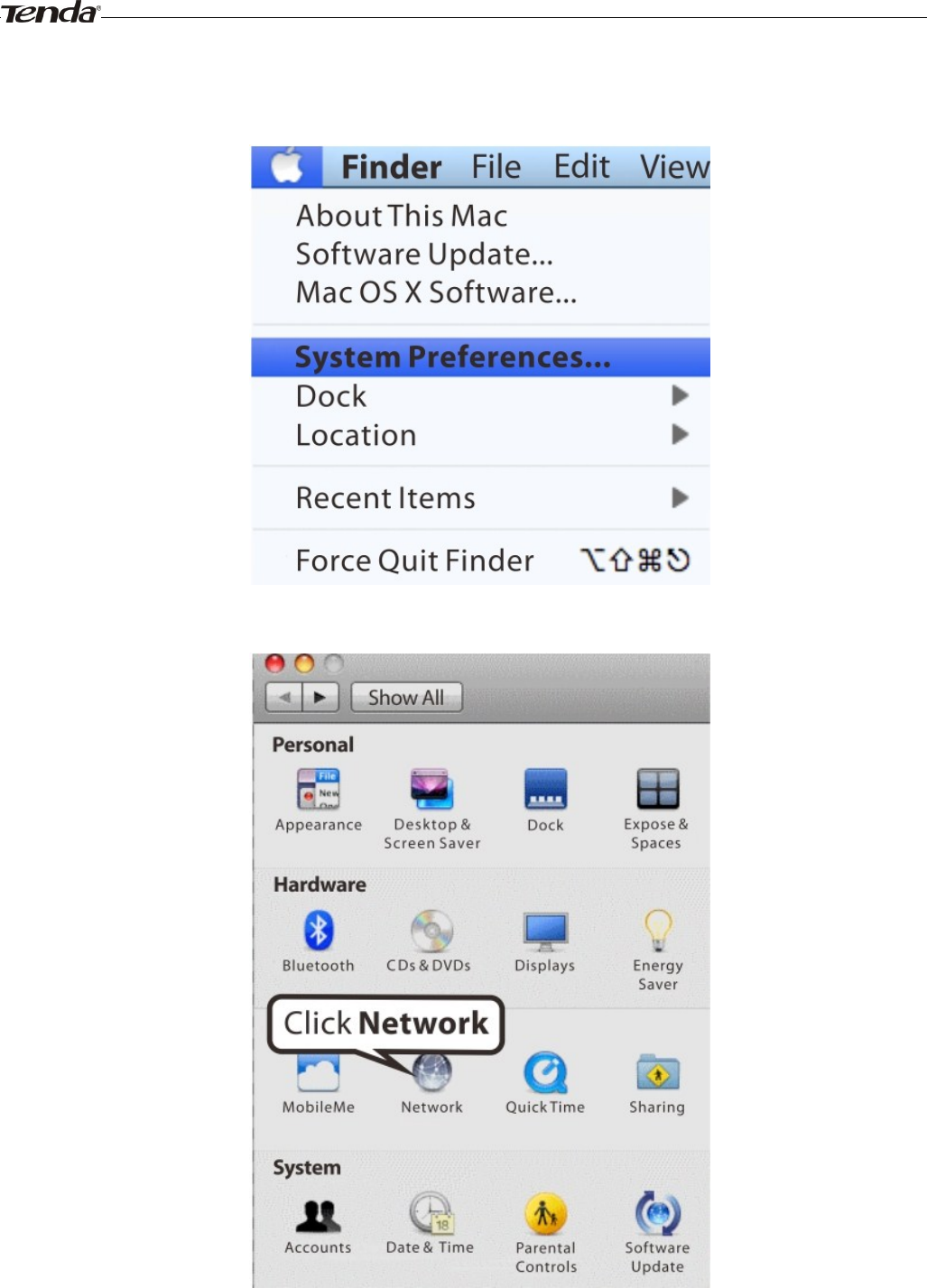
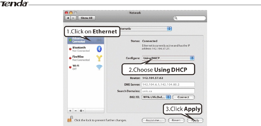
MAC
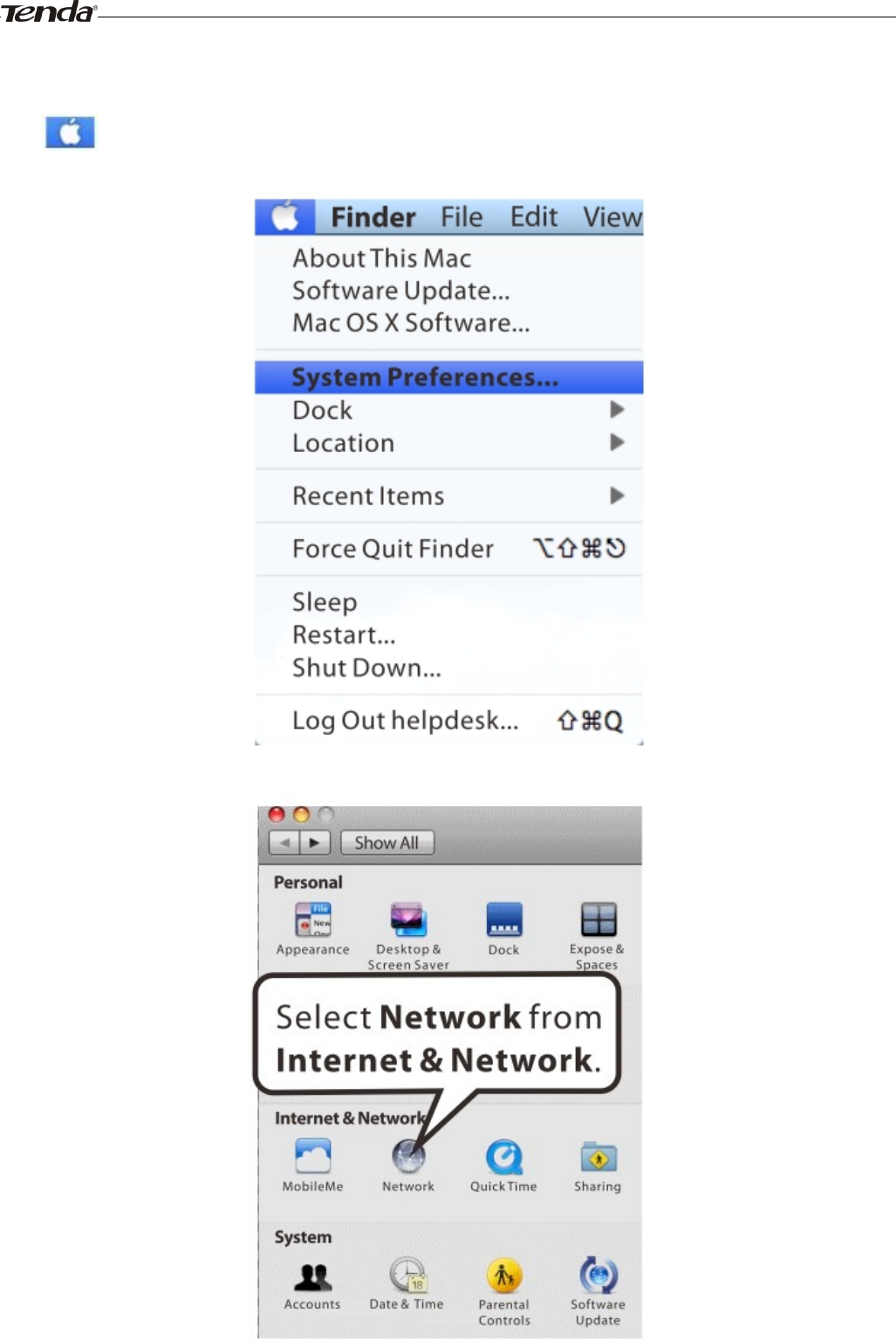
Click on the Apple icon from the top-left corner and select System Preferences.
Wireless Modem Router User Guide
- 87 -
Wireless Modem Router User Guide
- 88 -
Appendix 2 Join Your Wireless Network
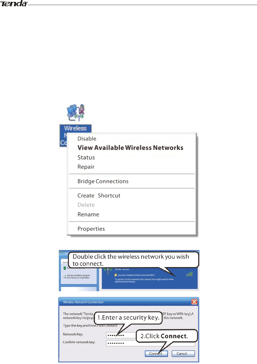
Windows XP
a). Click Start-> Settings -> Control Panel;
b). Double click Network Connections, select the desired wireless network connection and then click View Available
Wireless Networks.
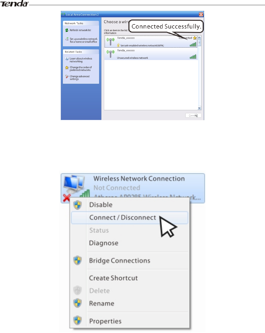
When you see Connected displayed next to the wireless network you selected, you have connected to the wireless
network successfully.
Wireless Modem Router User Guide
- 89 -
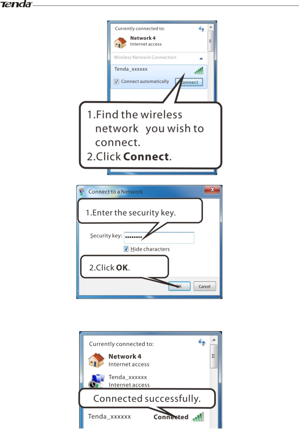
Windows 7
Click Start-> Control Panel-> Network and Sharing Center-> Change adapter settings, select a desired wireless
connection and click Connect/Disconnect.
Wireless Modem Router User Guide
- 90 -
When you see Connected displayed next to the wireless network you selected, you have connected to the wireless
network successfully.
Wireless Modem Router User Guide
- 91 -
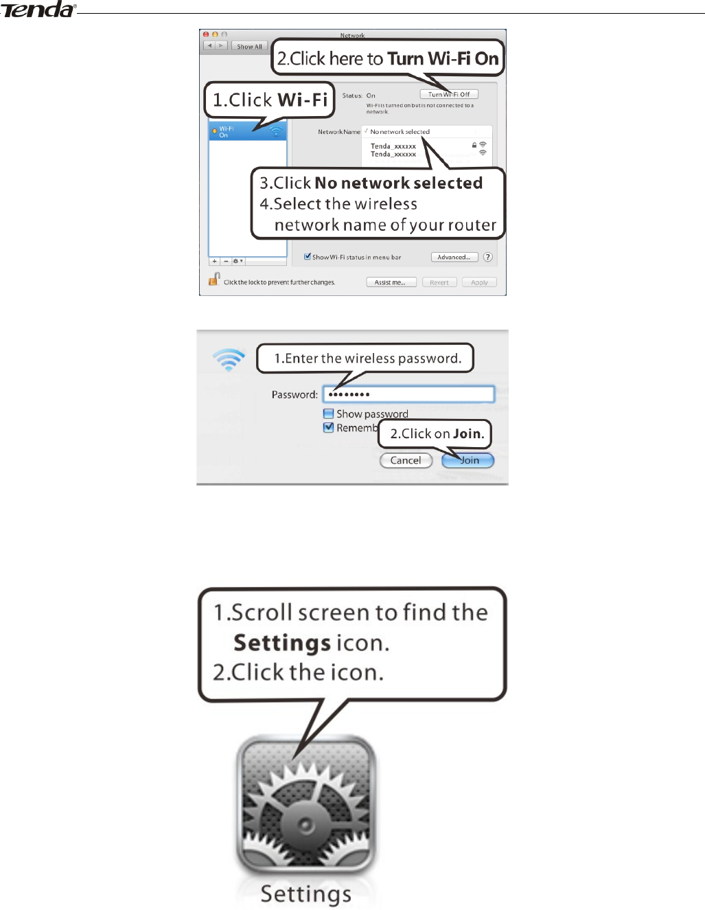
MAC
Click ->System Preferences.
Wireless Modem Router User Guide
- 92 -
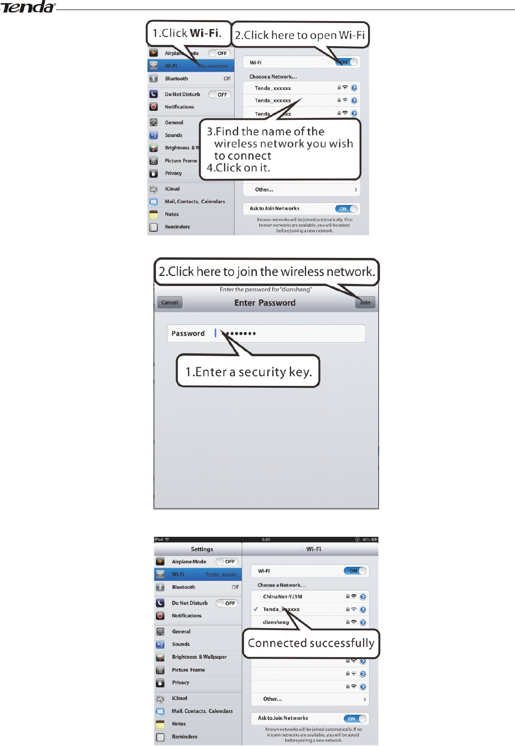
iPhone/iPad
Wireless Modem Router User Guide
- 93 -

Wireless Modem Router User Guide
- 94 -
Appendix 3 FAQs
1. What information should I have to access Internet via the ADSL uplink?
If you have DSL broadband service, you might need the following information to set up your modem router.
• Active Internet service provided by an ADSL account
• The ISP configuration information for your DSL account
- ISP login name and password
- Fixed or static IP address
Depending on how your ISP set up your Internet account, you could need to know the Virtual path identifier (VPI) and
virtual channel identifier (VCI) parameters for a manual setup.
2. I cannot access the device's management interface. What should I do?
1. Verify the physical connection (namely, the Ethernet cable) between your PC and the device. For details, see
Hardware Install hereof.
2. Double check the TCP/IP settings on your PC. For details, see Appendix 1.Configure PC hereof.
3. Press the Reset button on the device and then re-access the management interface.
4. Change the Ethernet cable that connects your PC and the device.
5. Try accessing device management interface from other PCs, smart phones or iPads.
6. Connect your PC alone to one of the LAN ports on the device.
3. I forget the wireless security key. What should I do? (How do I configure or change the security
key?)
1. Try the default security key, which can be seen from the label attached to the device bottom.
2. If step 1 that works, access the device web manager and customize a new security key.
3. If step 1 does not work, press the Reset button on the device to restore factory default settings. And then log in to
the device web manager to customize a new security key.
4. My notebook is unable to search wireless networks, what should I do?
1. Verify that wireless service is enabled on your notebook by checking the wireless hardware or software button on
your notebook. The hardware button is usually located on the side of your notebook. Note that some notebooks
may not have such hardware button. Software button can be implemented by pressing Fn+ . Fn is situated on
the bottom left corner of your keyboard, may be any key between F1-F12 depending on what type of
keyboard you are using.
2. Log in to the device, select Advanced-> Wireless-> Basic and change the wireless network name (SSID). Then
search again.
3. Follow below steps to verify that wireless service is enabled on your notebook (for Windows XP OS only).
From the desktop, right-click on the My Computer icon and select Manage. Select Services and Applications, double
click Services and view the status of Wireless Zero Configuration. If Status dose not display Started, right click the
Wireless Zero Configuration and select Start; if Startup Type displays Disabled, right click the Wireless Zero
Configuration, select Properties; from the Startup Type drop-down list box, select Automatic and then click Start in
Service Status.
5. Why cannot I connect to the searched wireless network?
1. Verify that you entered a correct security key.
2. Log in to the device, select Advanced-> Wireless and change the wireless network name (SSID). Then connect
again.

Wireless Modem Router User Guide
- 95 -
3. Log in to the device, select Advanced-> Wireless-> Security and change the security settings. Then connect again.
6. Where should I place the wireless device for optimum performance?
1. Place it in the center to extend wireless coverage as far as possible.
2. Never place the device near to metal objects or in direct sunshine.
3. Keep it far away from devices that use the 2.4 GHz radio wave frequency to transmit and receive data, such as
802.11g/n wireless network devices, electronic devices such as cell phones, radio transmitters, blue tooth, cordless
phones, fax machine, refrigerator and microwaves to avoid electronic interference.

Wireless Modem Router User Guide
- 96 -
Appendix 4 VPI/VCI List
The following table lists common ISPs and their VPI and VCI numbers. If you cannot locate your ISP and their VPI and
VCI information here, ask your ISP to provide it.
Country
ISP
VPI
VCI
Encapsulation
Australia
Telstra
8
35
PPPoA LLC
Australia
GoldenIT
8
35
_PPPOA_VCMUX
Australia
Telstra Bigpond
8
35
PPPOE_LLC
Australia
OptusNET
8
35
PPPOE_VCMUX
Australia
AAPT
8
35
PPPOE_VCMUX
Australia
ADSL Direct
8
35
PPPOE_LLC
Australia
Ausie Broadband
8
35
PPPOE_LLC
Australia
Australia On Line
8
35
PPPOA_VCMUX
Australia
Connexus
8
35
PPPOE_LLC
Australia
Dodo
8
35
PPPOE_LLC
Australia
Gotalk
8
35
PPPOE_VCMUX
Australia
Internode
8
35
PPPOE_VCMUX
Australia
iPrimus
8
35
PPPOA_VCMUX
Australia
Netspace
8
35
PPPOE_VCMUX
Australia
Southern Cross Telco
8
35
PPPOE_LLC
Australia
TPG Internet
8
35
PPPOE_LLC
Argentina
Telecom
0
33
PPPoE LLC
Argentina
Telefonica
8
35
PPPoE LLC
Argentina
1
33
PPPoA VC-MUX
Belgium
ADSL Office
8
35
1483 Routed IP LLC
Belgium
Turboline
8
35
PPPoA LLC
Bolivia
0
34
1483 Routed IP LLC
Brazil
Brasil Telcom
0
35
PPPoE LLC
Brazil
Telefonica
8
35
PPPoE LLC
Brazil
Telmar
0
33
PPPoE LLC
Brazil
South Region
1
32
PPPoE LLC
Colombia
EMCALI
0
33
PPPoA VC-MUX
Columbia
ETB
0
33
PPPoE LLC
Costa Rica
ICE
1
50
1483 Routed IP LLC
Denmark
Cybercity, Tiscali
0
35
PPPoA VC-MUX
France (1)
Orange
8
35
PPPoE LLC
France (2)
8
67
PPPoE LLC
France (3)
SFR
8
35
PPPoA VC-MUX
Germany
1
32
PPPoE LLC
Hungary
Sci-Network
0
35
PPPoE LLC
Iceland
Islandssimi
0
35
PPPoA VC-MUX

Wireless Modem Router User Guide
- 97 -
Iceland
Siminn
8
48
PPPoA VC-MUX
Israel
8
35
PPPoA VC-MUX
Italy
8
35
PPPoA VC-MUX
Iran (1)
0
35
PPPoE LLC
Iran (2)
8
81
PPPoE LLC
Israel(1)
8
48
PPPoA VC-MUX
Jamaica (1)
8
35
PPPoA VC-MUX
Jamaica (2)
0
35
PPPoA VC-MUX
Jamaica (3)
8
35
1483 Bridged IP LLC SNAP
Jamaica (4)
0
35
1483 Bridged IP LLC SNAP
Kazakhstan
0
33
PPPoA VC-MUX
Malaysia
0
35
PPPoE LLC
Mexico
Telmex (1)
8
81
PPPoE LLC
Mexico
Telmex (2)
8
35
PPPoE LLC
Mexico
Telmex (3)
0
81
PPPoE LLC
Mexico
Telmex (4)
0
35
PPPoE LLC
Netherlands
BBNED
0
35
PPPoA VC-MUX
Netherlands
MX Stream
8
48
PPPoA VC-MUX
New Zealand
Xtra
0
35
PPPoA VC-MUX
New Zealand
Slingshot
0
100
PPPoA VC-MUX
Pakistan (cyber net)
8
35
PPPoE LLC
Pakistan (linkDotnet)
0
35
PPPoA LLC
Pakistan(PTCL)
8
81
PPPoE LLc
Portugal
0
35
PPPoE LLC
Puerto Rico
Coqui.net
0
35
PPPoA LLC
Saudi Arabia (1)
0
33
PPPoE LLC
Saudi Arabia (2)
0
35
PPPoE LLC
Saudi Arabia (3)
0
33
1483 Bridged IP LLC
Saudi Arabia (4)
0
33
1483 Routed IP LLC
Saudi Arabia (5)
0
35
1483 Bridged IP LLC
Saudi Arabia (6)
0
35
1483 Routed IP LLC
Spain
Albura, Tiscali
1
32
PPPoA VC-MUX
Spain
Colt Telecom, Ola
Internet
0
35
PPPoA VC-MUX
Spain
EresMas, Retevision
8
35
PPPoA VC-MUX
Spain
Telefonica (1)
8
32
PPPoE LLC
Spain
Telefonica (2), Terra
8
32
1483 Routed IP LLC
Spain
Wanadoo (1)
8
35
PPPoA VC-MUX
Spain
Wanadoo (2)
8
32
PPPoE LLC
Spain
Wanadoo (3)
8
32
1483 Routed IP LLC
Sweden
Telenordia
8
35
PPPoE
Sweden
Telia
8
35
1483 Routed IP LLC
Switzerland
8
35
PPPoE LLC
Trinidad & Tobago
TSTT
0
35
PPPoA VC-MUX
Turkey (1)
8
35
PPPoE LLC

Wireless Modem Router User Guide
- 98 -
Turkey (2)
8
35
PPPoA VC-MUX
Thailand
TRUE
0
100
PPPoE LLC
Thailand
TOT
1
32
PPPoE LLC
Thailand
3BB
0
33
PPPoE LLC
Thailand
Cat Telecom
0
35
PPPoE LLC
Thailand
BuddyBB
0
35
PPPoE LLC
United States
4DV.Net
0
32
PPPoA VC-MUX
United States
All Tel (1)
0
35
PPPoE LLC
United States
All Tel (2)
0
35
1483 Bridged IP LLC
United States
Ameritech
8
35
PPPoA LLC
United States
AT&T (1)
0
35
PPPoE LLC
United States
AT&T (2)
8
35
1483 Bridged IP LLC
United States
AT&T (3)
0
35
1483 Bridged IP LLC
United States
August.net (1)
0
35
1483 Bridged IP LLC
United States
August.net (2)
8
35
1483 Bridged IP LLC
United States
BellSouth
8
35
PPPoE LLC
United States
Casstle.Net
0
96
1483 Bridged IP LLC
United States
CenturyTel (1)
8
35
PPPoE LLC
United States
CenturyTel (2)
8
35
1483 Bridged IP LLC
United States
Coqui.net
0
35
PPPoA LLC
United States
Covad
0
35
PPPoE LLC
United States
Earthlink (1)
0
35
PPPoE LLC
United States
Earthlink (2)
8
35
PPPoE LLC
United States
Earthlink (3)
8
35
PPPoE VC-MUX
United States
Earthlink (4)
0
32
PPPoA LLC
United States
Eastex
0
100
PPPoA LLC
United States
Embarq
8
35
1483 Bridged IP LLC
United States
Frontier
0
35
PPPoE LLC
United States
Grande ommunications
1
34
PPPoE LLC
United States
GWI
0
35
1483 Bridged IP LLC
United States
Hotwire
0
35
1483 Bridged IP LLC
United States
Internet Junction
0
35
1484 Bridged IP LLC
United States
PVT
0
35
1485 Bridged IP LLC
United States
QWest (1)
0
32
PPPoALLC
United States
QWest (2)
0
32
PPPoA VC-MUX
United States
QWest (3)
0
32
1483 Bridged IP LLC
United States
QWest (4)
0
32
PPPoE LLC
United States
SBC (1)
0
35
PPPoE LLC
United States
SBC (2)
0
35
1483 Bridged IP LLC
United States
SBC (3)
8
35
1483 Bridged IP LLC
United States
Sonic
0
35
1484 Bridged IP LLC
United States
SouthWestern Bell
0
35
1483 Bridged IP LLC
United States
Sprint (1)
0
35
PPPoALLC
United States
Sprint (2)
8
35
PPPoE LLC

Wireless Modem Router User Guide
- 99 -
United States
Sprint Territory
0
35
PPPoE LLC
United States
SureWest
Communications(1)
0
34
1483 Bridged LLC Snap
United States
SureWest
Communications(2)
0
32
PPPoE LLC
United States
SureWest
Communications(3)
0
32
PPPoA LLC
United States
Toast.Net
0
35
PPPoE LLC
United States
Uniserv
0
33
1483 Bridged IP LLC
United States
US West
0
32
PPPoA VC-MUX
United States
Verizon (1)
0
35
PPPoE LLC
United States
Verizon (2)
0
35
1483 Bridged IP LLC
United States
Windstream
0
35
PPPoE LLC
Canada
Primus Canada
0
35
PPPoE LLC
Canada
Rogers Canada (1)
0
35
PPPoE LLC
Canada
Rogers Canada (2)
8
35
1483 Bridged IP LLC
Canada
Rogers Canada (3)
0
35
1484 Bridged IP LLC
Canada
BellSouth(1) Canada
8
35
PPPoE LLC
Canada
BellSouth(2) Canada
0
35
PPPoE LLC
Canada
Sprint (1) Canada
0
35
PPPoA LLC
Canada
Sprint (2) Canada
8
35
PPPoE LLC
Canada
Verizon (1) Canada
0
35
PPPoE LLC
Canada
Verizon (2) Canada
0
35
1483 Bridged IP LLC
United States
Verizon (2)
0
35
1483 Bridged IP LLC
United Kingdom (1)
0
38
PPPoA VC-MUX
United Kingdom (2)
0
38
PPPoE LLC
United Kingdom
AOL
0
38
PPPoE VC-MUX
United Kingdom
Karoo
1
50
PPPoA LLC
Venezuela
CANTV
0
33
1483 Routed IP LLC
Vietnam
0
35
PPPoE LLC
Vietnam
VDC
8
35
PPPoE LLC
Vietnam
Viettel
8
35
PPPoE LLC
Vietnam
FPT
0
33
PPPoE LLC
Russia
Rostel
0
35
PPPoE LLC
Russia
Port telecom
0
35
PPPoE LLC
Russia
VNTC
8
35
PPPoE LLC
Uzbekistan
Sharq Stream
8
35
PPPoE LLC
Uzbekistan
Sarkor
0
33
PPPoE LLC
Uzbekistan
TShTT
0
35
PPPoE LLC
Kazakhstan
Kazakhtelecom
«Megaline»
0
40
LLC/SNAP Bridging
Spain
Arrakis
0
35
1483 Bridged IP VC-MUX
Spain
Auna
8
35
1483 Bridged IP VC-MUX
Spain
Comunitel
0
33
1483 Bridged IP VC-MUX

Wireless Modem Router User Guide
- 100 -
Spain
Eresmas
8
35
1483 Bridged IP VC-MUX
Spain
Jazztel
8
35
IPOE VC-MUX
Spain
Jazztel ADSL2+ /
Desagregado
8
35
1483 Bridged IP
LLC-BRIDGING
Spain
OpenforYou
8
32
1483 Bridged IP VC-MUX
Spain
Tele2
8
35
1483 Bridged IP VC-MUX
Spain
Telefónica (España)
8
32
1483 Bridged IP LLC/SNAP
Telefónica
(Argentina)
8
35
1483 Bridged IP LLC-based
Telefónica (Perú)
8
48
1483 Bridged IP VC-MUX
Spain
Terra
8
32
1483 Bridged IP LLC/SNAP
Spain
Terra
8
32
1483 Bridged IP LLC/SNAP
Spain
Uni2
1
33
1483 Bridged IP VC-MUX
Spain
Orange
8
35
1483 Bridged IP VC-MUX
Spain
Orange 20 Megas
8
35
LLC-BRIDGING
Spain
Orange
8
32
1483 Bridged IP LLC/SNAP
Spain
Ya.com
8
32
1483 Bridged IP VC - MUX
Spain
Ya.com
8
32
1483 Bridged IP LLC/SNAP
France
Free
8
36
LLC
Netherlands
MXSTREAM
8
48
1483 Bridged IP LLC
Netherlands
BBNED
0
35
1483 Bridged IP LLC
Belgium
Turboline
8
35
1483 Bridged IP LLC
Belgium
ADSL Office
8
35
1483 Bridged IP LLC
UK
0
38
1483 Bridged IP LLC
Italy
8
35
1483 Bridged IP LLC
Switzerland
8
35
1483 Bridged IP LLC
SpainWanadoo
8
32
1483 Bridged IP LLC
Czech Republic
8
48
1483 Bridged IP LLC
Dubai
0
50
1483 Bridged IP LLC
UAE (Al sahmil)
0
50
1483 Bridged IP LLC
Egypt:
TE-data
0
35
1483 Bridged IP LLC
Egypt:
Linkdsl
0
35
1483 Bridged IP LLC
Egypt:
Vodafone
8
35
1483 Bridged IP LLC
kuwait unitednetwork
0
33
1483 Bridged IP LLC
Pakistan
(PALESTINE)
8
35
1483 Bridged IP LLC
Dominican Republic
0
33
1483 Bridged IP LLC
Orange Nyumbani
(Kenya)
0
35
PPPoE LLC
Pakistan for PTCL
0
103
1483 Bridged IP LLC
Sri Lanka
Telecom-(SLT)
8
35
PPPOE LLC
Philippines(1)
0
35
1483 Bridged IP LLC
Philippines(2)
0
100
1483 Bridged IP LLC
RomTelecom
Romania:
0
35
1483 Bridged IP LLC

Wireless Modem Router User Guide
- 101 -
Finland
Saunalahti 0 100 1483 Bridged IP LLC
Finland
Elisa 0 100 1483 Bridged IP LLC
Finland
DNA 0 100 1483 Bridged IP LLC
Finland
Sonera 0 35 1483 Bridged IP LLC
Iran
[Shatel]
Aria-Rasaneh-Tadbir 0 35 PPPOE LLC
Iran
Asia-Tech
0
35
PPPOE LLC
Iran
Pars-Online (Tehran) 0 35 PPPOE LLC
Iran
Pars-Online (Provinces) 0 59 PPPOE LLC
Iran
[Saba-Net]
Neda-Gostar-Saba 0 35 PPPOE LLC
Iran
Pishgaman-Tose 0 35 PPPOE LLC
Iran
Fan-Ava 8 35 PPPOE LLC
Iran
Datak 0 35 PPPOE LLC
Iran
Laser (General) 0 35 PPPOE LLC
Iran
Laser (Privates) 0 32 PPPOE LLC
Iran
Asr-Enteghal-Dadeha 8 35 PPPOE LLC
Iran
Kara-Amin-Ertebat 0 33 PPPOE LLC
Iran
ITC 0 35 PPPOE LLC
Iran
Dadegostar Asre Novin 0 33 PPPOE LLC
India
Airtel 1 32 1483 Bridged IP LLC
India
BSNL 0 35 1483 Bridged IP LLC
India
MTNL 0 35 1483 Bridged IP LLC
India
RELIANCE
COMMUNICATION 0 35 PPPOE LLC
India
TATA INDICOM 0 32 PPPOE LLC
India
CONNECT 1 32 PPPOE LLC
morocco
IAM 8 35 PPPOE
Malaysia
Streamyx 0 35 PPPOE LLC
Indonesia Speedy
Telkomnet
8 81 PPPoE LLC

Wireless Modem Router User Guide
- 102 -
Appendix 5 Regulatory Compliance Information
CE Mark Warning
This is a Class B product In a domestic environment,this product may cause radio interference,in which case the user
may be required to take adequate measures.This device complies with EU 1999/5/EC.
NOTE:(1)The manufacturer is not responsible for any radio or TV interference caused by unauthorized modifications to
this equipment.(2) To avoid unnecessary radiation interference, it is recommended to use a shielded RJ45 cable
FCC Statement
This device complies with Part 15 of the FCC Rules. Operation is subject to the following two conditions: (1) This
device may not cause harmful interference, and (2) this device must accept any interference received, including
interference that may cause undesired operation.
This equipment has been tested and found to comply with the limits for a Class B digital device, pursuant to Part 15 of
the FCC Rules. These limits are designed to provide reasonable protection against harmful interference in a residential
installation. This equipment generates, uses and can radiate radio frequency energy and, if not installed and used in
accordance with the instructions, may cause harmful interference to radio communications. However, there is no
guarantee that interference will not occur in a particular installation. If this equipment does cause harmful interference
to radio or television reception, which can be determined by turning the equipment off and on, the user is encouraged to
try to correct the interference by one of the following measures:
ȍ Reorient or relocate the receiving antenna.
ȍ Increase the separation between the equipment and receiver.
ȍ Connect the equipment into an outlet on a circuit different from that
to which the receiver is connected.
ȍ Consult the dealer or an experienced radio/TV technician for help.
FCC Caution: Any changes or modifications not expressly approved by the party responsible for compliance could void
the user's authority to operate this equipment.
This transmitter must not be co-located or operating in conjunction with any other antenna or transmitter.

Wireless Modem Router User Guide
- 103 -
The manufacturer is not responsible for any radio or TV interference caused by unauthorized modifications to this
equipment.
Radiation Exposure Statement
This equipment complies with FCC radiation exposure limits set forth for an uncontrolled environment. This equipment
should be installed and operated with minimum distance 20cm between the radiator & your body.
NOTE: (1)The manufacturer is not responsible for any radio or TV interference caused by unauthorized modifications to
this equipment.(2) To avoid unnecessary radiation interference, it is recommended to use a shielded RJ45 cable
IC RSS warning
This device complies with Industry Canada licence-exempt RSS standard (s). Operation is subject to the
following two conditions: (1) this device may not cause interference, and (2) this device must accept any
interference,including interference that may cause undesired operation of the device.
Le présent appareil est conforme aux CNR d'Industrie Canada applicables aux appareils radio exempts
de licence.
L'exploitation est autorisée aux deux conditions suivantes:
(1) l'appareil ne doit pas produire de brouillage, et
(2) l'utilisateur de l'appareil doit accepter tout brouillage radioélectrique subi, même si le brouillage est
susceptible d'en compromettre le fonctionnement.
Under Industry Canada regulations, this radio transmitter may only operate using an antenna of a type and
maximum (or lesser) gain approved for the transmitter by Industry Canada. To reduce potential radio
interference to other users, the antenna type and its gain should be so chosen that, the equivalent
isotropically radiated power (e.i.r.p.) is not more than that necessary for successful communication.
Conformément à la réglementation d'Industrie Canada, le présent émetteur radio peut fonctionner avec
une antenne d'un type et d'un gain maximal (ou inférieur) approuvé pour l'émetteur par Industrie Canada.
Dans le but de réduire les risques de brouillage radioélectrique à l'intention des autres utilisateurs, il faut
choisir le type d'antenne et son gain de sorte que la puissance isotrope rayonnée équivalente (p.i.r.e.) ne
dépasse pas l'intensité nécessaire à l'établissement d'une communication satisfaisante.
(1/2) This radio transmitter (identify the device by certification number, or model number if Category II)
has been approved by Industry Canada to operate with the antenna types listed below with the maximum
permissible gain and required antenna impedance for each antenna type indicated. Antenna types not
included in this list, having a gain greater than the maximum gain indicated for that type, are strictly
prohibited for use with this device.
Le présent émetteur radio (identifier le dispositif par son numéro de certification ou son numéro de
modèle s'il fait partie du matériel de catégorie I) a été approuvé par Industrie Canada pour fonctionner
avec les types d'antenne énumérés ci-dessous et ayant un gain admissible maximal etl'impédance requise
pour chaque type d'antenne. Les types d'antenne non inclus dans cette liste, ou dont le gain est supérieur
au gain maximal indiqué, sont strictement interdits pour l'exploitation de l'émetteur.
IC Radiation Exposure Statement:
This equipment complies with IC RF radiation exposure limits set forth for an uncontrolled environment.
This transmitter must not be co-located or operating in conjunction with any other antenna or transmitter.
This equipment should be installed and operated with minimum distance 20cm between the radiator & your body.