TENDA TECHNOLOGY D151 ADSL Router User Manual
SHENZHEN TENDA TECHNOLOGY CO., LTD. ADSL Router
UserManual.wiki
>
TENDA TECHNOLOGY
>
D151 User Manual
>
Users Manual Part 2
Contents
1.
Users Manual Part 1
2.
Users Manual Part 2
Users Manual Part 2
Navigation menu
Upload a User Manual
Namespaces
Wiki Guide
HTML
PDF
Info
Views
User Manual
Discussion / Help
Navigation
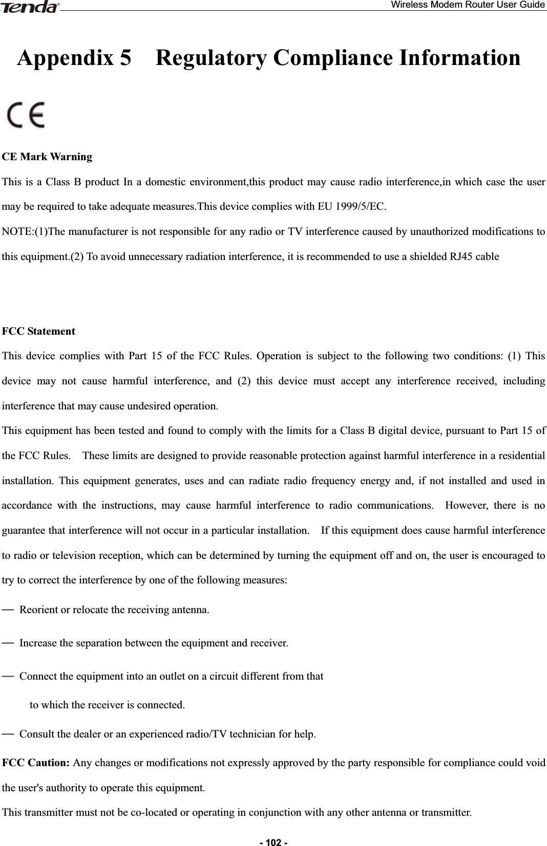
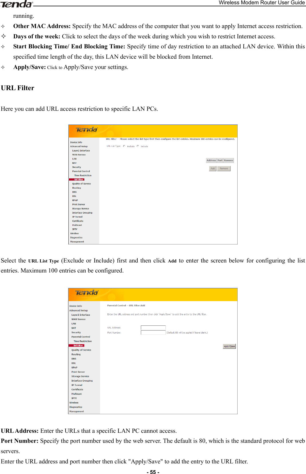
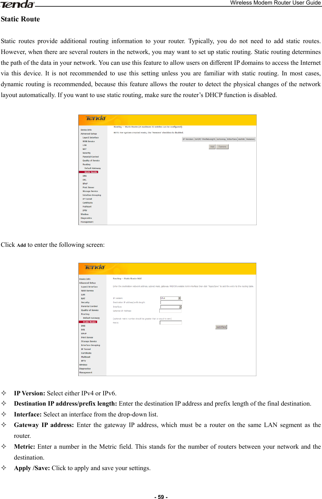
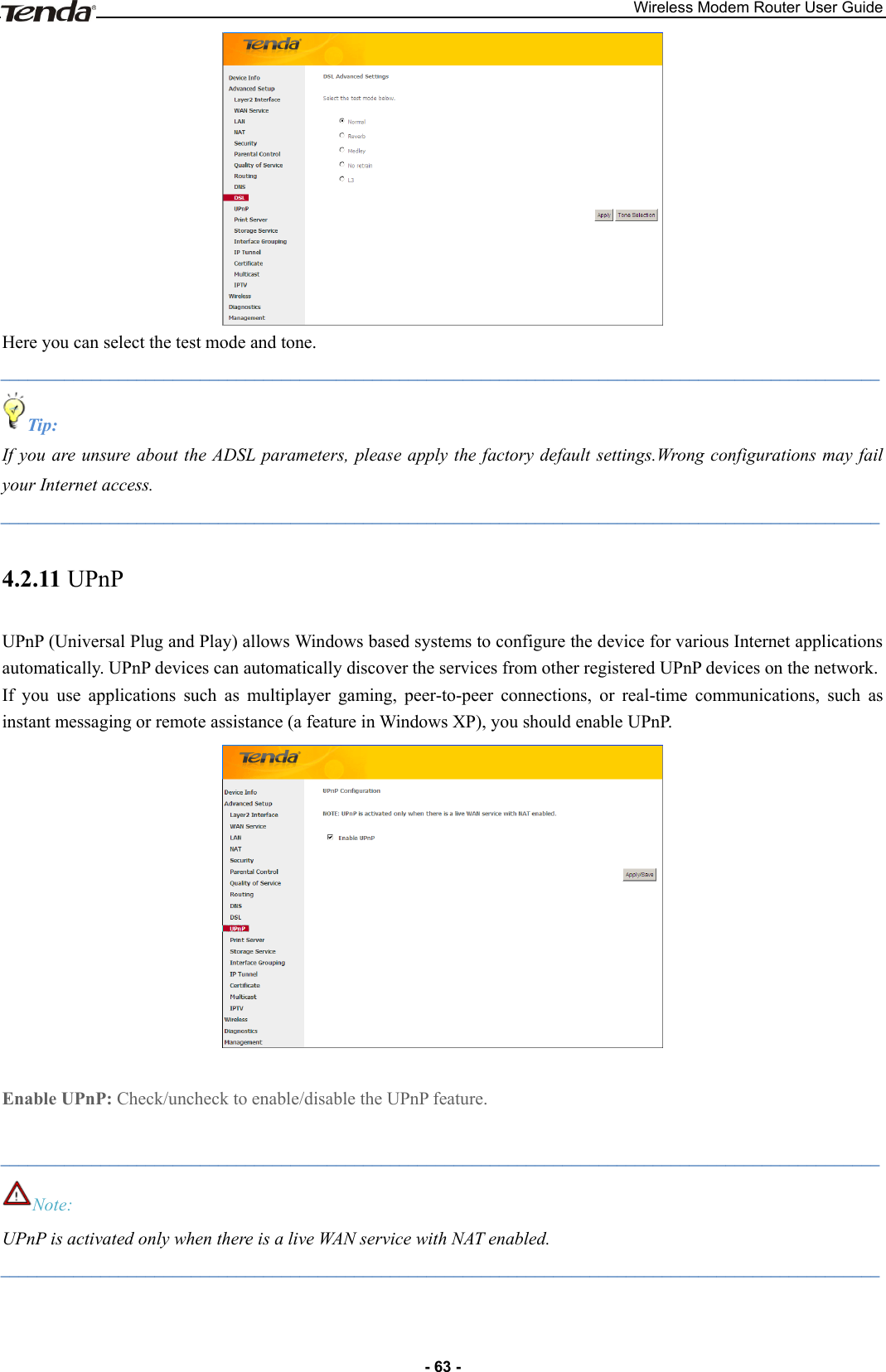
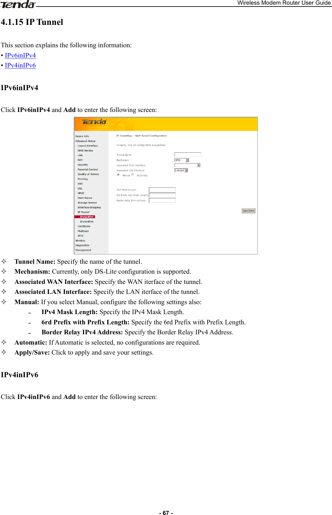
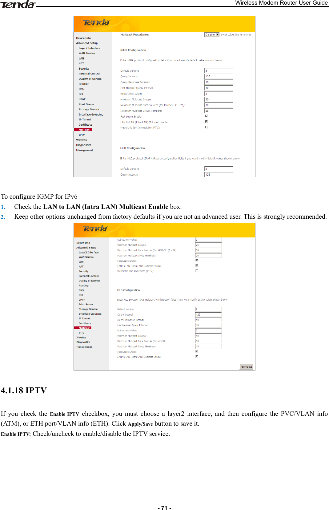
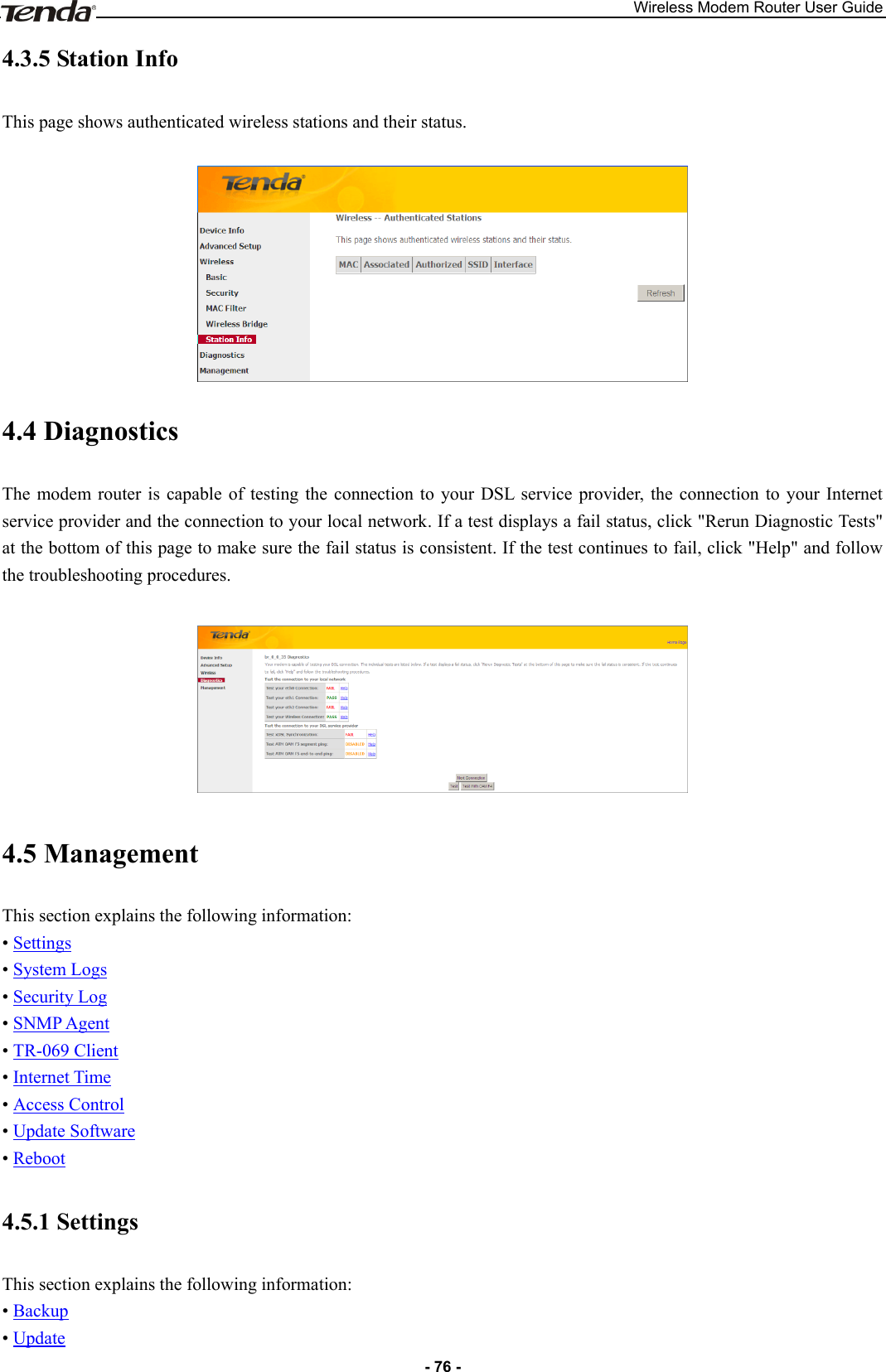
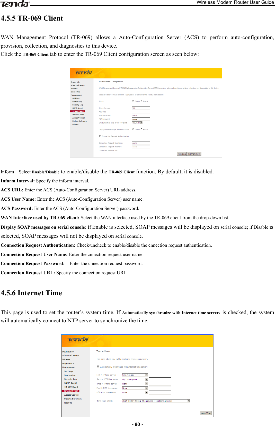
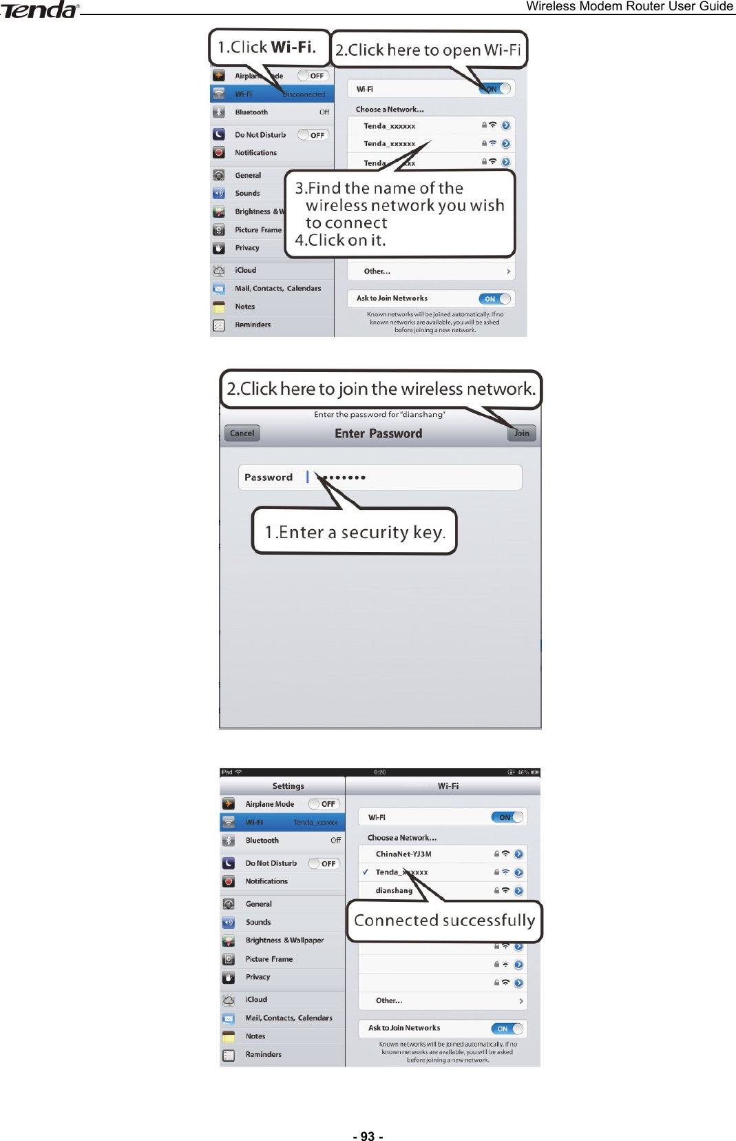
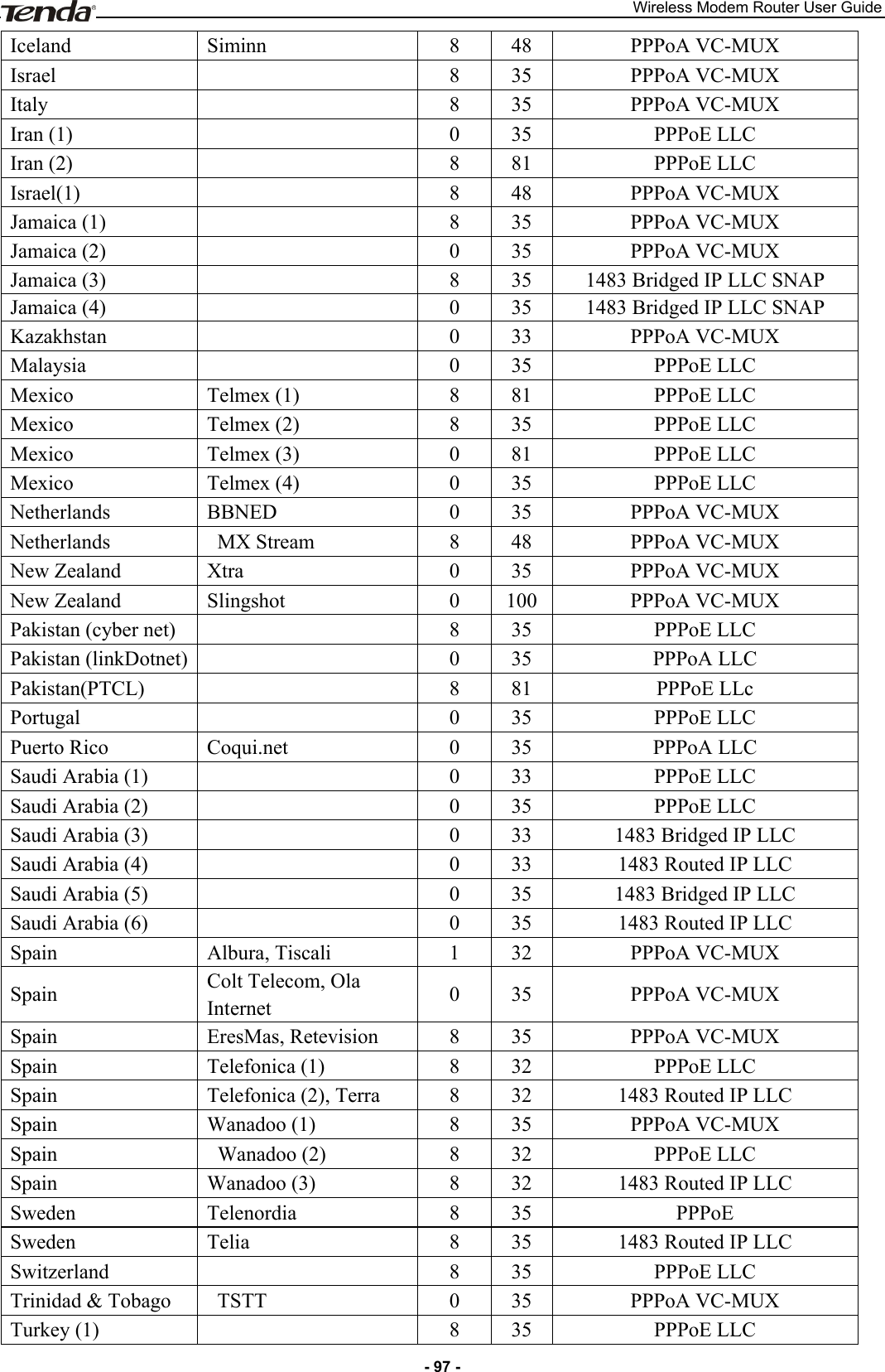
![Wireless Modem Router User Guide - 52 - This screen allows you to create a filter rule to identify outgoing IP traffic by specifying a new filter name and at least one condition below. All of the specified conditions in this filter rule must be satisfied for the rule to take effect. Click 'Apply/Save' to save and activate the filter. Filter Name: Enter a descriptive filtering name. IP Version: Select either IPv4 or IPv6. Protocol: TCP/UDP, TCP, UDP and ICMP are available for your option. Source IP address [/prefix length]: Enter the LAN IP address to be filtered. Source Port (port or port: port): Specify a port number or a range of ports used by LAN PCs to access Internet. If you are unsure, leave it blank. Destination IP address [/prefix length]: Specify the external network IP address to be accessed by specified LAN PCs. Destination Port (port or port:port): Specify a port number or a range of ports used by LAN PCs to access external network. Incoming IP Filtering Setup When the firewall is enabled on a WAN or LAN interface, all incoming IP traffic is BLOCKED. However, some IP traffic can be ACCEPTED by setting up filters. Choose Add or Remove to configure incoming IP filters. Click Add to enter the following screen:](https://usermanual.wiki/TENDA-TECHNOLOGY/D151.Users-Manual-Part-2/User-Guide-2092079-Page-2.png)
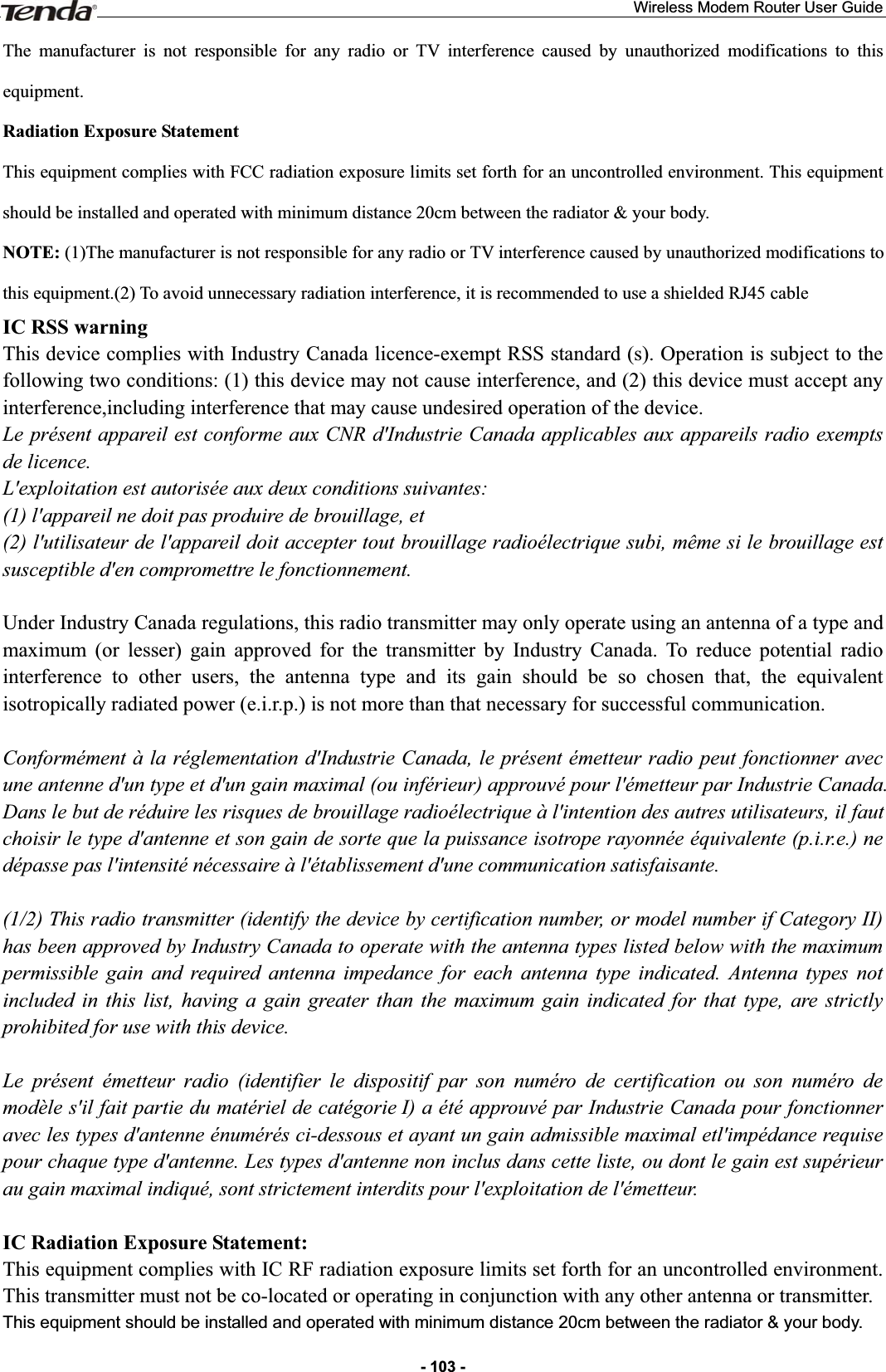
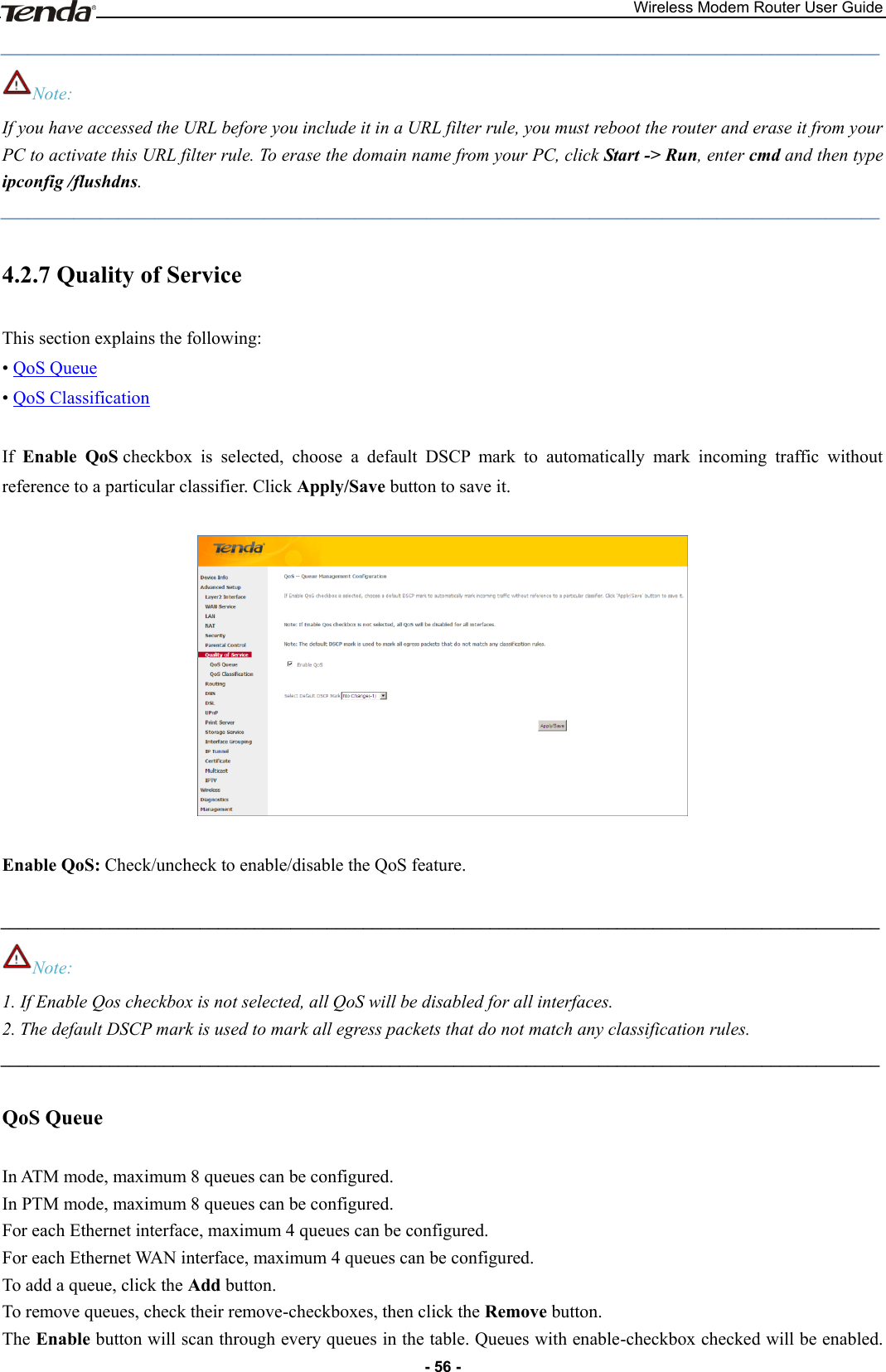
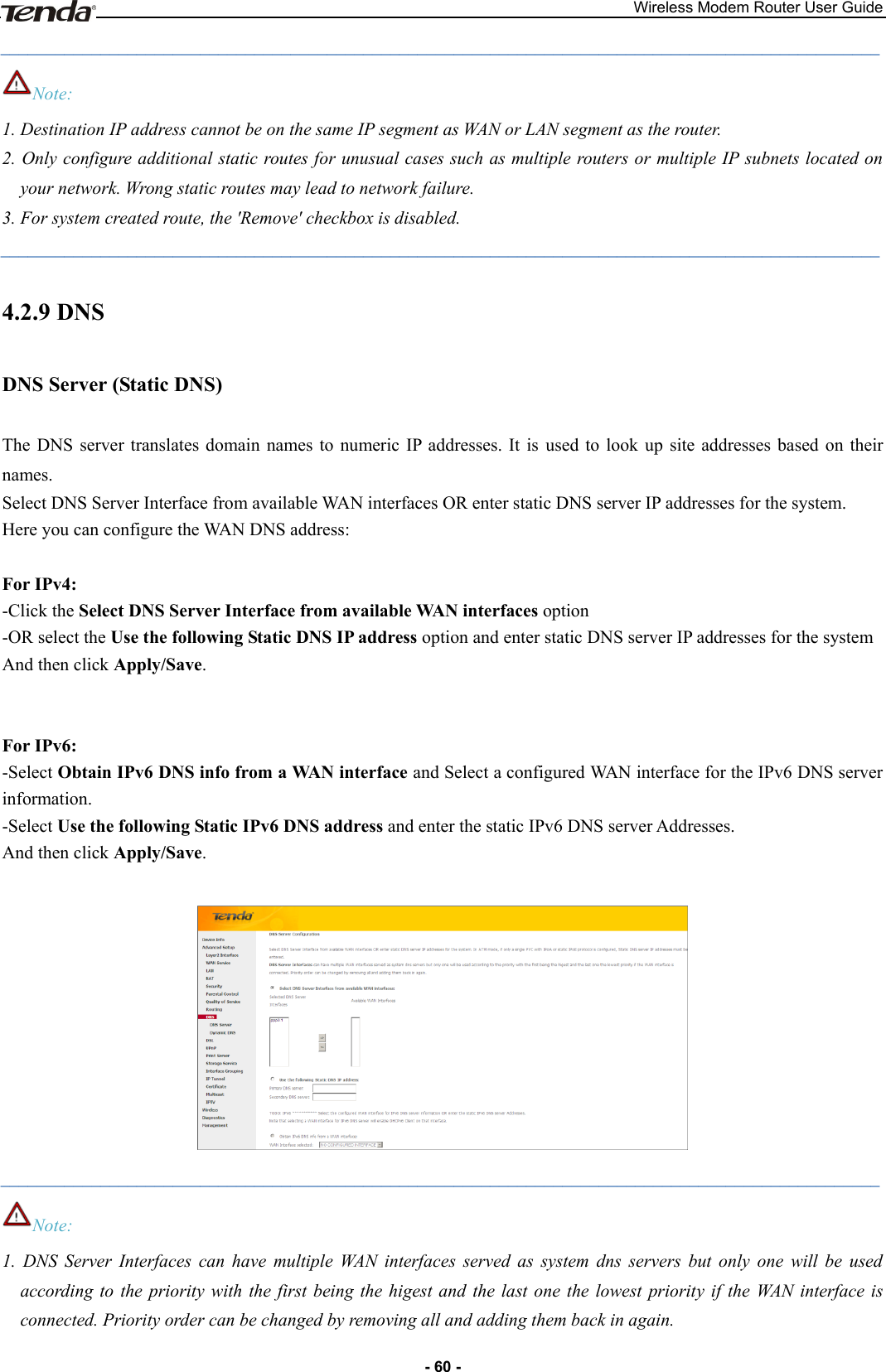
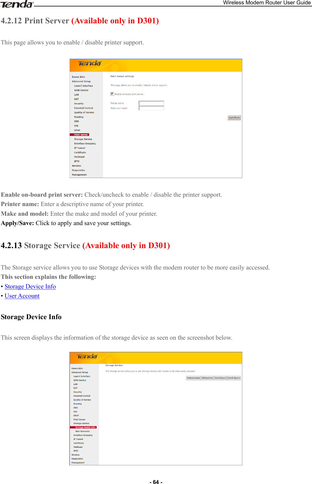
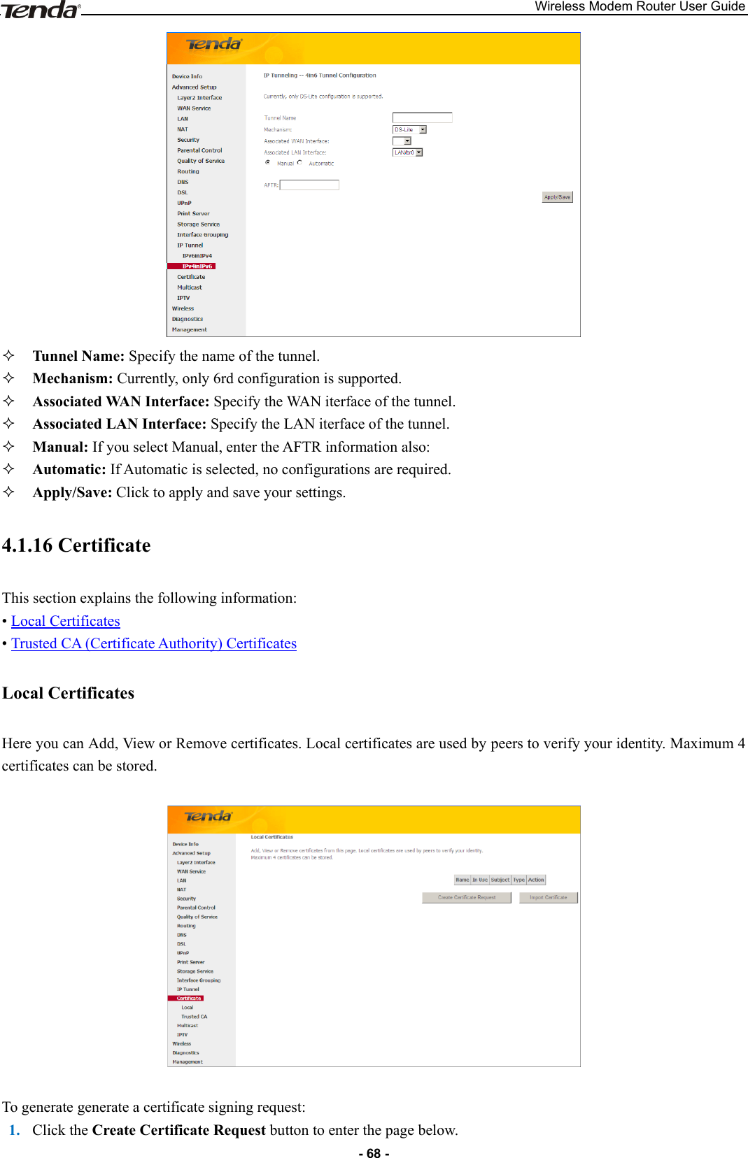
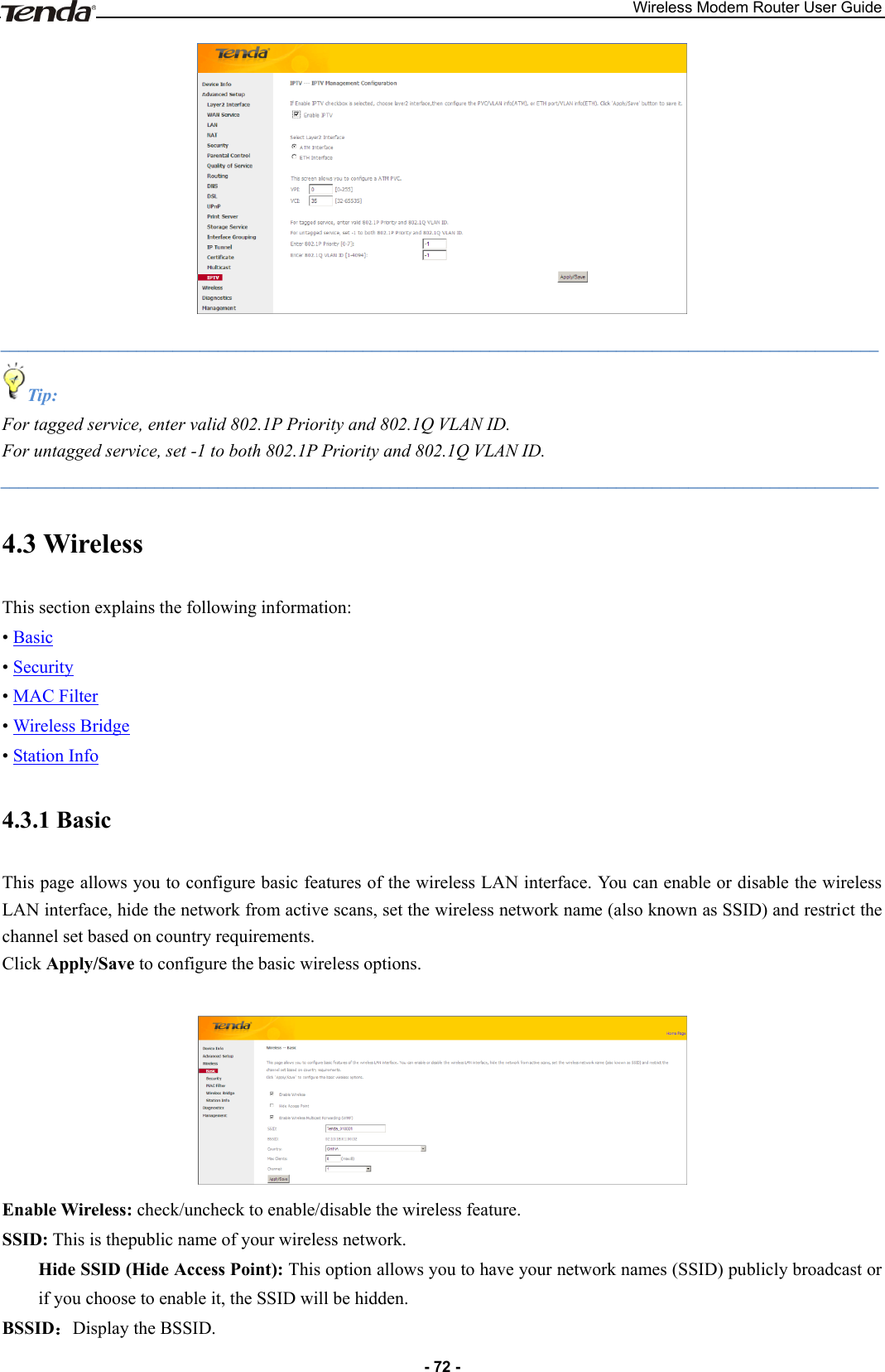
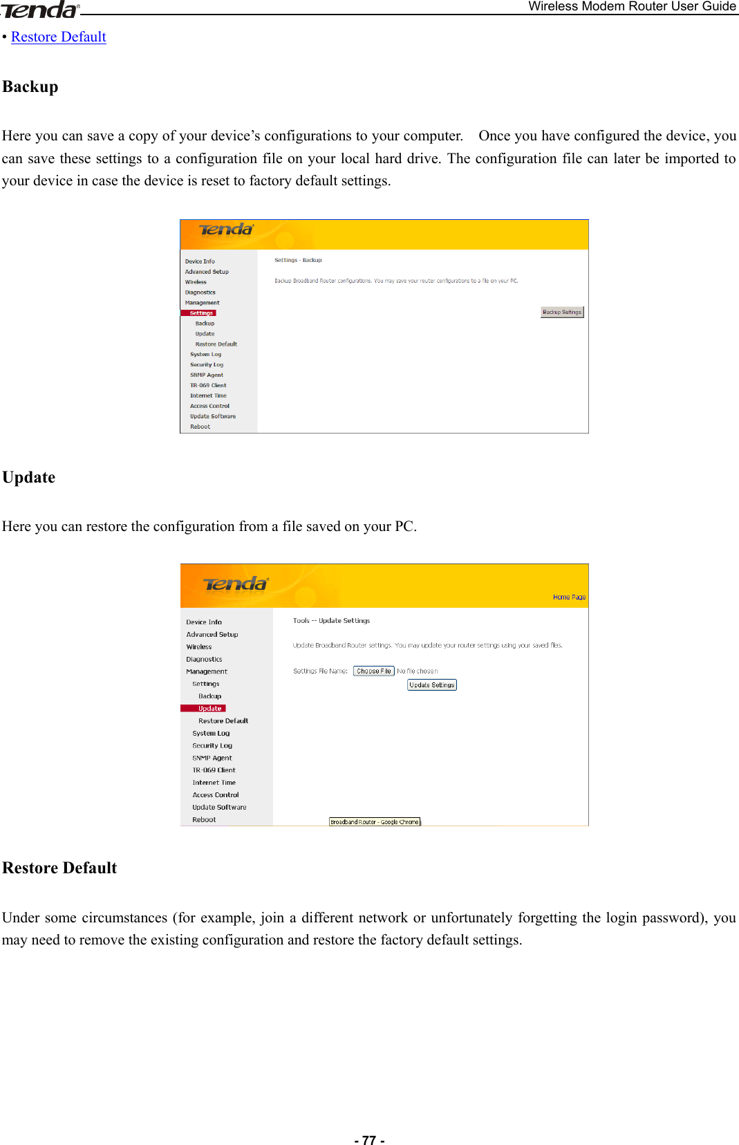
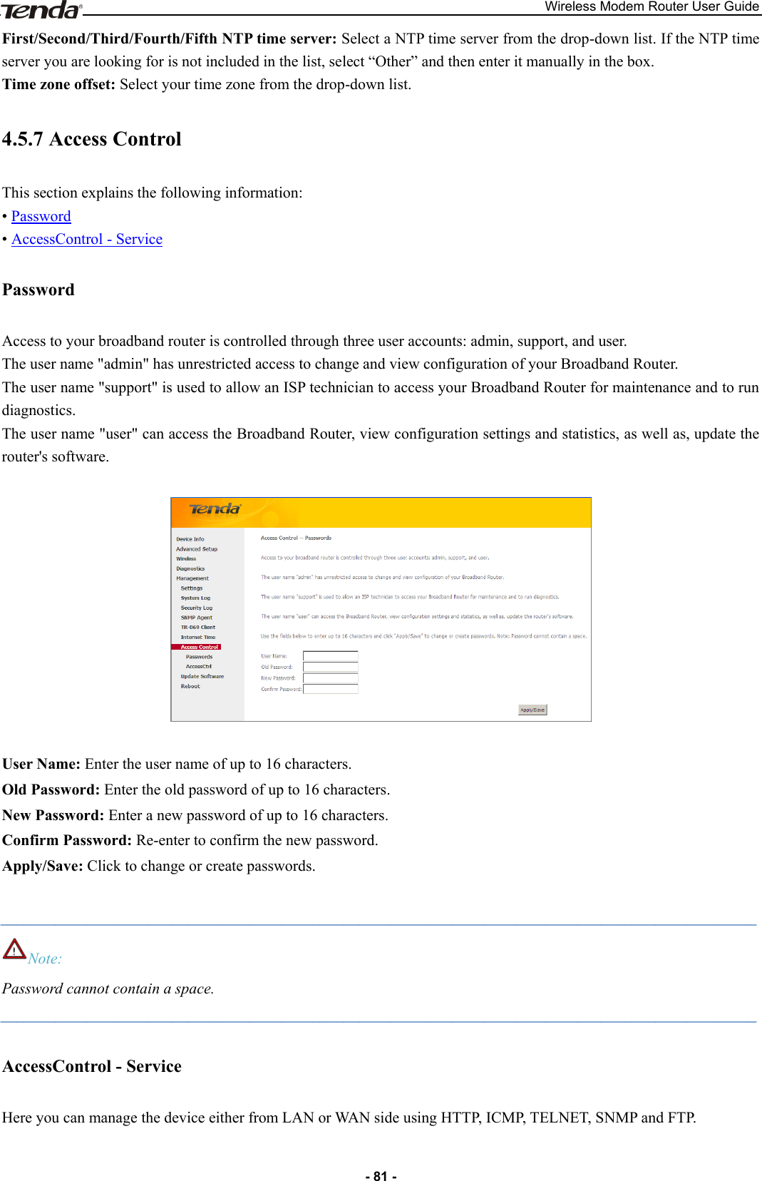
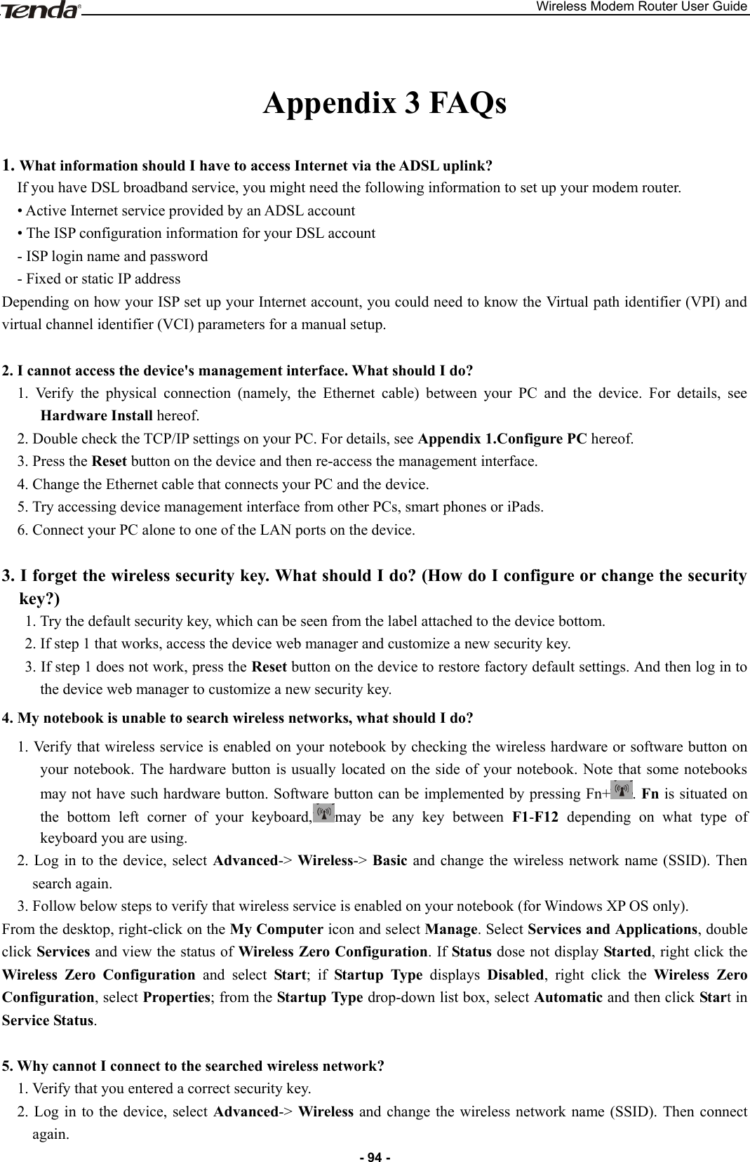
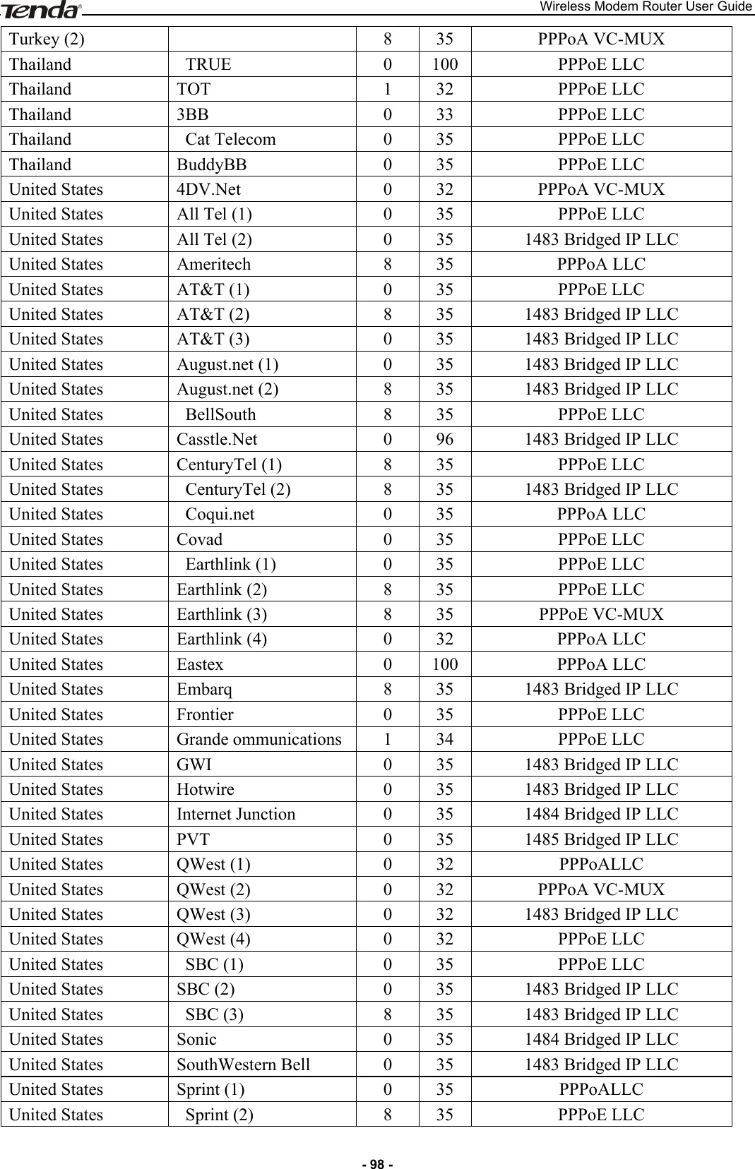
![Wireless Modem Router User Guide - 53 - This screen allows you to create a filter rule to identify incoming IP traffic by specifying a new filter name and at least one condition below. All of the specified conditions in this filter rule must be satisfied for the rule to take effect. Click Apply/Save to save and activate the filter. IP Version: Select either IPv4 or IPv6. Protocol: TCP/UDP, TCP, UDP and ICMP are available for your option. Source IP address [/prefix length]: Enter the Internal IP address [/prefix length] to be filtered. Source Port (port or port: port): Specify a port number or a range of ports used by PCs from external network to access your internal network. Destination IP address [/prefix length]: Specify the internal network IP address [/prefix length] to be accessed by the specified PCs from external network. Destination Port (port or port:port): Specify a port number or a range of ports used by PCs from external network to access your internal network. MAC Filtering A bridge WAN service is needed to configure this service. MAC Filtering is only effective on ATM PVCs configured in Bridge mode. FORWARDED means that all MAC layer frames will be FORWARDED except those matching with any of the specified rules in the following table. BLOCKED means that all MAC layer frames will be BLOCKED except those matching with any of the specified rules in the following table. Choose Add or Remove to configure MAC filtering rules. _________________________________________________________________________________________________ Warning! Changing from one policy to another of an interface will cause all defined rules for that interface to be REMOVED AUTOMATICALLY! You will need to create new rules for the new policy. _________________________________________________________________________________________________](https://usermanual.wiki/TENDA-TECHNOLOGY/D151.Users-Manual-Part-2/User-Guide-2092079-Page-3.png)
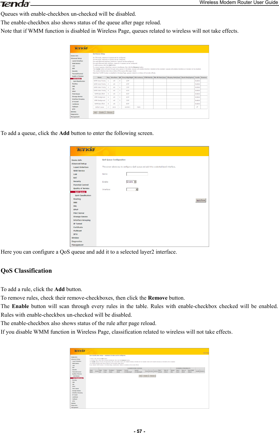
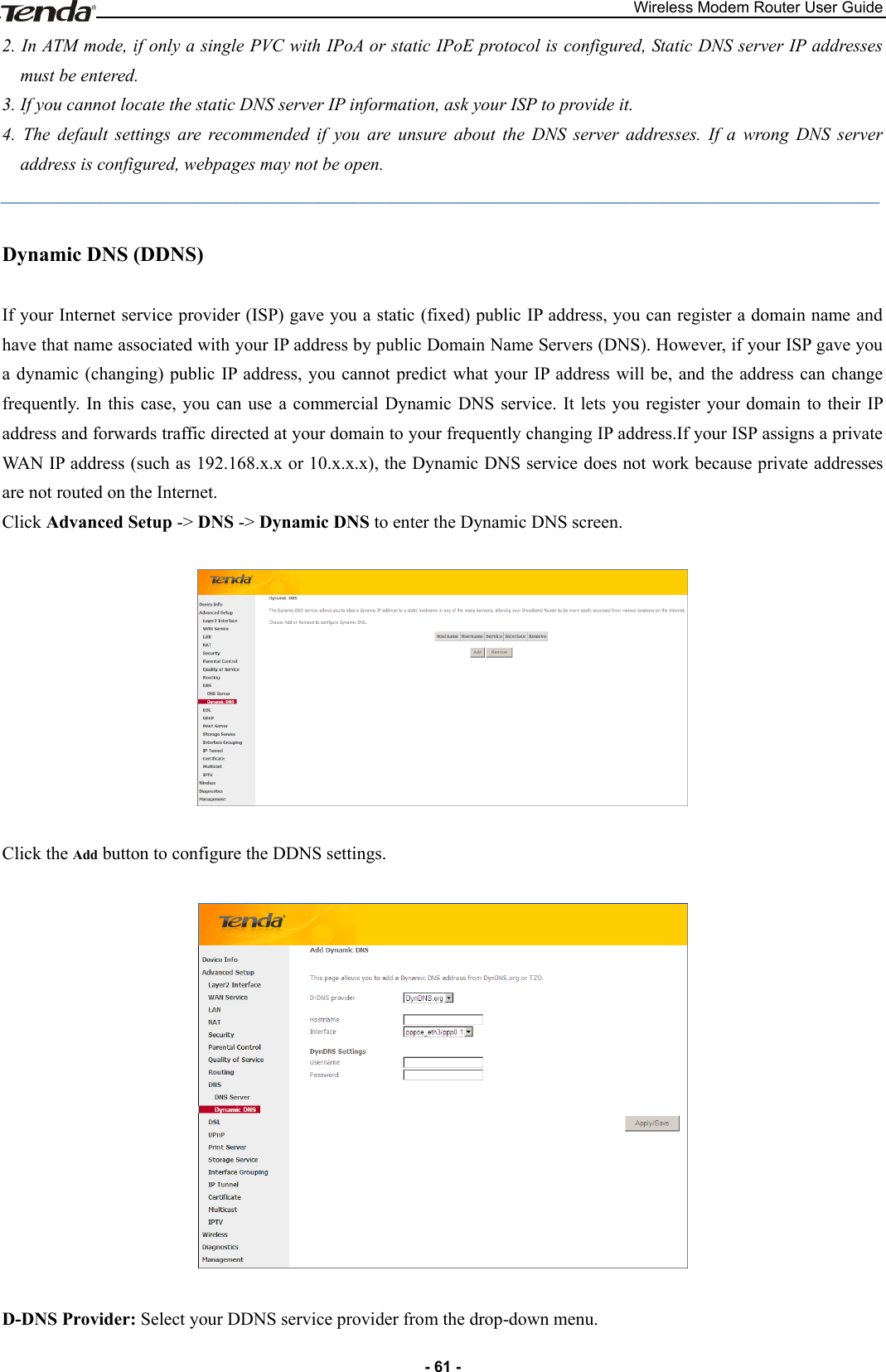
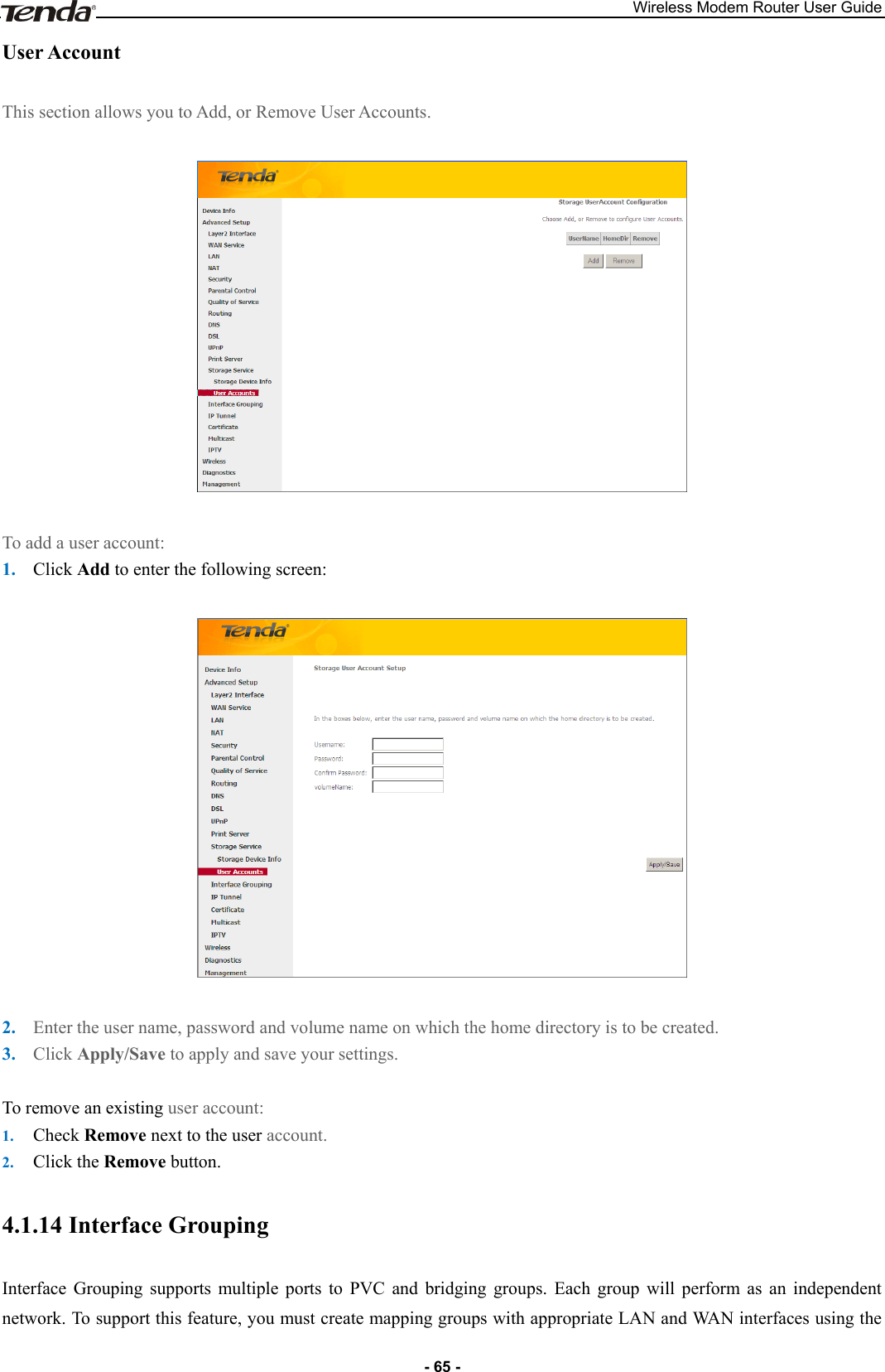
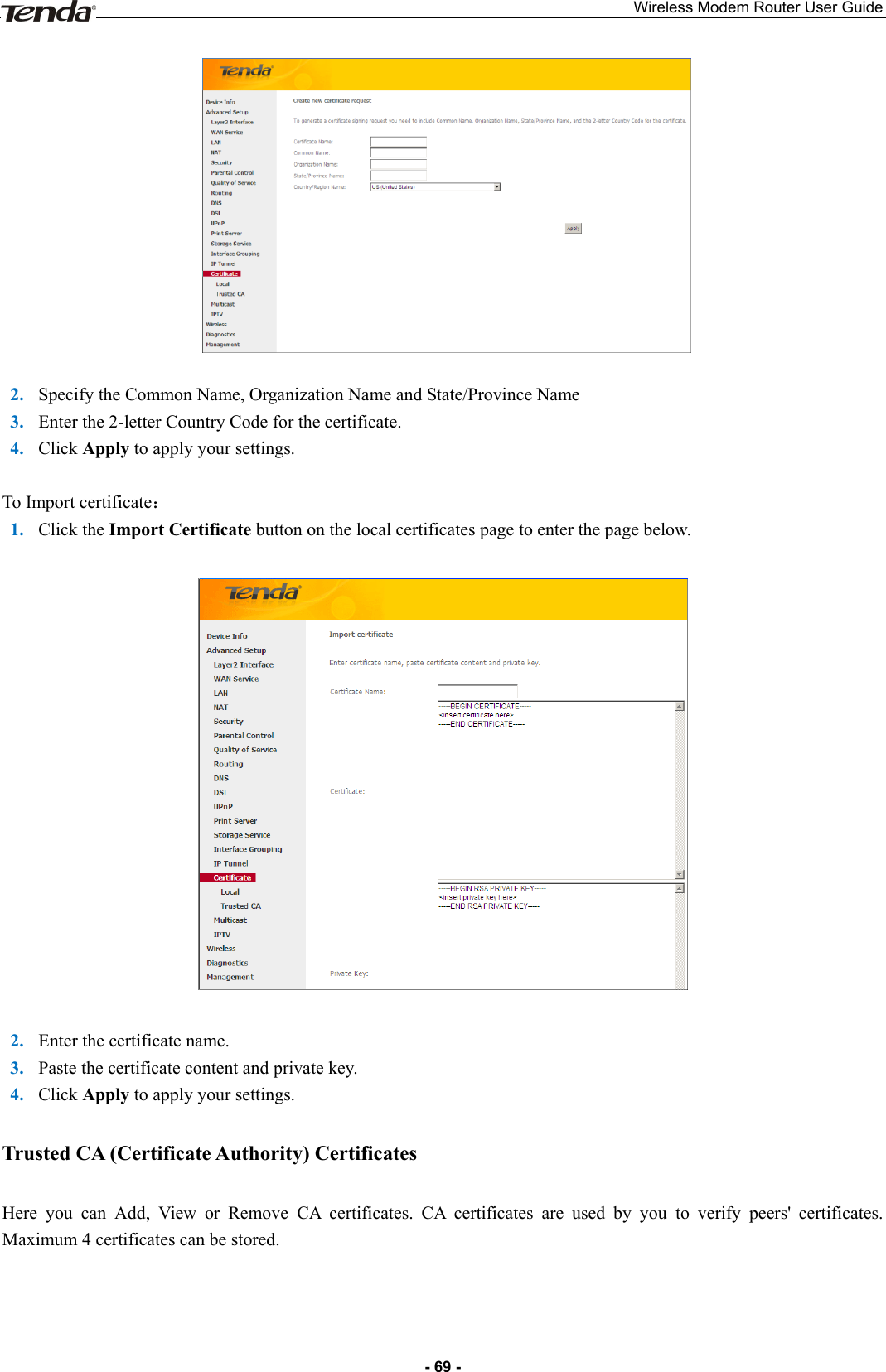

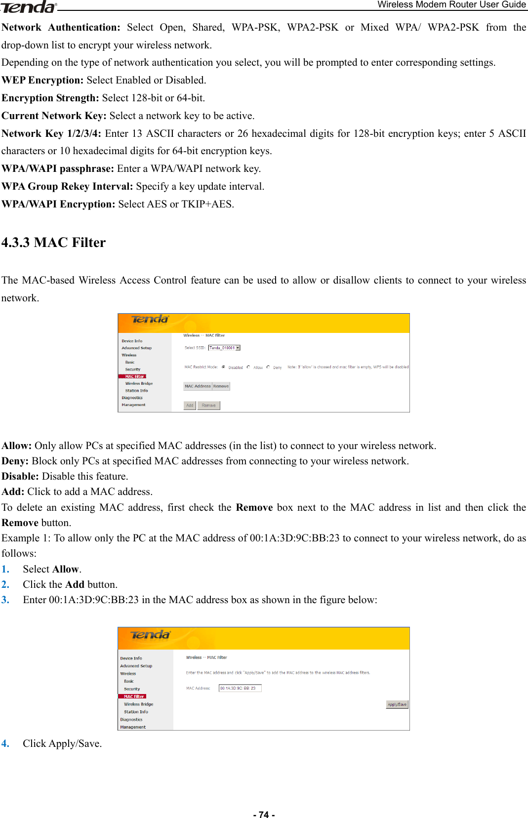
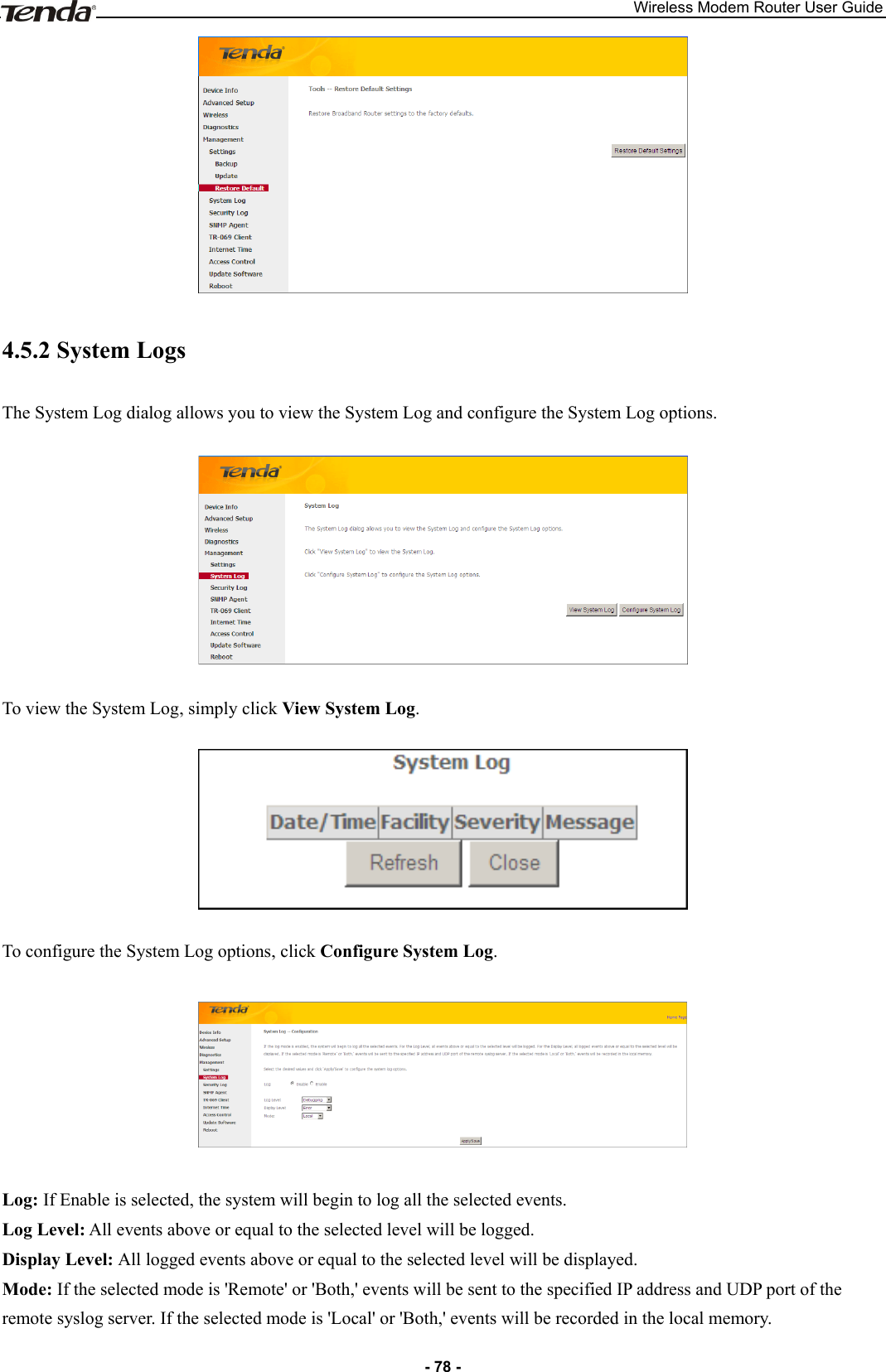
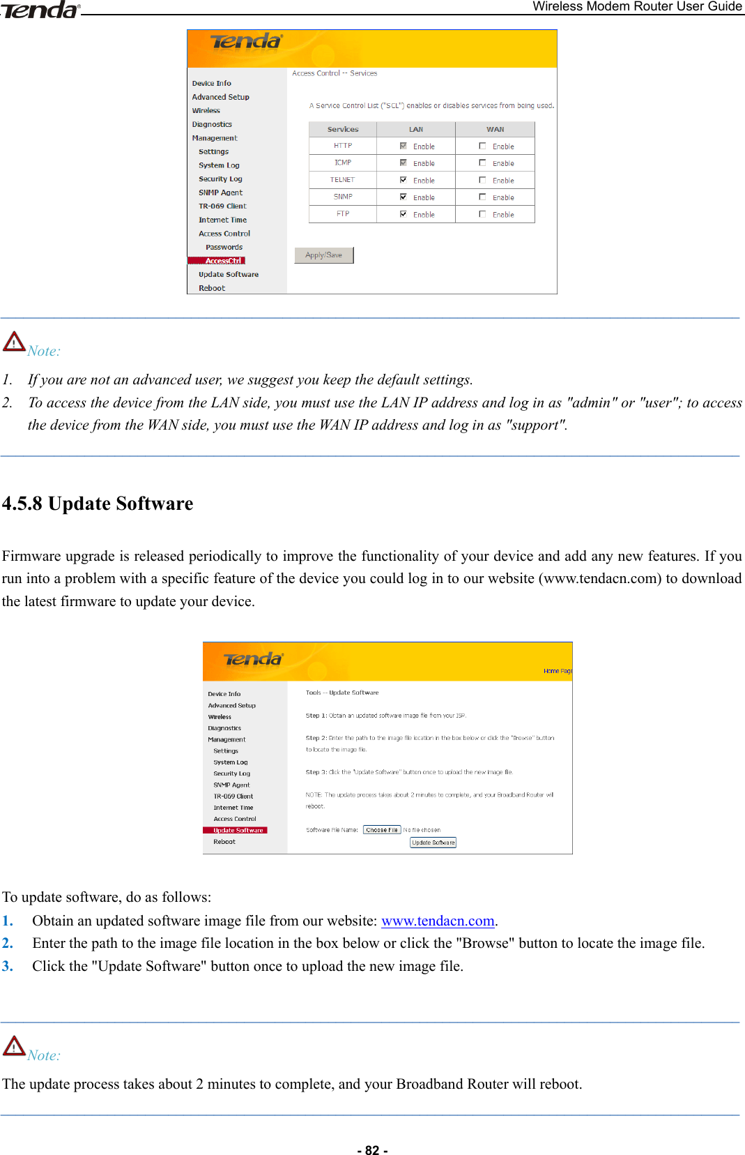

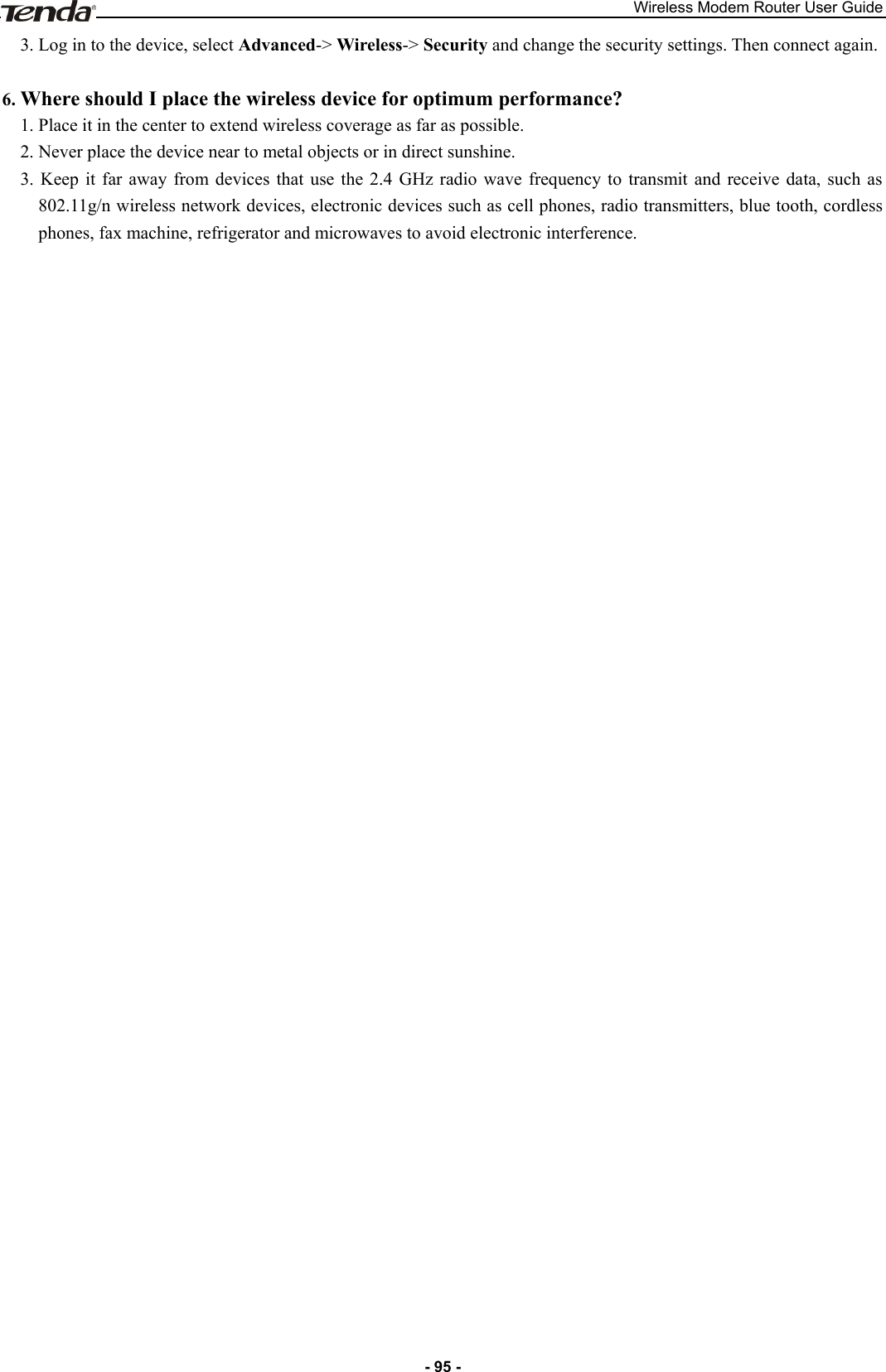
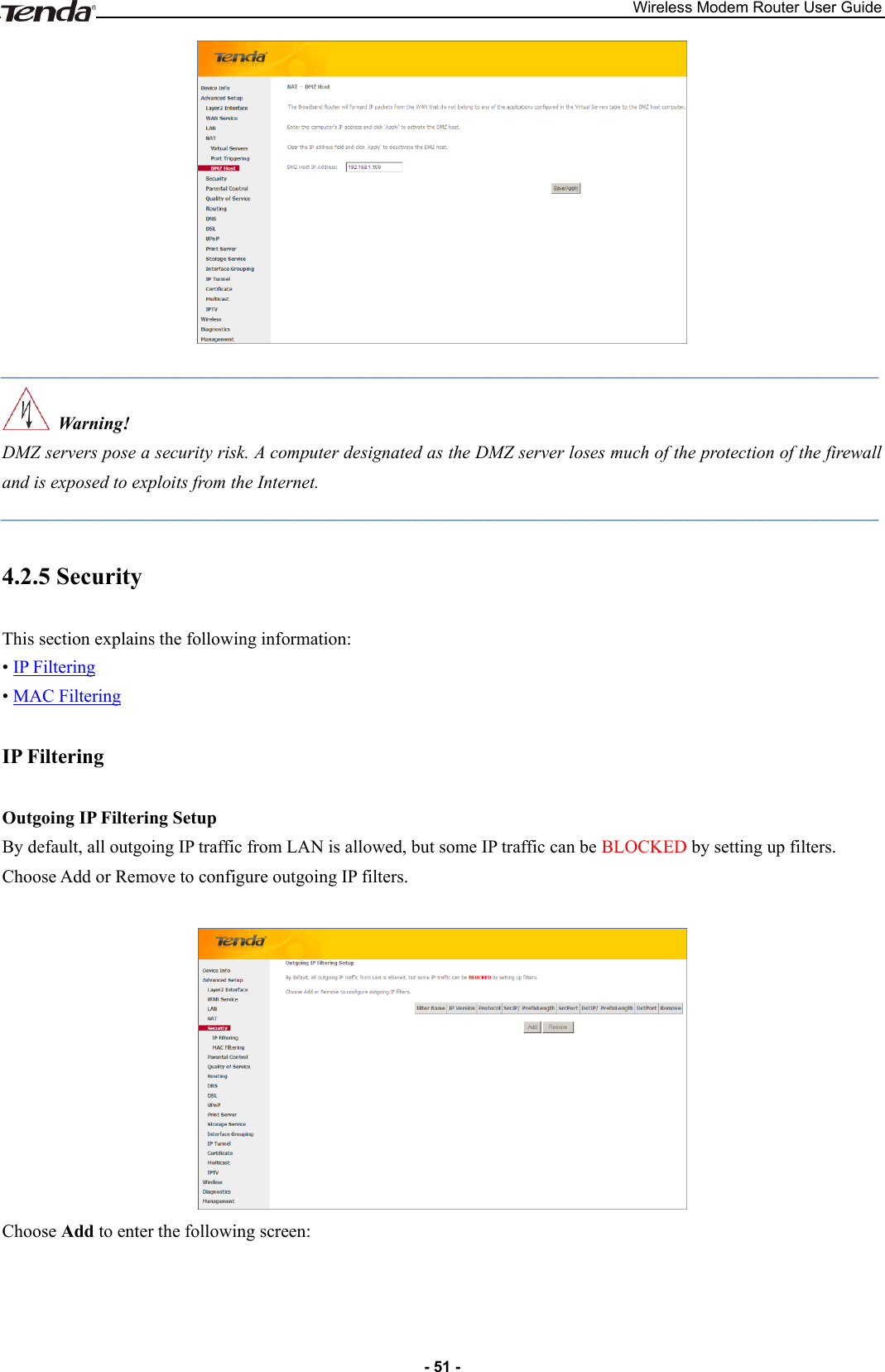
![Wireless Modem Router User Guide - 101 - Finland Saunalahti 0 100 1483 Bridged IP LLC Finland Elisa 0 100 1483 Bridged IP LLC Finland DNA 0 100 1483 Bridged IP LLC Finland Sonera 0 35 1483 Bridged IP LLC Iran [Shatel] Aria-Rasaneh-Tadbir 0 35 PPPOE LLC Iran Asia-Tech 0 35 PPPOE LLC Iran Pars-Online (Tehran) 0 35 PPPOE LLC Iran Pars-Online (Provinces) 0 59 PPPOE LLC Iran [Saba-Net] Neda-Gostar-Saba 0 35 PPPOE LLC Iran Pishgaman-Tose 0 35 PPPOE LLC Iran Fan-Ava 8 35 PPPOE LLC Iran Datak 0 35 PPPOE LLC Iran Laser (General) 0 35 PPPOE LLC Iran Laser (Privates) 0 32 PPPOE LLC Iran Asr-Enteghal-Dadeha 8 35 PPPOE LLC Iran Kara-Amin-Ertebat 0 33 PPPOE LLC Iran ITC 0 35 PPPOE LLC Iran Dadegostar Asre Novin 0 33 PPPOE LLC India Airtel 1 32 1483 Bridged IP LLC India BSNL 0 35 1483 Bridged IP LLC India MTNL 0 35 1483 Bridged IP LLC India RELIANCE COMMUNICATION 0 35 PPPOE LLC India TATA INDICOM 0 32 PPPOE LLC India CONNECT 1 32 PPPOE LLC morocco IAM 8 35 PPPOE Malaysia Streamyx 0 35 PPPOE LLC Indonesia Speedy Telkomnet 8 81 PPPoE LLC](https://usermanual.wiki/TENDA-TECHNOLOGY/D151.Users-Manual-Part-2/User-Guide-2092079-Page-51.png)