TENDA TECHNOLOGY S108 8-PORT 10/100MBPS FAST ETHERNET SWITCH User Manual

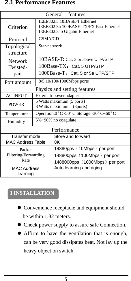
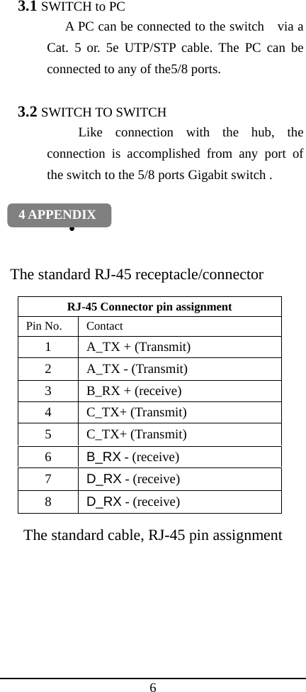
SHENZHEN TENDA TECHNOLOGY CO., LTD. 8-PORT 10/100MBPS FAST ETHERNET SWITCH Users Manual

Users Manual

       5/8 Ports   Gigabit Ethernet Switch       User’s Guide            VER:1.0
1  TABLE OF CONTENTS 1 INTRODUCTION   Unpacking ·················································· 2  Front Panel ················································· 2  Rear Panel  ················································ 2  Led Indicators············································· 2  Features······················································ 3 2 PERFORMANCE FEATURES  Performance Features ································· 5 3 INSTALLATION   SWITCH to PC··········································· 6  SWITCH TO SWITCH······························· 6 4  APPENDIX
2  1.1 Unpacking Open the box and carefully unpacks its contents. The box should contain the following items: •  One Gigabit Switch •  One external power adapter •  User’s Guide. If any item is found missing or damaged, please contact your dealer for replacement. 1.2 Front Panels For detail of the LED indicators in the front panel of the switch, refer to the LED Indicator section for detailed information about each of the 5/8 ports switch’s LED indicators. 1.3 Rear Panel There are 5/8 10/100/1000Mbps RJ45 port Jacks and one DC Power Jack in.   Attention: Please use power adapter original from the supplier, otherwise please consult with the supplier.    An improper adapter may cause permanent damage to the switch. 1.4 LED Indicators The LED indicators of the Switch include Power 、Link/ACT and 1000M. The LED indicators are used to facilitate monitoring and troubleshooting of the Switch. The following shows the LED indicators for the Switch along with explanation of each indicator. 1 INTRODUCTION
3 1.5 Features The 5/8-port Gigabit Ethernet Switch provides you with a high-performance, low-cost, easy-to-use, seamless and standard upgrade to boost your old network to 1000Mbps. Increase the speed of your network server and backbone connections make Gigabit a reality. Power users in the home, office, workgroup, or creative production environment can now move large, LED Indicator  Color Status  Description Green Light  This indicates the Switch is turned on POWER — ExtinguishIf this indicator is not light, check the AC power connector to ensure proper insertion of the     power cord and the power switch is turned on. Green Light  The port is connected to a Ethernet station LINK/ ACT Green Blinking  The port is transmitting or receiving data Green Light The port is  connected to a 1000Mbps  Ethernet stationI 1000M — ExtinguishThe port is connected to a 10/100Mbps  Fast   Ethernetstation
4 bandwidth-intensive files faster. The 5/8 ports switch combines large dynamic memory allocation with store-and forward switching to ensure that the buffer is effectively allocated for each port, while controlling the data flow between the transmit and receive nodes to guarantee against all possible packet loss. It    can detect 10M/100M/1000M and full duplex/half duplex mode, plug-and-play and no configuration is required.      1. Complies with IEEE802.3, IEEE802.3u,       IEEE802.3ab standards 2.  NWAY Auto-negotiation support, Auto-Sense the transmission speed, half/full duplex, avoiding  the complicate procedure of settings, plug and play. 3.  5/8 ports 10/100/1000M Auto-Sense RJ45 ports supporting Auto-MDI/MDIX 4.    Supports IEEE802.3x flow control for full-duplex model and backpressure for half-duplex transfer model 5.  Provide 10/16G backplance bandwidth, support non-blocking wire-speed transfer.                 6.    Adopt store and forward structure, MAC address auto learning, integration    2 PERFORMANCE FEATURES
5 2.1 Performance Features    z Convenience receptacle and equipment should   be within 1.82 meters. z Check power supply to assure safe Connection. z Affirm to have the ventilation that is enough, can be very good dissipates heat. Not lay up the heavy object on switch.  General  features Criterion IEEE802.3 10BASE-T Ethernet IEEE802.3u 100BASE-TX/FX Fast Ethernet IEEE802.3ab Gigabit Ethernet Protocol  CSMA/CD Topological structure Star-network Network Twisted- pair 10BASE-T: Cat. 3 or above UTP/STP 100Base-TX:Cat. 5 UTP/STP 1000Base-T:Cat. 5 or 5e UTP/STP Port amount 8/5 10/100/1000Mbps ports Physics and setting features AC INPUT  Externalr power adapter POWER  5 Watts maximum (5 ports) 8 Watts maximum    (8ports) Temperature  Operation:0°C~50°C Storage:-30°C~60°C Humidity  5%~90% no coagulate Performance Transfer mode  Store and forward MAC Address Table  8K 14880pps(10Mbps)per port 148800pps(100Mbps)per port Packet Filtering/Forwarding Rate  1488000pps(1000Mbps)per port MAC Address learning Auto learning and aging 3 INSTALLATION
6 3.1 SWITCH to PC A PC can be connected to the switch    via a Cat. 5 or. 5e UTP/STP cable. The PC can be connected to any of the5/8 ports.  3.2 SWITCH TO SWITCH Like connection with the hub, the connection is accomplished from any port of the switch to the 5/8 ports Gigabit switch .  •   The standard RJ-45 receptacle/connector The standard cable, RJ-45 pin assignment RJ-45 Connector pin assignment Pin No. Contact 1  A_TX + (Transmit) 2  A_TX - (Transmit) 3  B_RX + (receive) 4 C_TX+ (Transmit) 5 C_TX+ (Transmit) 6  B_RX - (receive) 7  D_RX - (receive) 8  D_RX - (receive) 4 APPENDIX
7 FCC WARNING  This device complies with Part 15 of the FCC Rules. Operation is subject to the following two conditions: (1) this device may not cause harmful interference, and (2) this device must accept any interference received, including interference that may cause undesired operation.  NOTE 1: This equipment has been tested and found to comply with the limits for a Class B digital device, pursuant to part 15 of the FCC Rules. These limits are designed to provide reasonable protection against harmful interference in a residential installation. This equipment generates, uses and can radiate radio frequency energy and, if not installed and used in accordance with the instructions, may cause harmful interference to radio communications. However, there is no guarantee that interference will not occur in a particular installation. If this equipment does cause harmful interference to radio or television reception, which can be determined by turning the equipment off and on, the user is encouraged to try to correct the interference by one or more of the following measures: - Reorient or relocate the receiving antenna. - Increase the separation between the equipment and receiver. -Connect the equipment into an outlet on a
8 circuit different from that to which the receiver is connected. -Consult the dealer or an experienced radio/TV technician for help.  NOTE 2: The manufacturer is not responsible for and radio or TV interference caused by unauthorized modifications to this equipment. Such modifications could void the user’s authority to operate the equipment.

Navigation menu