THALES DIS AlS Deutschland AGS2 GSM 850/900/1800/1900 GPRS Module User Manual hid
Gemalto M2M GmbH GSM 850/900/1800/1900 GPRS Module hid
UserManual.wiki
>
THALES DIS AlS Deutschland
>
AGS2 User Manual
08 installation manual
Navigation menu
Upload a User Manual
Namespaces
Wiki Guide
HTML
PDF
Info
Views
User Manual
Discussion / Help
Navigation
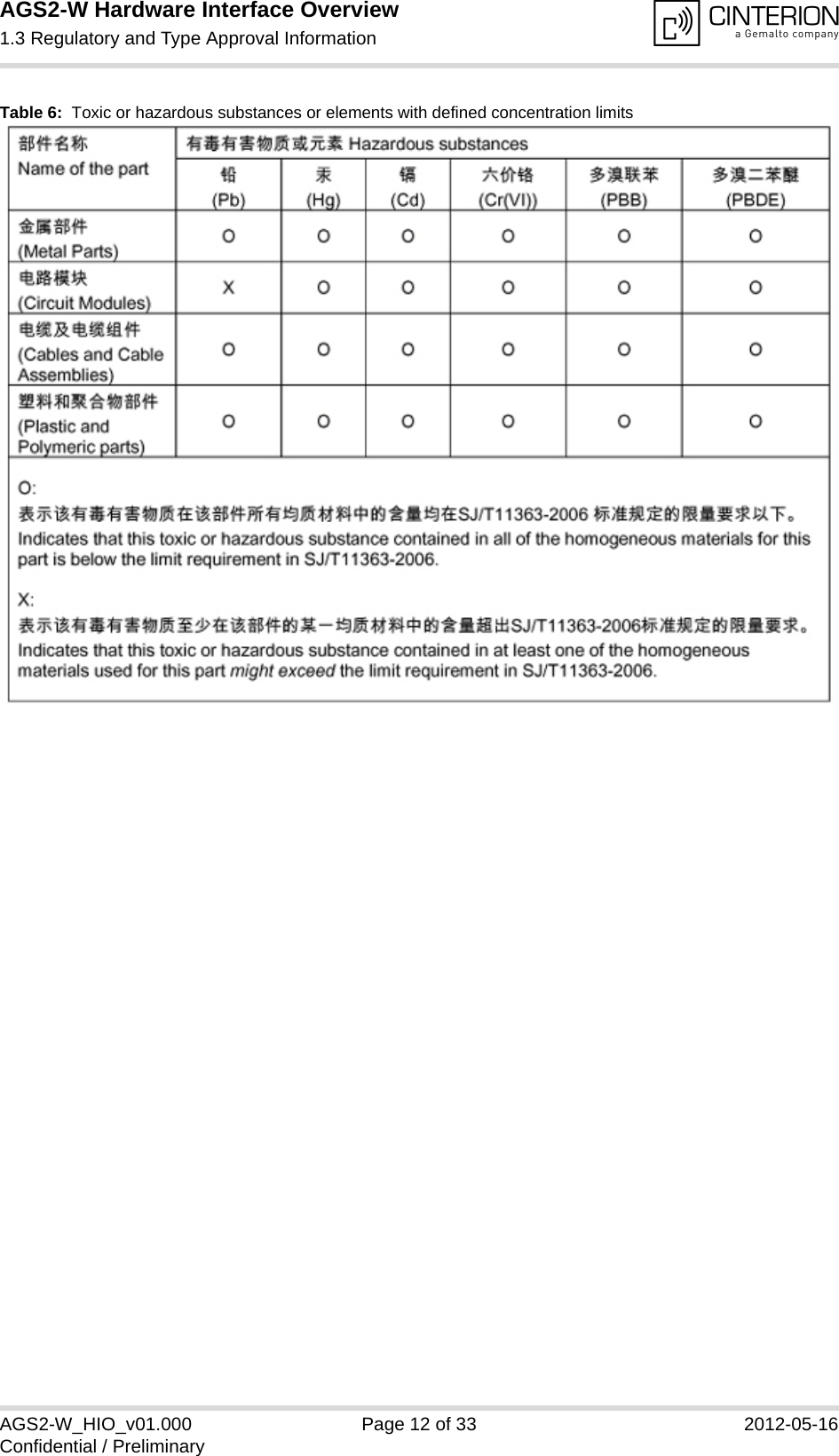
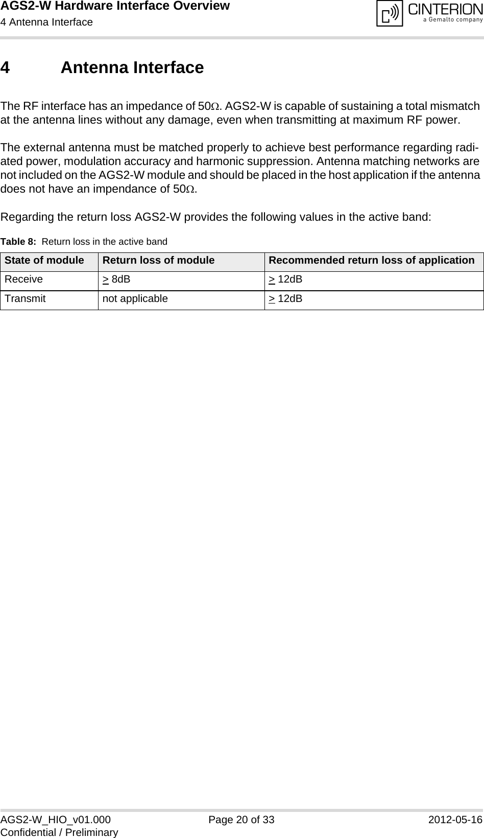
![AGS2-W Hardware Interface Overview1 Introduction14AGS2-W_HIO_v01.000 Page 6 of 33 2012-05-16Confidential / Preliminary1 IntroductionThis document1 describes the hardware of the Cinterion AGS2-W module that connects to the cellular device application and the air interface. It helps you quickly retrieve interface specifica-tions, electrical and mechanical details and information on the requirements to be considered for integrating further components.1.1 Related Documents[1] AGS2-W AT Command Set[2] AGS2-W Release Note[3] AGS2-W MPE calculation - Test report (Maximum Permissible Exposure)1.2 Terms and Abbreviations1. The document is effective only if listed in the appropriate Release Notes as part of the technicaldocumentation delivered with your Cinterion product.Abbreviation DescriptionADC Analog-to-digital converterAGC Automatic Gain ControlANSI American National Standards InstituteARFCN Absolute Radio Frequency Channel NumberARP Antenna Reference PointASC0/ASC1 Asynchronous Controller. Abbreviations used for first and second serial interface of AGS2-WB Thermistor ConstantBER Bit Error RateBTS Base Transceiver StationCB or CBM Cell Broadcast MessageCE Conformité Européene (European Conformity)CHAP Challenge Handshake Authentication ProtocolCPU Central Processing UnitCS Coding SchemeCSD Circuit Switched DataCTS Clear to SendDAC Digital-to-Analog ConverterDAI Digital Audio InterfacedBm0 Digital level, 3.14dBm0 corresponds to full scale, see ITU G.711, A-lawDCE Data Communication Equipment (typically modems, e.g. Cinterion GSM module)](https://usermanual.wiki/THALES-DIS-AlS-Deutschland/AGS2/User-Guide-1711275-Page-6.png)
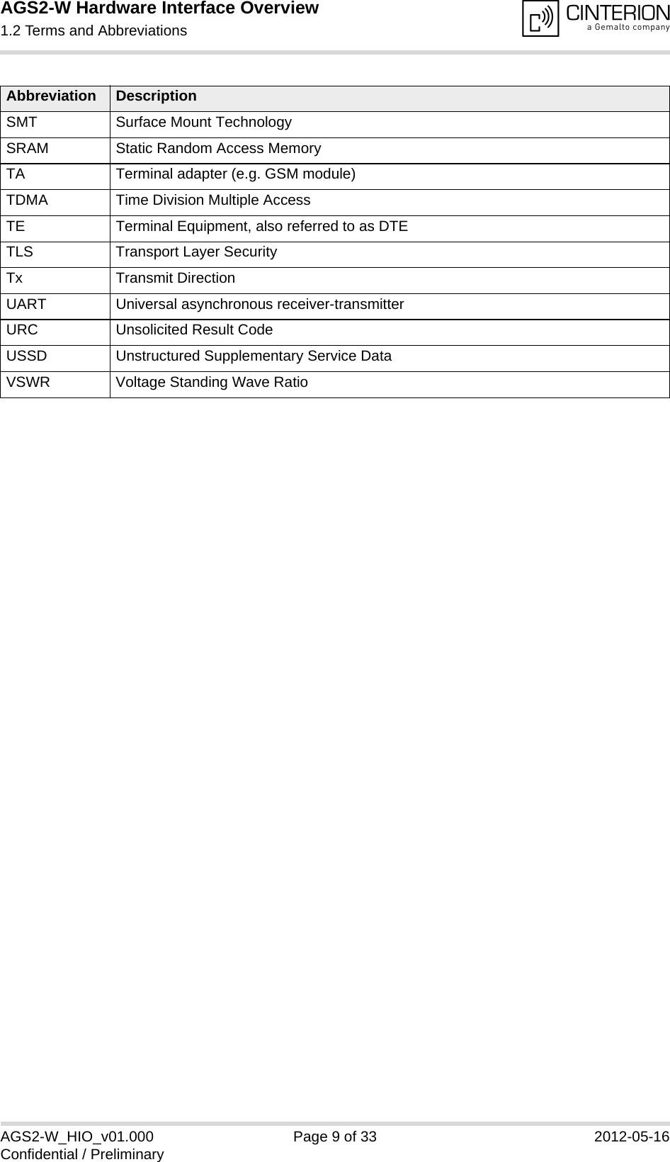
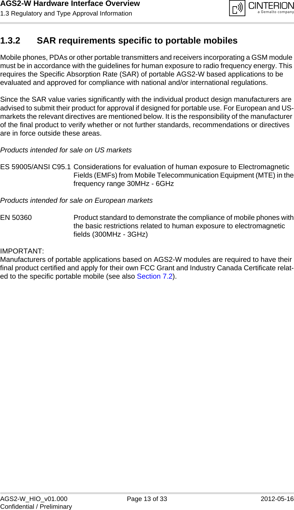
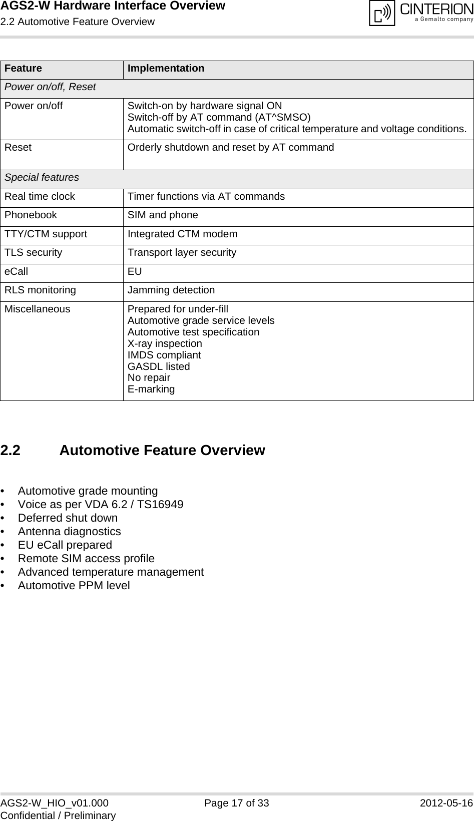
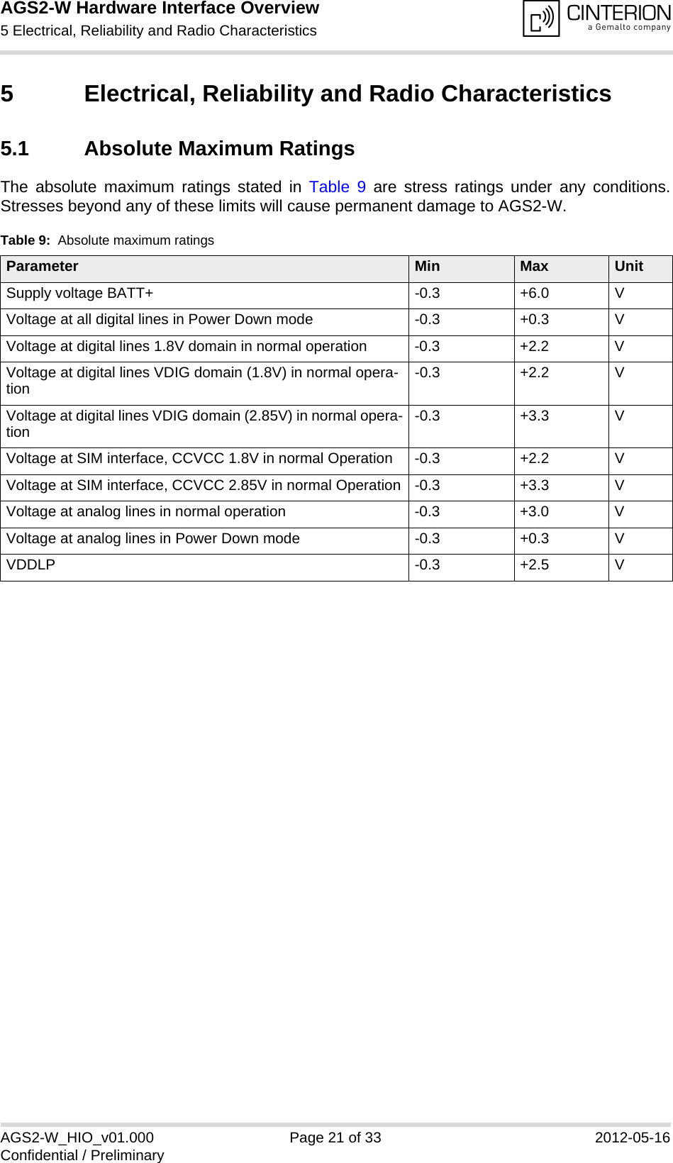
![AGS2-W Hardware Interface Overview5.2 Operating Temperatures28AGS2-W_HIO_v01.000 Page 22 of 33 2012-05-16Confidential / Preliminary5.2 Operating TemperaturesPlease note that the module’s lifetime, i.e., the MTTF (mean time to failure) may be reduced, ifoperated outside the extended temperature range. A special URC reports whether the moduleenters or leaves the extended temperature range (see [1]; AT^SCTM).Note that within the specified operating temperature ranges the board temperature may varyto a great extent depending on operating mode, used frequency band, radio output power andcurrent supply voltage. When data are transmitted over GPRS the module automatically reverts to a lower MultislotClass if the temperature rises to the limit specified for normal operation and, vice versa, returnsto the higher Multislot Class if the temperature is back to normal. Table 10: Board temperatureParameter Min Typ Max UnitNormal operation -30 +25 +85 °CExtended operation11. Extended operation allows normal mode speech calls or data transmission for limited time until automatic thermal shutdown takes effect. Within the extended temperature range (outside the normal operating temperature range) the specified electrical characteristics may be in- or decreased.-40 to -30 +85 to +90 °CAutomatic shutdown2Temperature measured on AGS2-Wboard2. Due to temperature measurement uncertainty, a tolerance of ±3°C on the thresholds may occur.<-40 --- >+90 °C](https://usermanual.wiki/THALES-DIS-AlS-Deutschland/AGS2/User-Guide-1711275-Page-22.png)
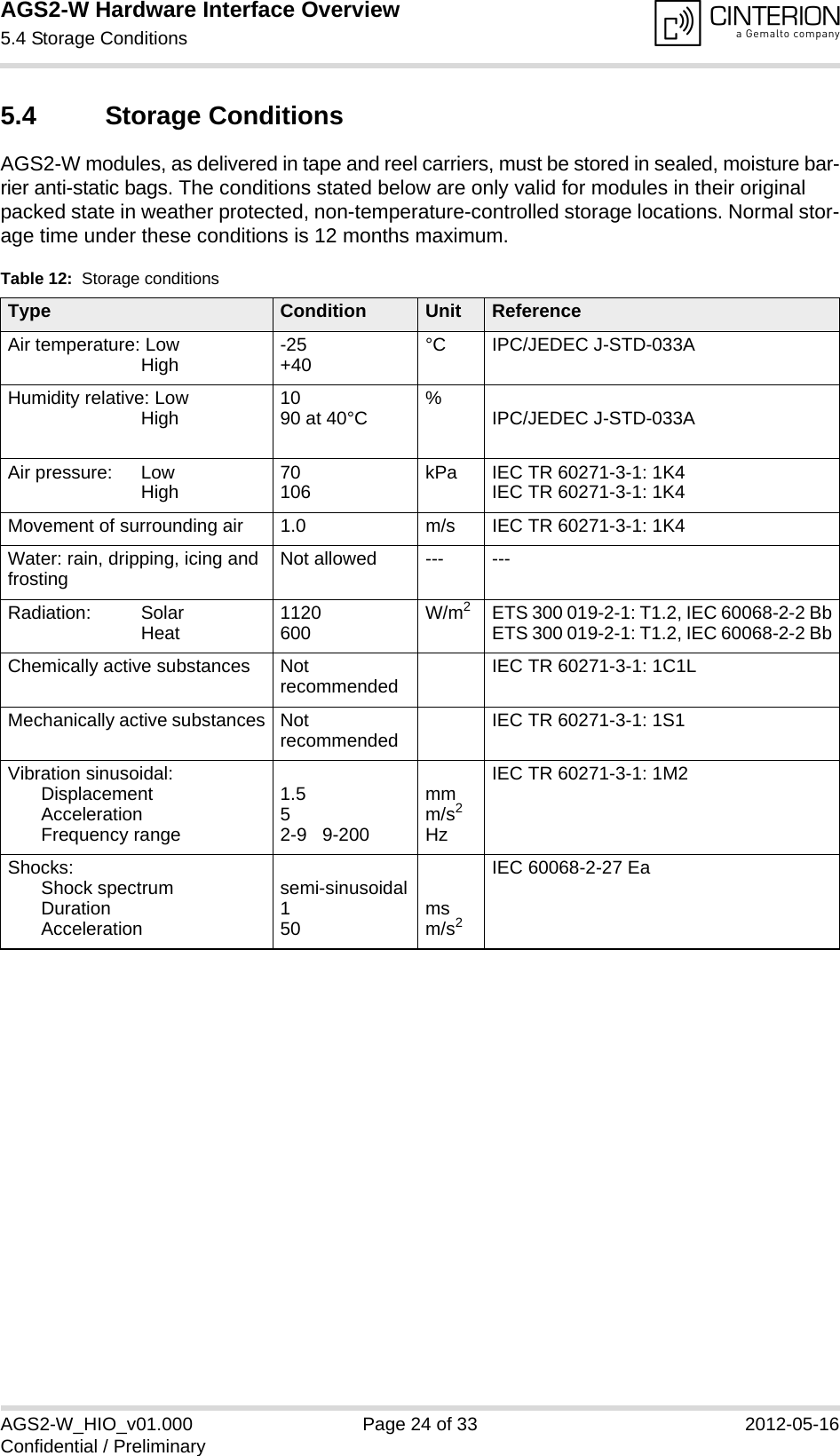
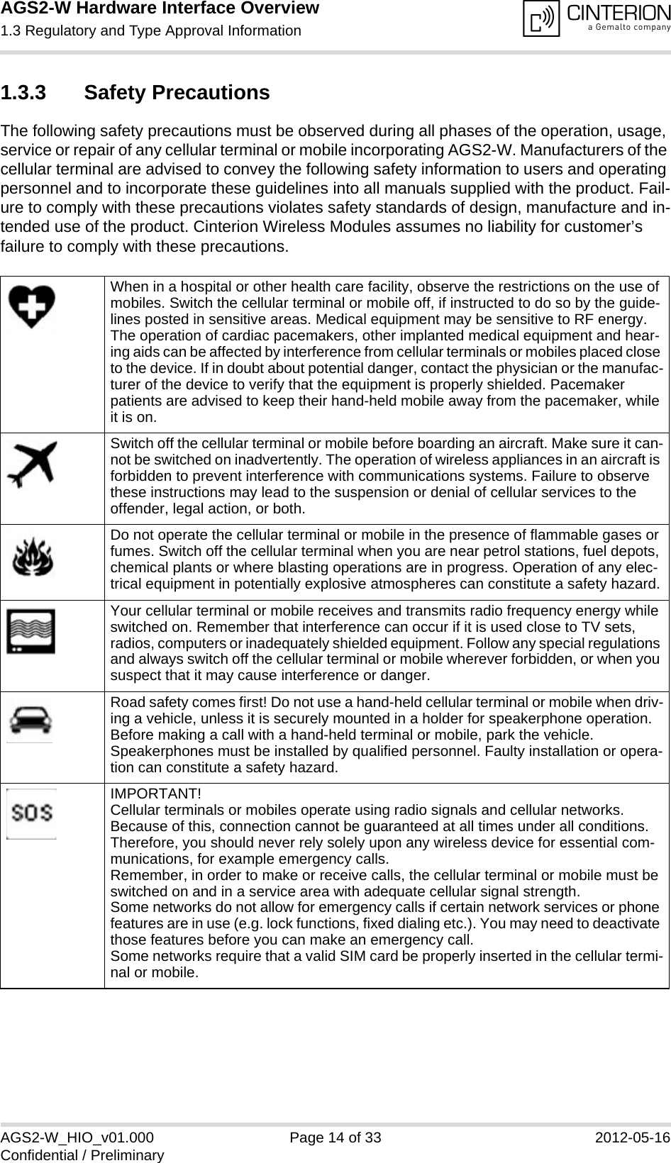
![AGS2-W Hardware Interface Overview7.2 Compliance with FCC and IC Rules and Regulations31AGS2-W_HIO_v01.000 Page 31 of 33 2012-05-16Confidential / Preliminary7.2 Compliance with FCC and IC Rules and RegulationsThe Equipment Authorization Certification for the Cinterion Wireless Modules reference appli-cation described in Section 7.1 will be registered under the following identifiers:FCC Identifier: QIPAGS2Industry Canada Certification Number: 7830A-AGS2Granted to Cinterion Wireless Modules GmbH Manufacturers of mobile or fixed devices incorporating AGS2-W modules are authorized to use the FCC Grants and Industry Canada Certificates of the AGS2-W modules for their own final products according to the conditions referenced in these documents. In this case, an FCC/ IC label of the module shall be visible from the outside, or the host device shall bear a second label stating "Contains FCC ID QIPAGS2", and accordingly “Contains IC 7830A-AGS2“.The integration is limited to fixed or mobile categorised host devices, where a separation dis-tance between the antenna and any person of min. 20cm can be assured during normal oper-ating conditions. For mobile and fixed operation configurations the antenna gain, including cable loss, must not exceed the limits 7.24 dBi (850 MHz) and 3.30 dBi (1900 MHz). See [3].IMPORTANT: Manufacturers of portable applications incorporating AGS2-W modules are required to have their final product certified and apply for their own FCC Grant and Industry Canada Certificate related to the specific portable mobile. This is mandatory to meet the SAR requirements for por-table mobiles (see Section 1.3.2 for detail).Changes or modifications not expressly approved by the party responsible for compliance could void the user's authority to operate the equipment.Note: This equipment has been tested and found to comply with the limits for a Class B digital device, pursuant to part 15 of the FCC Rules. These limits are designed to provide reasonable protec-tion against harmful interference in a residential installation. This equipment generates, uses and can radiate radio frequency energy and, if not installed and used in accordance with the instructions, may cause harmful interference to radio communications. However, there is no guarantee that interference will not occur in a particular installation. If this equipment does cause harmful interference to radio or television reception, which can be determined by turning the equipment off and on, the user is encouraged to try to correct the interference by one or more of the following measures:• Reorient or relocate the receiving antenna.• Increase the separation between the equipment and receiver.• Connect the equipment into an outlet on a circuit different from that to which the receiver isconnected.• Consult the dealer or an experienced radio/TV technician for help.The manufacturer is responsible for ensuring that after the module is installed and operational the host continues to be compliant with the Part 15B unintentional radiator requirements.](https://usermanual.wiki/THALES-DIS-AlS-Deutschland/AGS2/User-Guide-1711275-Page-31.png)