THALES DIS AlS Deutschland EHS6-A GSM/WCDMA Module User Manual EHS6 A Rev 2x
Gemalto M2M GmbH GSM/WCDMA Module EHS6 A Rev 2x
UserManual.wiki
>
THALES DIS AlS Deutschland
>
EHS6-A User Manual
>
EHS6-A_User Manual_Rev 2
Contents
1.
EHS6-A_User Manual_Rev 2
2.
ehs6-a_hio
EHS6-A_User Manual_Rev 2
Navigation menu
Upload a User Manual
Namespaces
Wiki Guide
HTML
PDF
Info
Views
User Manual
Discussion / Help
Navigation
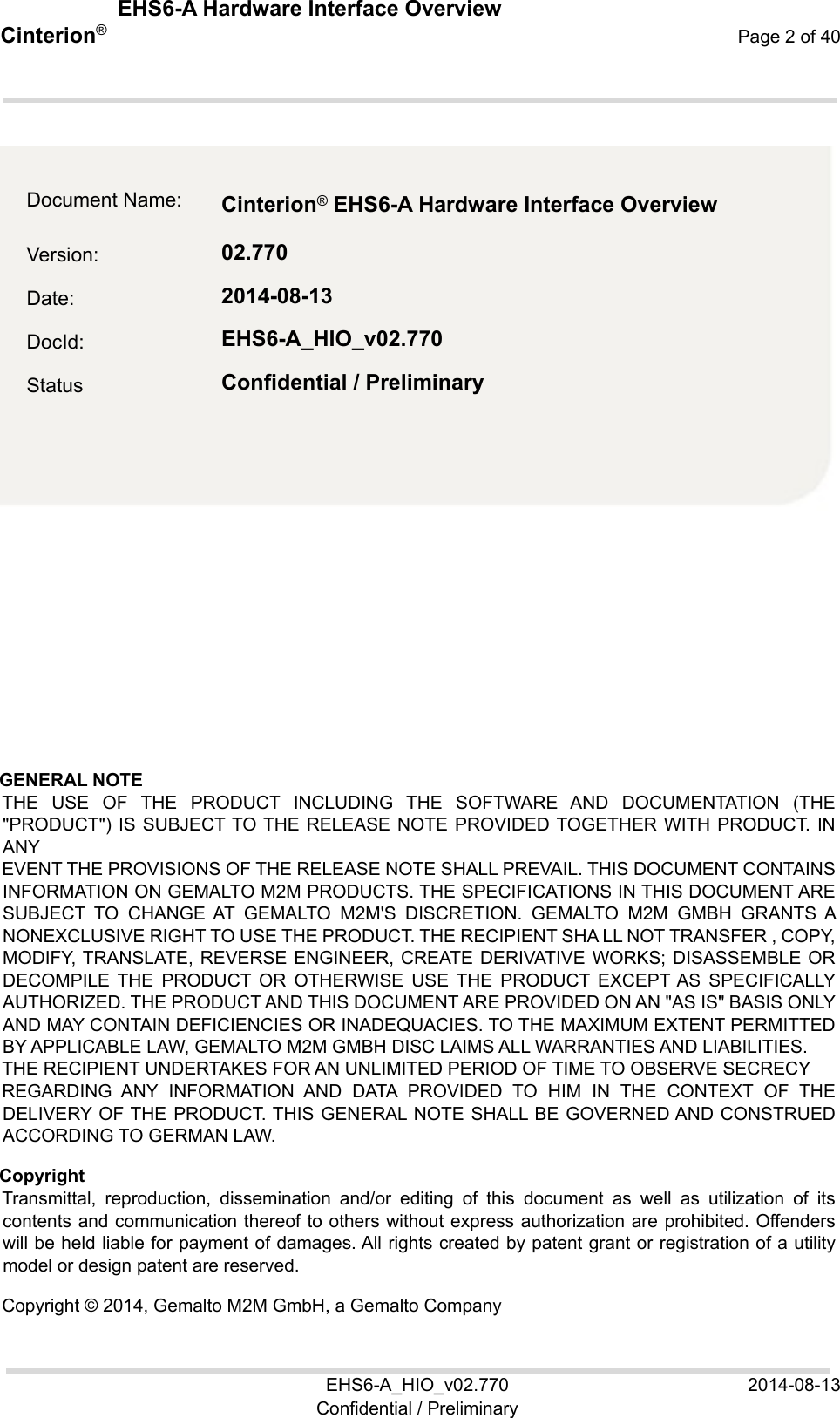
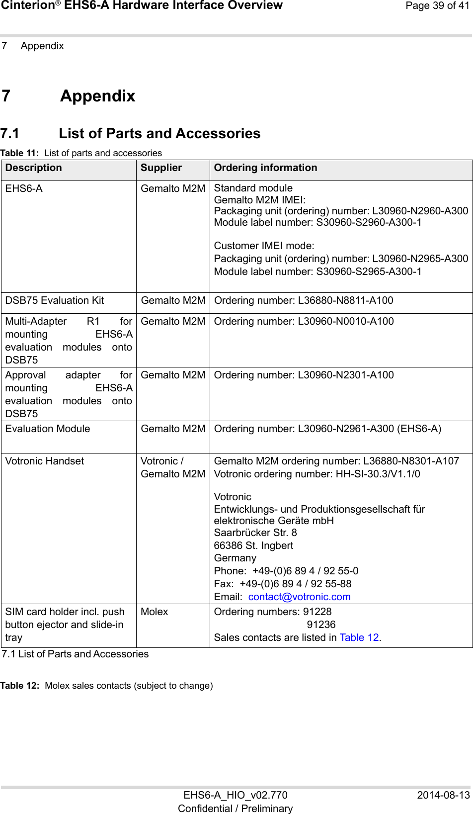
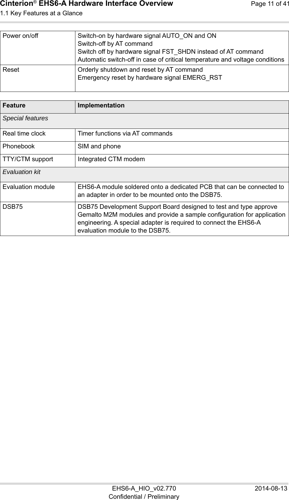
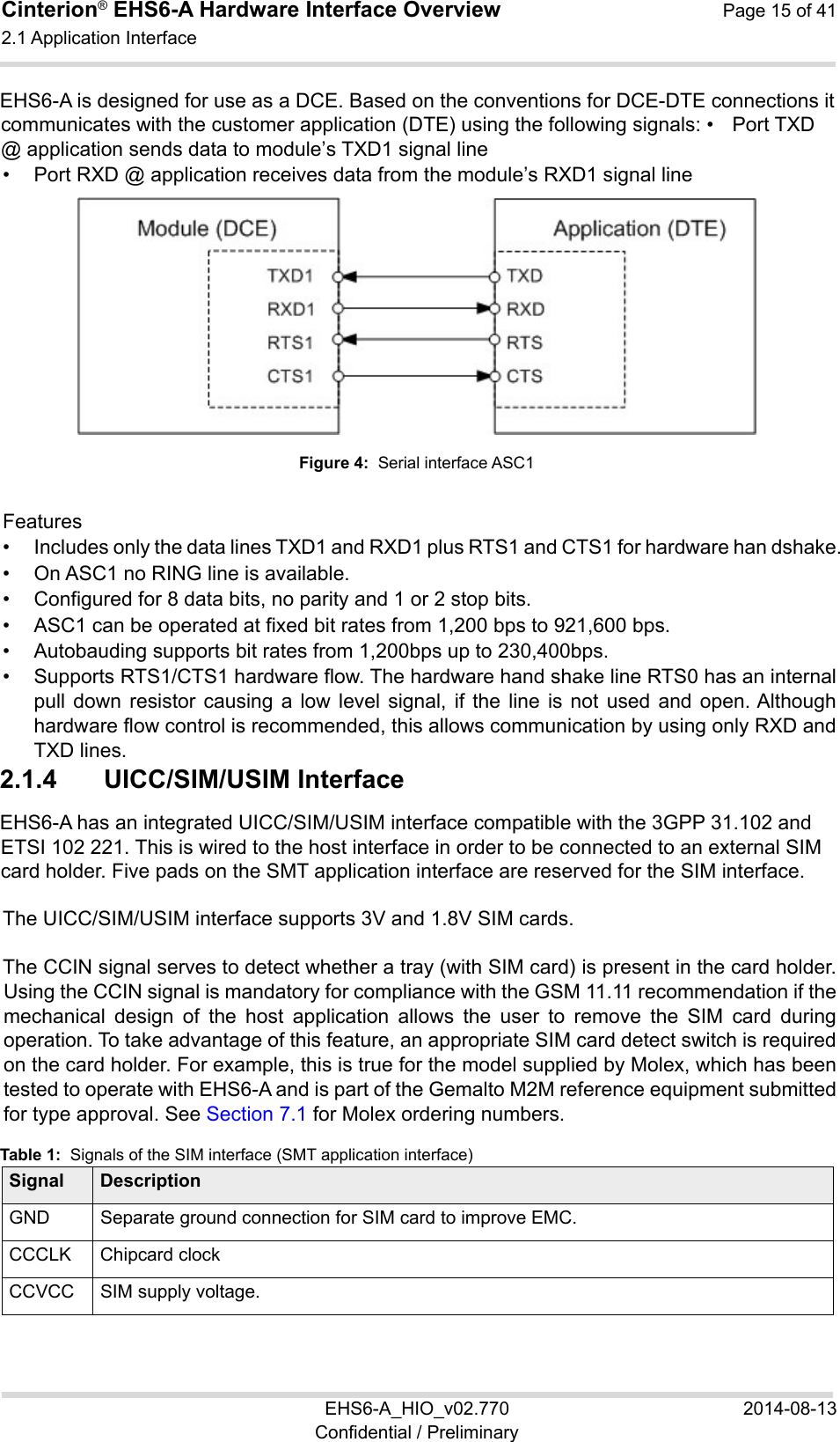
![Cinterion® EHS6-A Hardware Interface Overview Page 10 of 41 1.1 Key Features at a Glance 10 EHS6-A_HIO_v02.770 2014-08-13 Confidential / Preliminary Feature ImplementationMicrosoft™ compatibility RIL for Pocket PC and Smartphone SIM Application Toolkit SAT Release 99 Firmware update Generic update from host application over ASC0 or USB modem. Interfaces Module interface Surface mount device with solderable connection pads (SMT application interface). Land grid array (LGA) technology ensures high solder joint reliability and provides the possibility to use an optional module mounting socket. For more information on how to integrate SMT modules see also [3]. This application note comprises chapters on module mounting and application layout issues as well as on additional SMT application development equipment. USB USB 2.0 High Speed (480Mbit/s) device interface, Full Speed (12Mbit/s) compliant 2 serial interfaces ASC0 (shared with GPIO lines):• 8-wire modem interface with status and control lines, unbalanced, asynchronous • Adjustable baud rates: 1,200bps to 921,600bps • Autobauding: 1,200bps to 230,400bps • Supports RTS0/CTS0 hardware flow control. • Multiplex ability according to GSM 07.10 Multiplexer Protocol. ASC1 (shared with GPIO lines): • 4-wire, unbalanced asynchronous interface • Adjustable baud rates: 1,200bps to 921,60bps • Autobauding: 1,200bps to 230,400bps • Supports RTS1/CTS1 hardware flow control Audio 1 analog interface (with microphone feeding)1 digital interface (PCM), shared with GPIO lines UICC interface Supported SIM/USIM cards: 3V, 1.8V GPIO interface 14 GPIO lines shared with ASC0 lines, LED signalling, PWM functionality, fast shutdown and pulse counter 4 GPIO lines shared with PCM interface4 GPIO lines shared with ASC1, SPI and HSIC interfaces I2C interface Supports I2C serial interfaceHSIC interface High-Speed Inter-Chip (HSIC) interface for USB chip-to-chip interconnect including Link Power Management (LPM) lines shared with GPIO lines SPI interface Serial peripheral interface, shared with GPIO linesAntenna interface pads 50 Power on/off, Reset](https://usermanual.wiki/THALES-DIS-AlS-Deutschland/EHS6-A.EHS6-A-User-Manual-Rev-2/User-Guide-2388095-Page-10.png)
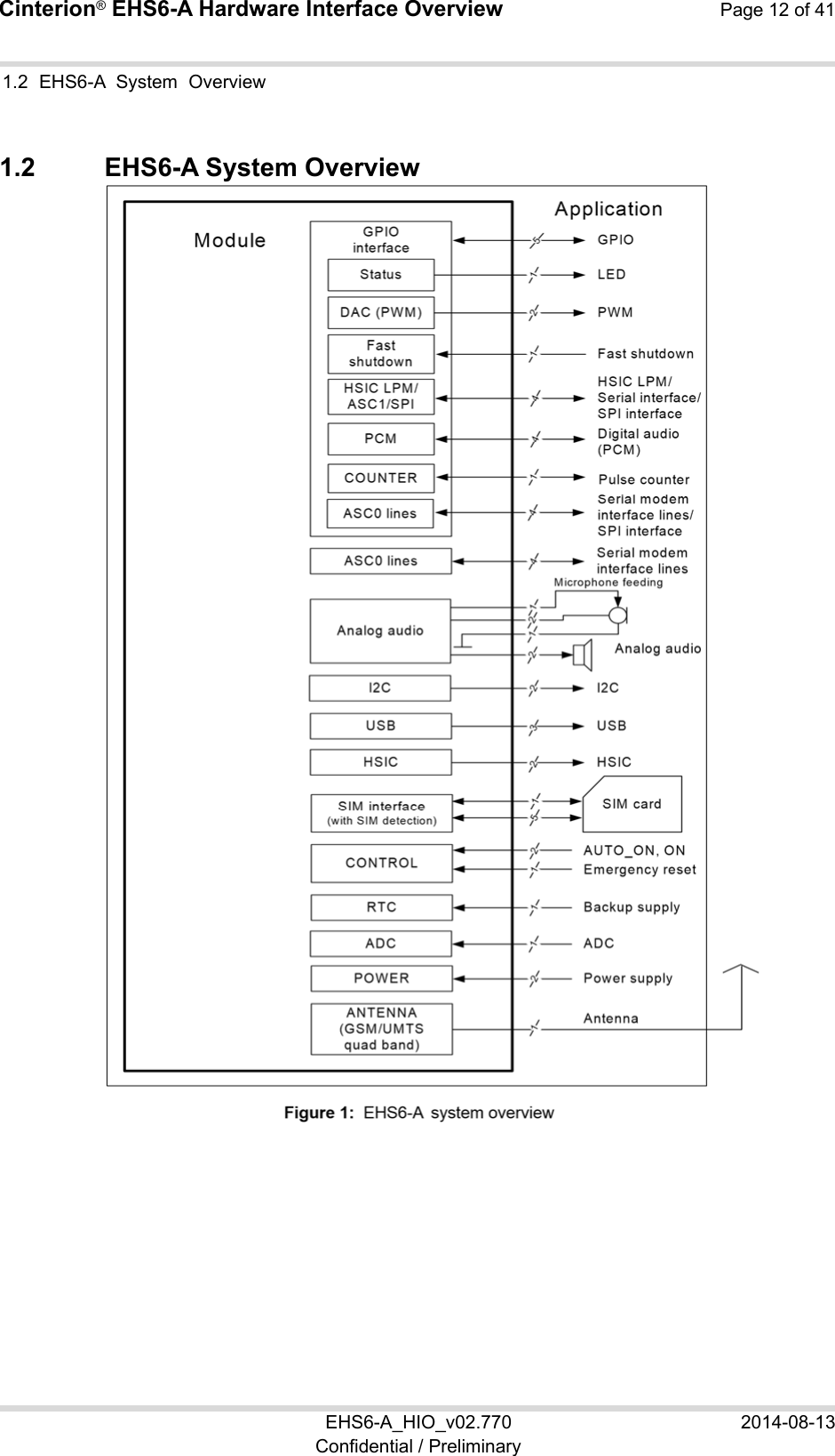
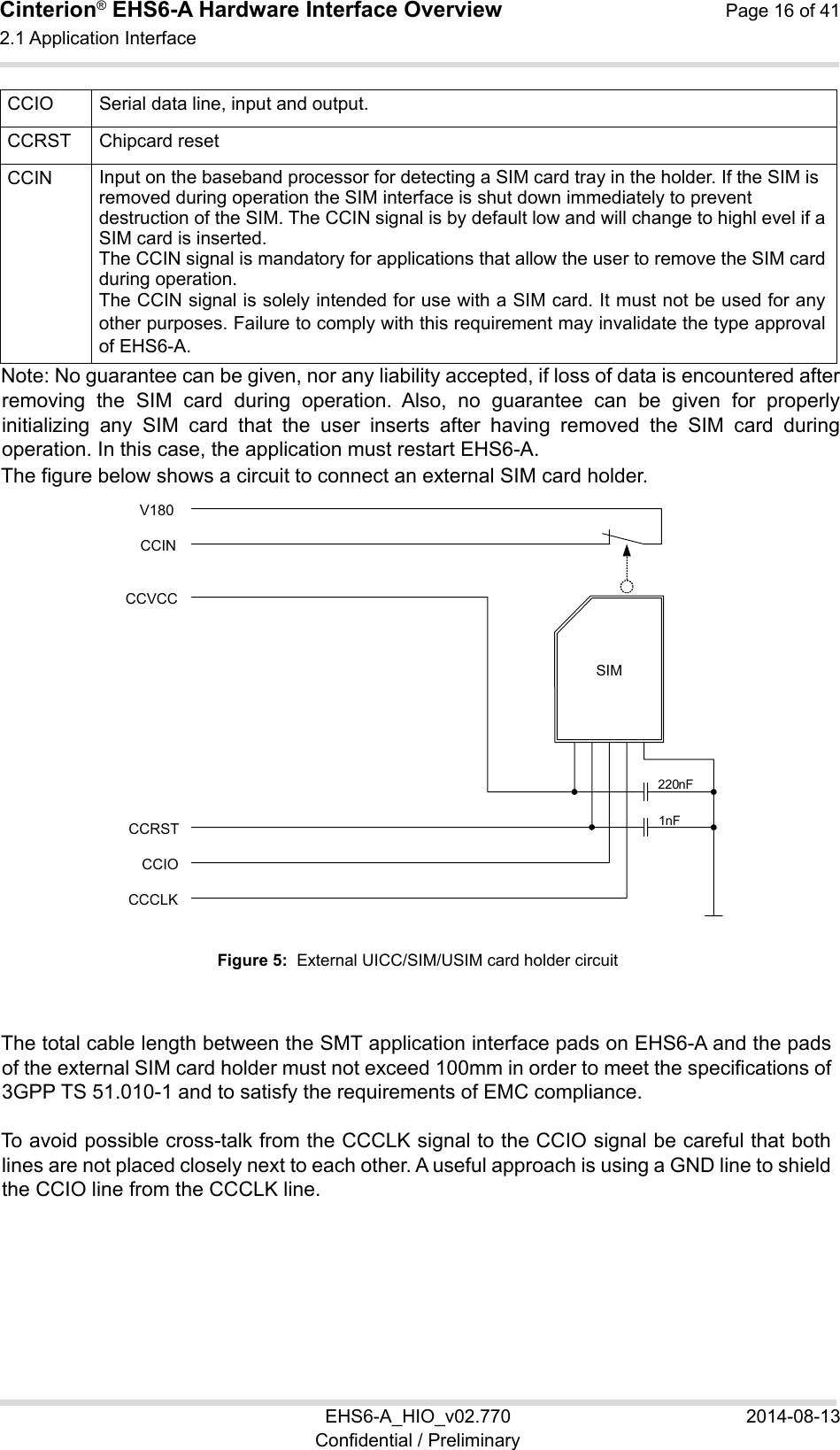
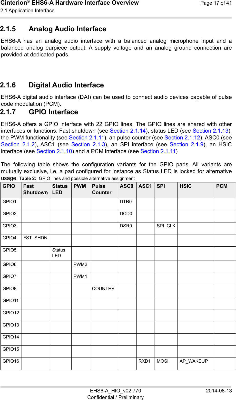
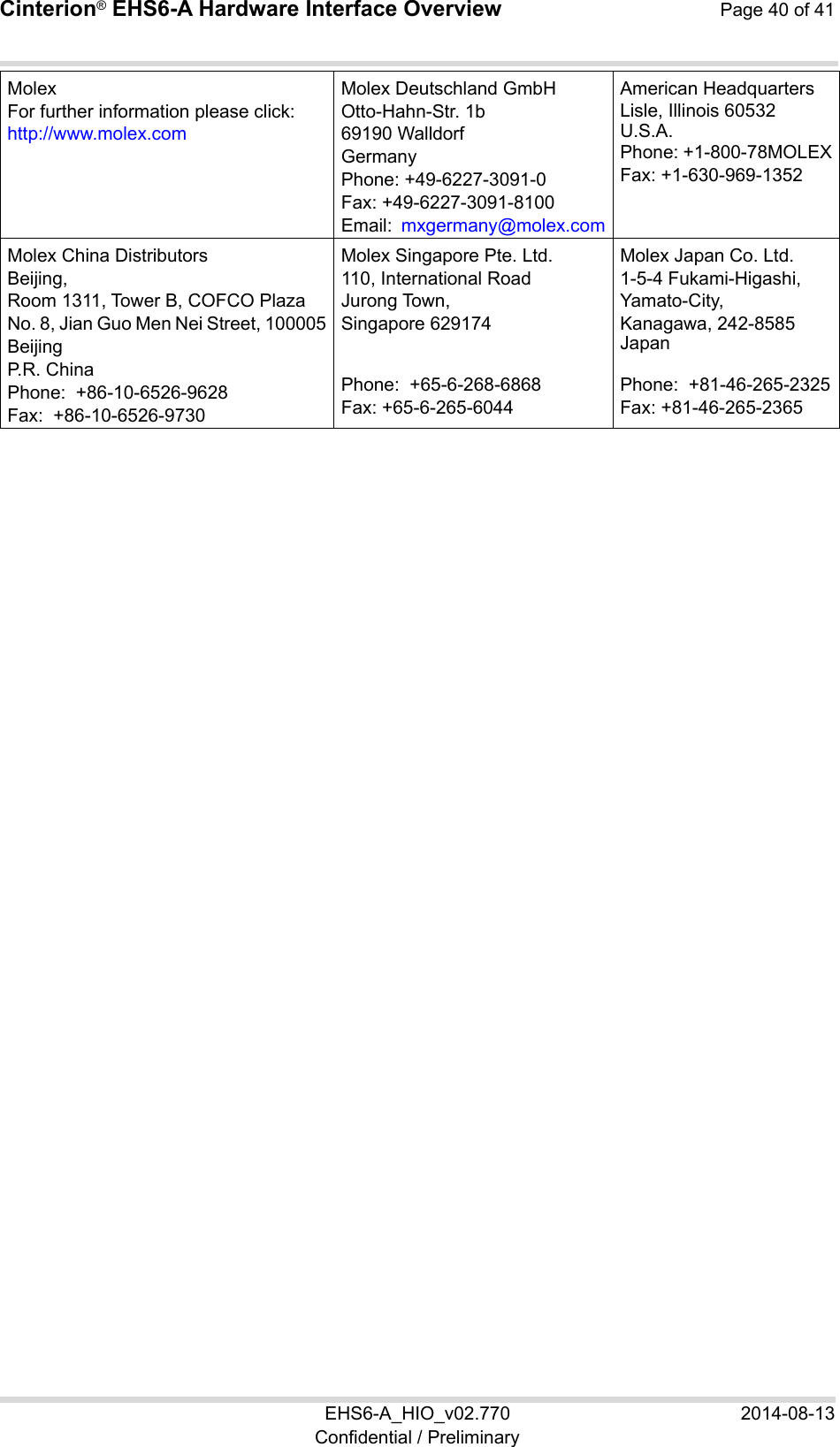
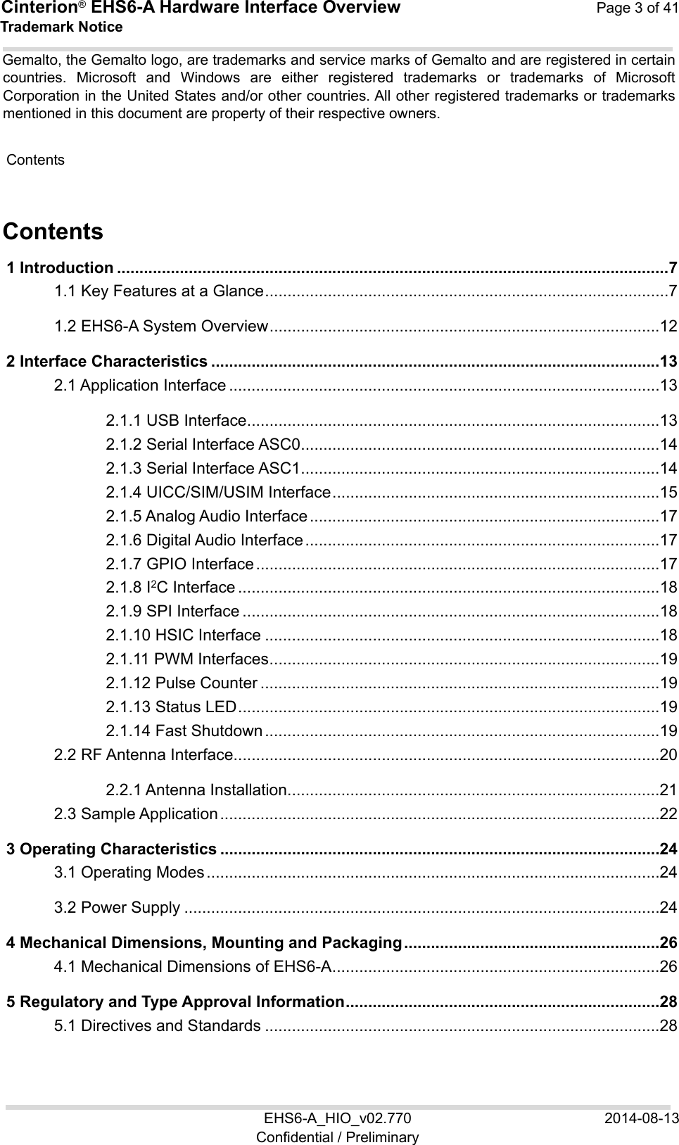
![Cinterion® EHS6-A Hardware Interface Overview Page 18 of 41 2.1 Application Interface 22 EHS6-A_HIO_v02.770 2014-08-13 Confidential / Preliminary GPIO17 TXD1 MISO HOST_ACTIVE GPIO18 RTS1 CP_WAKEUP GPIO19 CTS1 SPI_CS SUSPEND GPIO20 TXDDAIGPIO21 RXDDAIGPIO22 TFSDAIGPIO23 SCLKGPIO24 RING0 After startup, the above mentioned alternative GPIO line assignments can be configured using AT commands (see [1]). The configuration is non-volatile and available after module restart. 2.1.8 I2C Interface I2C is a serial, 8-bit oriented data transfer bus for bit rates up to 400kbps in Fast mode. It consists of two lines, the serial data line I2CDAT and the serial clock line I2CCLK. The module acts as a single master device, e.g. the clock I2CCLK is driven by the module. I2CDAT is a bi-directional line. Each device connected to the bus is software addressable by a unique 7-bit address, and simple master/slave relationships exist at all times. The module operates as mastertransmitter or as master-receiver. The customer application transmits or receives data only on request of the module. The I2C interface can be powered via the V180 line of EHS6-A. If connected to the V180 line, the I2C interface will properly shut down when the module enters the Power Down mode. Note: Good care should be taken when creating the PCB layout of the host application: The traces of I2CCLK and I2CDAT should be equal in length and as short as possible. 2.1.9 SPI Interface Four EHS6-A GPIO interface lines can be configured as Serial Peripheral Interface (SPI). The SPI is a synchronous serial interface for control and data transfer between EHS6-A and the external application. Only one application can be connected to the SPI and the interface supports only master mode. The transmission rates are up to 6.5Mbit/s. The SPI interface comprises the two data lines MOSI and MISO, the clock line SPI_CLK a well as the chip select line SPI_CS. 2.1.10 HSIC Interface The (USB) High Speed Inter Chip Interface can be used between the module and an external application processor and is compliant to the High Speed USB 2.0 interface with 480Mbit/s. The maximum distance between module processor and external application processor should not exceed 100mm.](https://usermanual.wiki/THALES-DIS-AlS-Deutschland/EHS6-A.EHS6-A-User-Manual-Rev-2/User-Guide-2388095-Page-18.png)
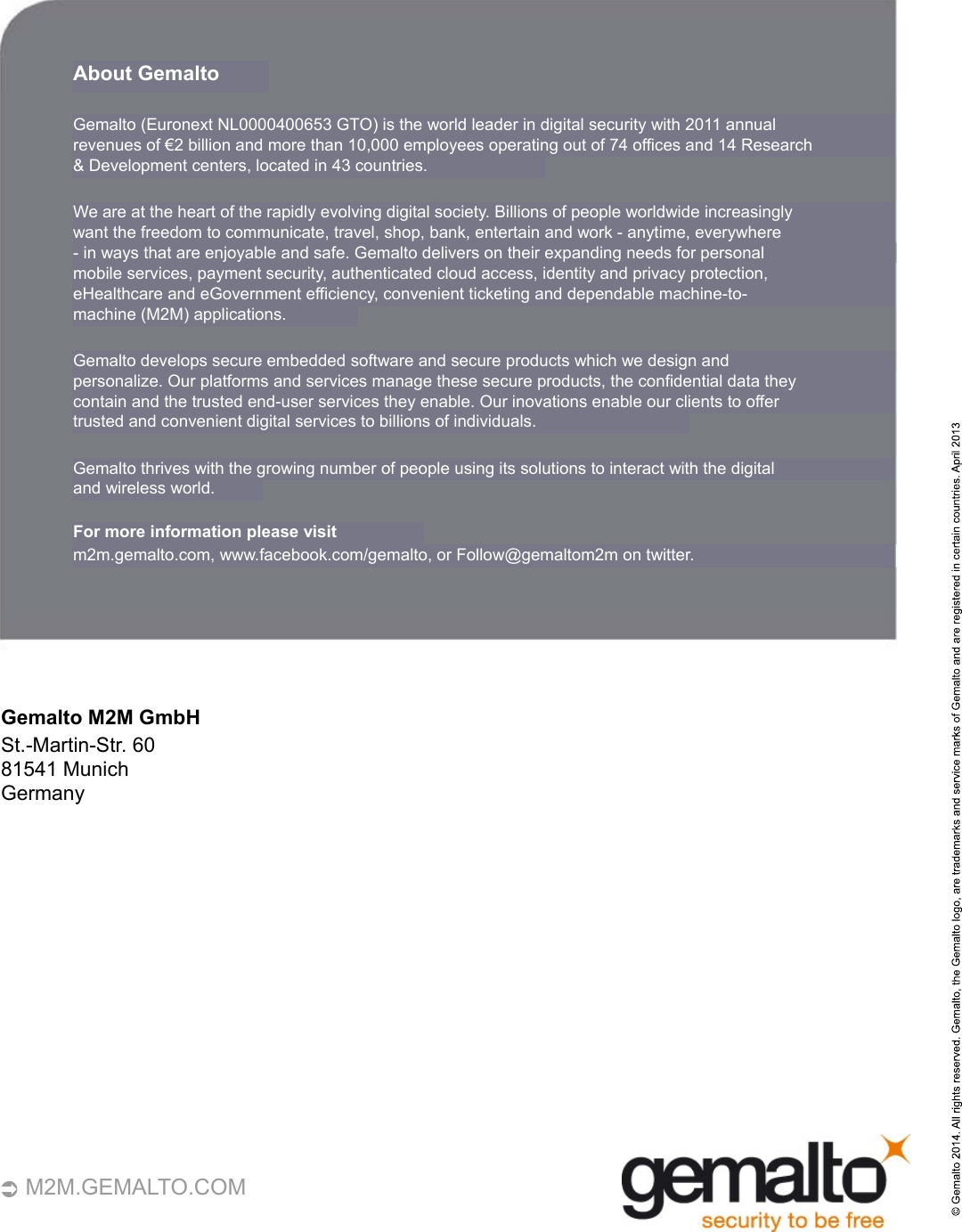
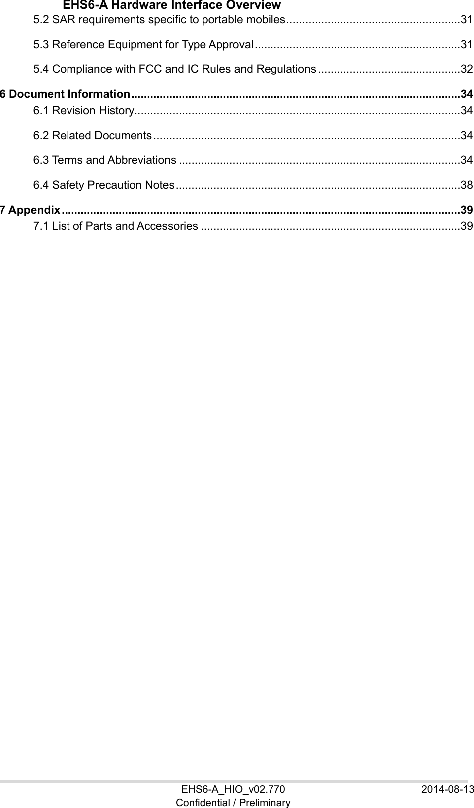
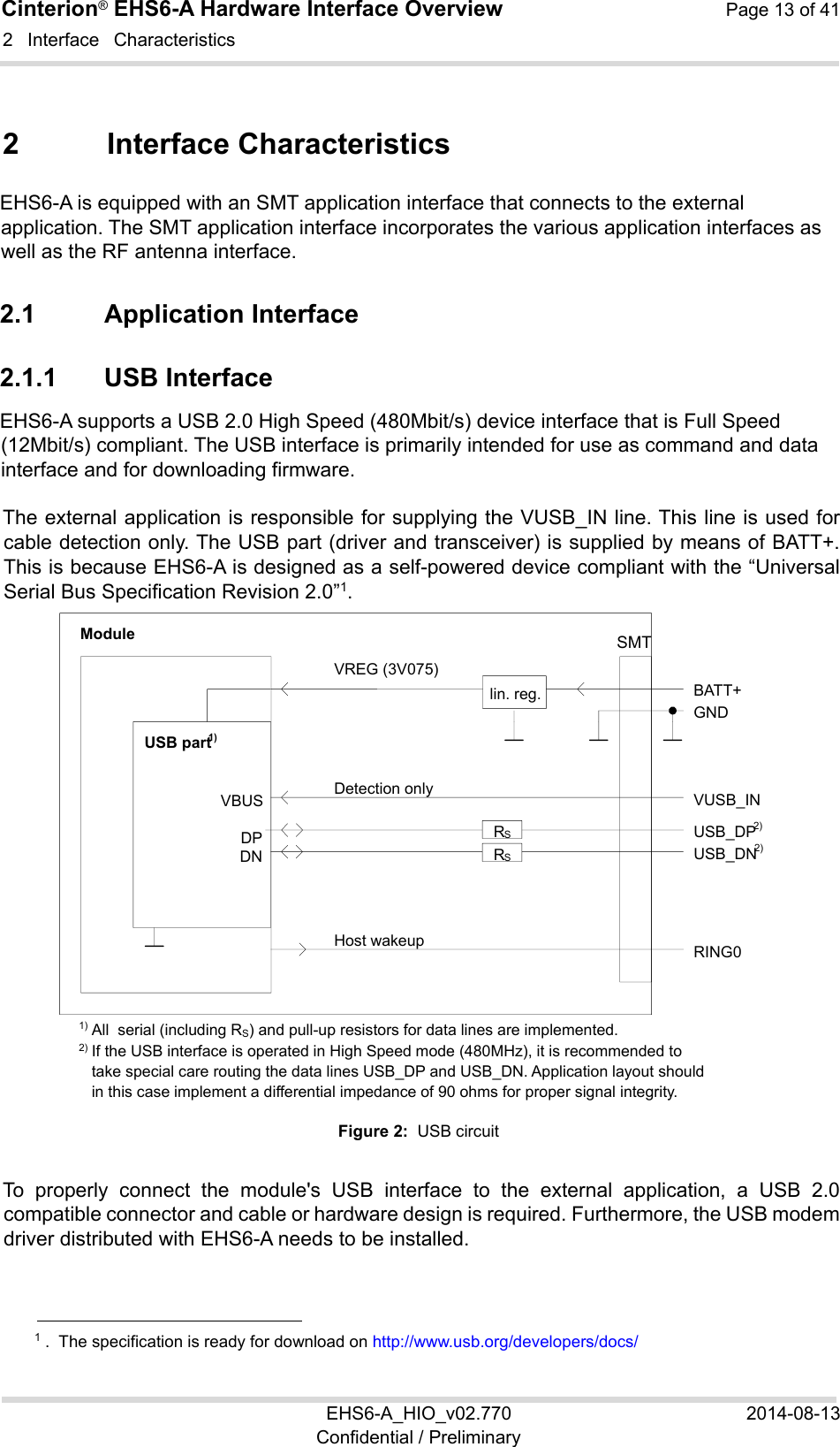
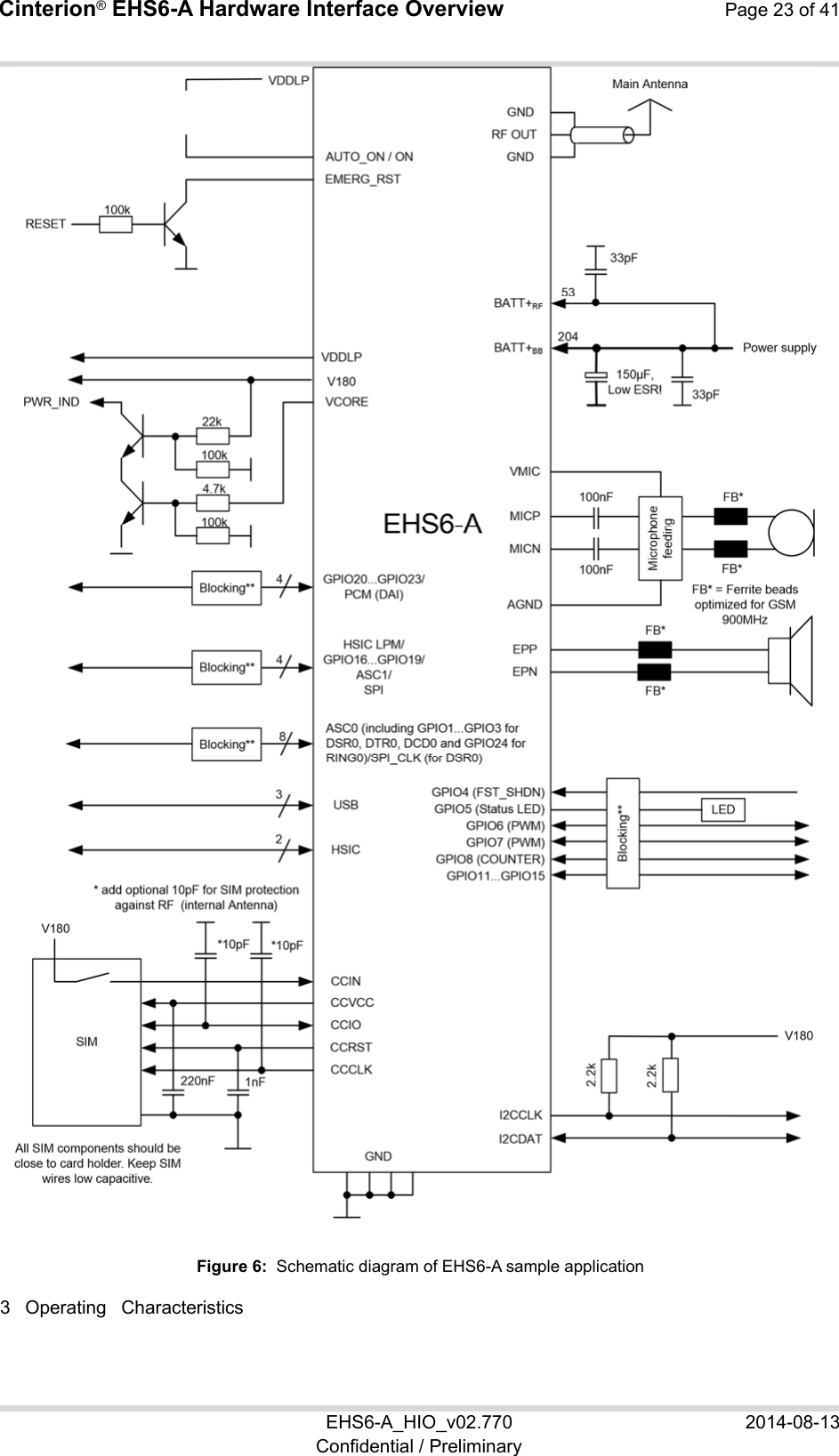
![Cinterion® EHS6-A Hardware Interface Overview Page 22 of 41 EHS6-A_HIO_v02.770 2014-08-13 Confidential / Preliminary 2.3 Sample Application 22 2.3 Sample Application Figure 6 shows a typical example of how to integrate a EHS6-A module with an application. Usage of the various host interfaces depends on the desired features of the application. The analog audio interface demonstrates the balanced connection of microphone and earpiece. This solution is particularly well suited for internal transducers. Because of the very low power consumption design, current flowing from any other source into the module circuit must be avoided, for example reverse current from high state external control lines. Therefore, the controlling application must be designed to prevent reverse current flow. Otherwise there is the risk of undefined states of the module during startup and shutdown or even of damaging the module. Because of the high RF field density inside the module, it cannot be guaranteed that no self interference might occur, depending on frequency and the applications grounding concept. The potential interferers may be minimized by placing small capacitors (47pF) at suspected lines (e.g. RXD0, RXT0, VDDLP, and ON). While developing SMT applications it is strongly recommended to provide test points for certain signals, i.e., lines to and from the module - for debug and/or test purposes. The SMT application should allow for an easy access to these signals. For details on how to implement test points see [3]. The EMC measures are best practice recommendations. In fact, an adequate EMC strategy for an individual application is very much determined by the overall layout and, especially, the position of components. For example, mounting the internal acoustic transducers directly on the PCB eliminates the need to use the ferrite beads shown in the sample schematic. Note: EHS6-A is not intended for use with cables longer than 3m. Disclaimer No warranty, either stated or implied, is provided on the sample schematic diagram shown in Figure 6 and the information detailed in this section. As functionality and compliance with national regulations depend to a great amount on the used electronic components and the individual application layout manufacturers are required to ensure adequate design and operating safeguards for their products using EHS6-A modules. 2.3 Sample Application 22](https://usermanual.wiki/THALES-DIS-AlS-Deutschland/EHS6-A.EHS6-A-User-Manual-Rev-2/User-Guide-2388095-Page-22.png)
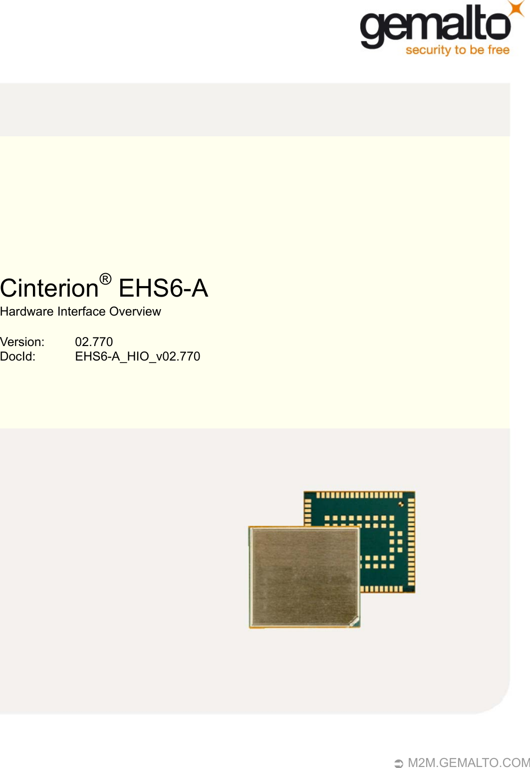
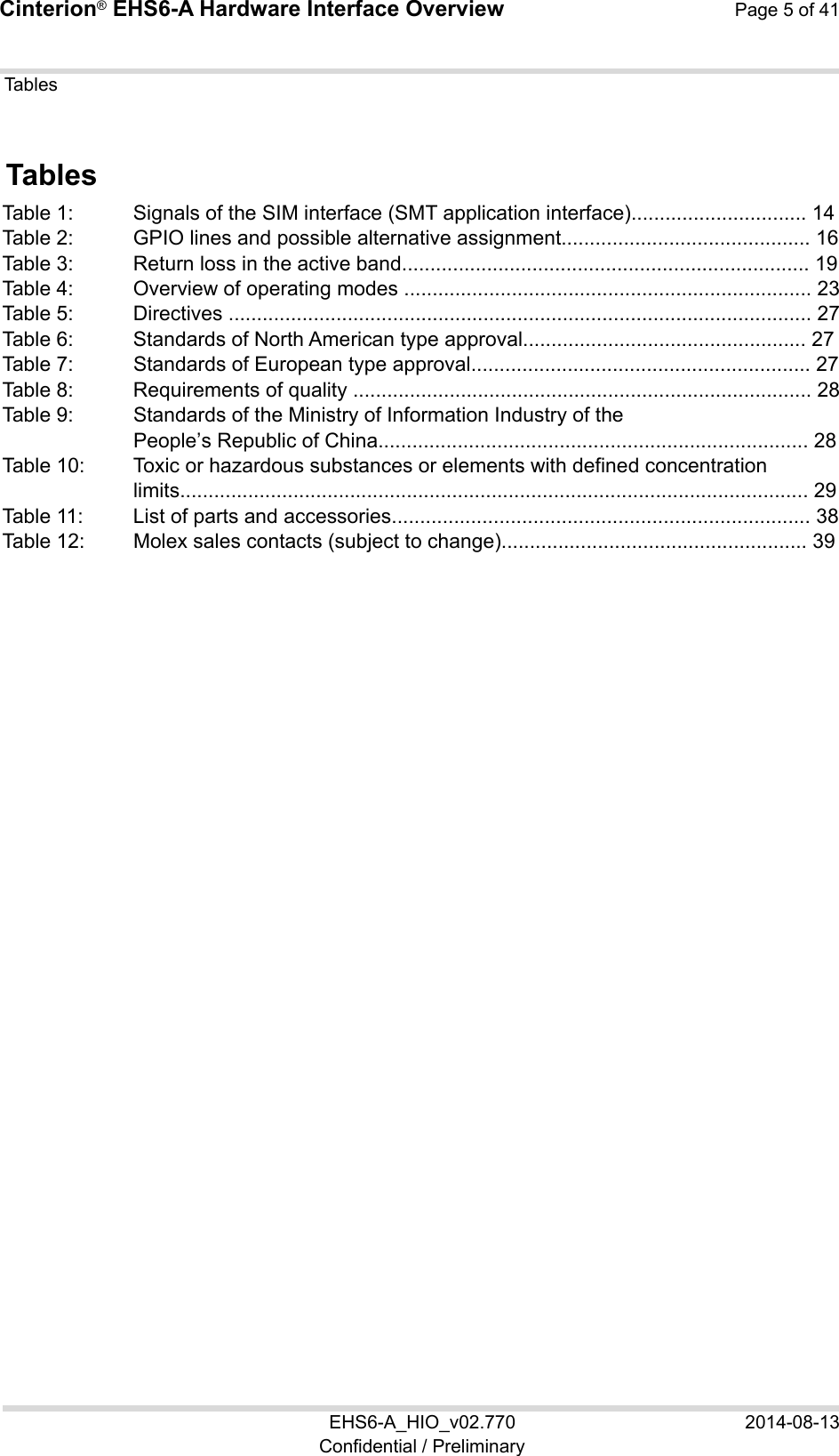
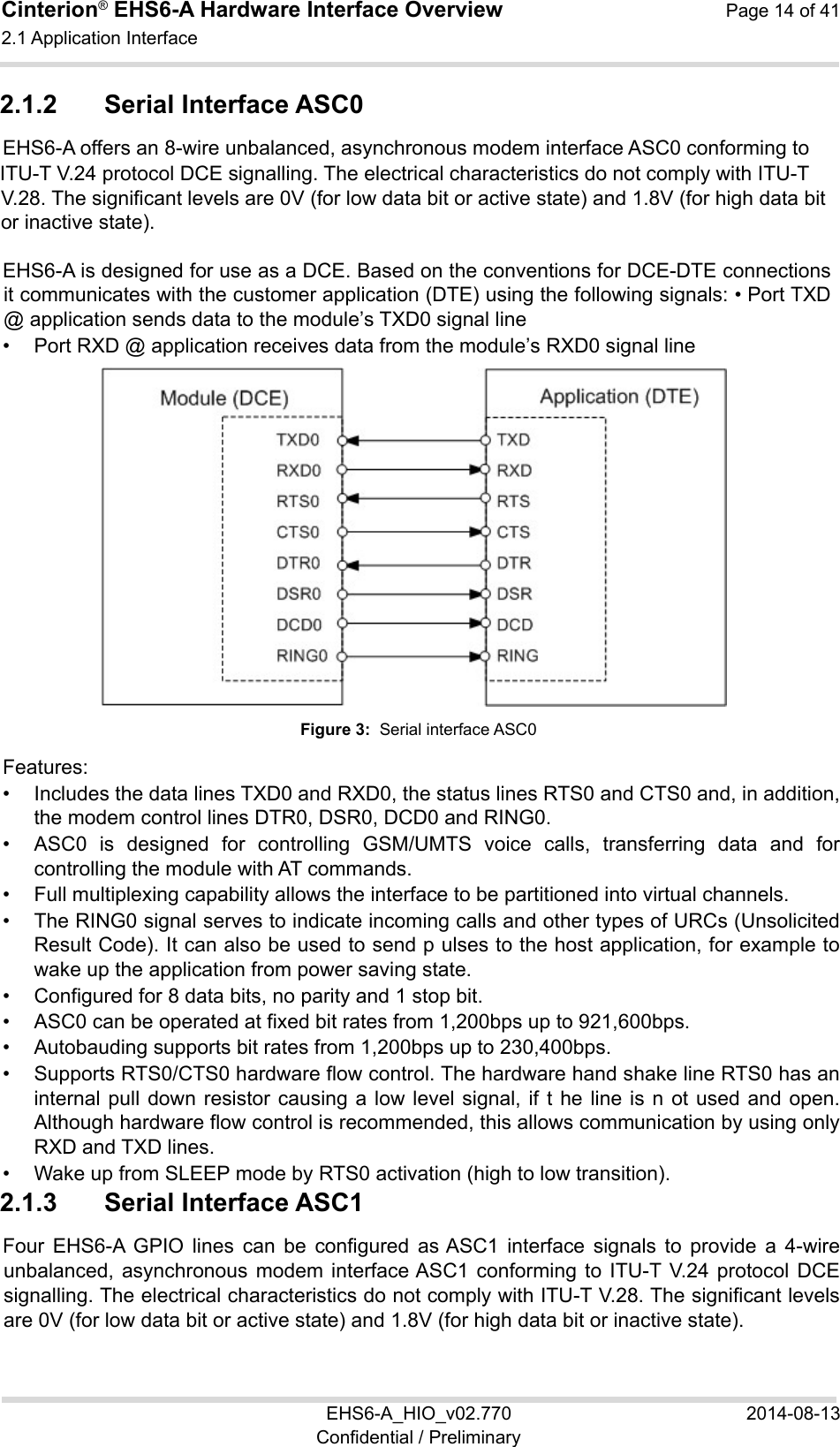
![Cinterion® EHS6-A Hardware Interface Overview Page 24 of 41 EHS6-A_HIO_v02.770 2014-08-13 Confidential / Preliminary 3 Operating Characteristics 3.1 Operating Modes The table below briefly summarizes the various operating modes referred to throughout the document. Table 4: Overview of operating modes Mode Function Normal operation GSM / GPRS / UMTS / HSPA SLEEP Power saving set automatically when no call is in progress and the USB connection is suspended by host or not present and no active communication via ASC0. GSM / GPRS / UMTS / HSPA IDLE Power saving disabled or an USB connection not suspended, but no call in progress. GSM TALK/ GSM DATA Connection between two subscribers is in progress. Power consumption depends on the GSM network coverage and several connection settings (e.g. DTX off/on, FR/EFR/HR, hopping sequences and antenna connection). The following applies when power is to be measured in TALK_GSM mode: DTX off, FR and no frequency hopping. GPRS DATA GPRS data transfer in progress. Power consumption depends on network settings (e.g. power control level), uplink / downlink data rates and GPRS configuration (e.g. used multislot settings). EGPRS DATA EGPRS data transfer in progress. Power consumption depends on network settings (e.g. power control level), uplink / downlink data rates and EGPRS configuration (e.g. used multislot settings). UMTS TALK/ UMTS DATA UMTS data transfer in progress. Power consumption depends on network settings (e.g. TPC Pattern) and data transfer rate. HSPA DATA HSPA data transfer in progress. Power consumption depends on network settings (e.g. TPC Pattern) and data transfer rate. Power Down Normal shutdown after sending the power down command. Only a voltage regulator is active for powering the RTC. Software is not active. Interfaces are not accessible. Operating voltage remains applied. Airplane mode Airplane mode shuts down the radio part of the module, causes the module to log off from the GSM/GPRS network and disables all AT commands whose execution requires a radio connection. Airplane mode can be controlled by AT command (see [1]). 3.2 Power Supply 24 3.2 Power Supply EHS6-A needs to be connected to a power supply at the SMT application interface - 2 lines BATT+, and GND. There are two separate voltage domains for BATT+: • BATT+BB with a line for the general power management. • BATT+RF with a line for the GSM power amplifier supply.](https://usermanual.wiki/THALES-DIS-AlS-Deutschland/EHS6-A.EHS6-A-User-Manual-Rev-2/User-Guide-2388095-Page-24.png)
![Cinterion® EHS6-A Hardware Interface Overview Page 34 of 41 EHS6-A_HIO_v02.770 2014-08-13 Confidential / Preliminary 6 Document Information 6.1 Revision History New document: "Cinterion® EHS6-A Hardware Interface Overview" Version 02.770 Chapter What is new -- Initial document setup. 6.2 Related Documents [1] EHS6-A AT Command Set [2] EHS6-A Release Note [3] Application Note 48: SMT Module Integration [4] Application Note 40: Thermal Solutions [5] Universal Serial Bus Specification Revision 2.0, April 27, 2000 6.3 Terms and Abbreviations Abbreviation Description ADC Analog-to-digital converterAGC Automatic Gain ControlANSI American National Standards InstituteARFCN Absolute Radio Frequency Channel NumberARP Antenna Reference PointASC0/ASC1 Asynchronous Controller. Abbreviations used for first and second serial interface of EHS6-A B Thermistor Constant BER Bit Error Rate BTS Base Transceiver StationCB or CBM Cell Broadcast MessageCE Conformité Européene (European Conformity)CHAP Challenge Handshake Authentication ProtocolCPU Central Processing UnitCS Coding Scheme CSD Circuit Switched Data CTS Clear to Send](https://usermanual.wiki/THALES-DIS-AlS-Deutschland/EHS6-A.EHS6-A-User-Manual-Rev-2/User-Guide-2388095-Page-34.png)