THALES DIS AlS Deutschland ELS31-V LTE Module User Manual hid
Gemalto M2M GmbH LTE Module hid
UserManual.wiki
>
THALES DIS AlS Deutschland
>
ELS31 V User Manual
User Manual
Navigation menu
Upload a User Manual
Namespaces
Wiki Guide
HTML
PDF
Info
Views
User Manual
Discussion / Help
Navigation
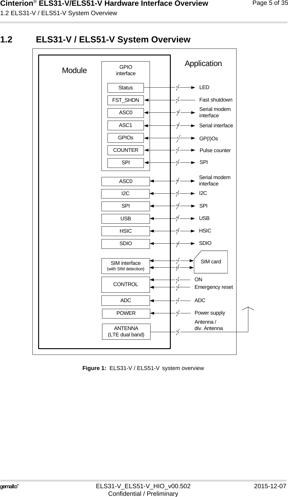
![Cinterion® ELS31-V/ELS51-V Hardware Interface Overview1.1 Key Features at a Glance5ELS31-V_ELS51-V_HIO_v00.502 2015-12-07Confidential / PreliminaryPage 3 of 35InterfacesModule interface Surface mount device with solderable connection pads (SMT application interface). Land grid array (LGA) technology ensures high solder joint reli-ability and allows the use of an optional module mounting socket.For more information on how to integrate SMT modules see also [4]. This application note comprises chapters on module mounting and application layout issues as well as on SMT application development equipment.USB USB 2.0 High Speed (480Mbit/s) device interface, Full Speed (12Mbit/s)compliant2 serial interfaces ASC0:• 8-wire modem interface with status and control lines, unbalanced, asyn-chronous• Default baud rate: 115,200 baud• Adjustable baud rates: 1,200 to 921,600, no autobauding support• Supports RTS0/CTS0 hardware flow control. • indication of incoming data/SMS on RING0 (can be used to wake uphost from power down modes)ELS51-V only:ASC1 (shared with GPIO lines):• 4-wire, unbalanced asynchronous interface• Default baud rate: 115,200 baud• Adjustable baud rates: 1,200bps to 921,600bps• Supports RTS1/CTS1 hardware flow controlUICC interface Supported SIM/USIM cards: 3V, 1.8VEmbedded UICC Module is prepared for an embedded UICCGPIO interface 20 pads of the application interface programmable as GPIO pads (17) or GPO pads (3):GP(I)Os can be configured as COUNTER, FST_SHDN, ASC0, ASC1, and SPI signal linesProgramming is done via AT commandsI2C interface Supports I2C serial interfaceSPI interface Supports SPI interfaceSDIO ELS51-V only:4 wire interface.HSIC ELS51-V only:High Speed Interchip Communication interface. ADC Analog-to-Digital Converter with one unbalanced analog input.Digitial audio interface Hardware prepared for future use.Antenna interface pads 50 LTE main antenna, 50LTE diversity antennaFeature Implementation](https://usermanual.wiki/THALES-DIS-AlS-Deutschland/ELS31-V/User-Guide-2843651-Page-7.png)
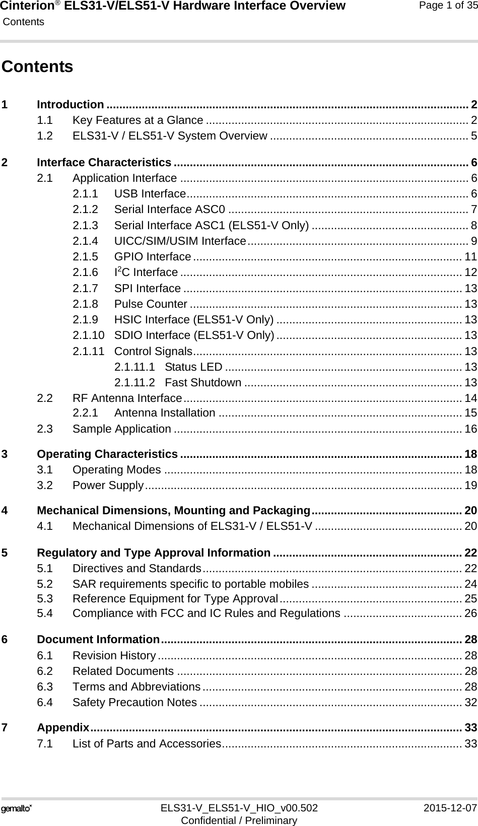
![Cinterion® ELS31-V/ELS51-V Hardware Interface Overview2.1 Application Interface17ELS31-V_ELS51-V_HIO_v00.502 2015-12-07Confidential / PreliminaryPage 11 of 352.1.5 GPIO InterfaceELS31-V / ELS51-V offers a GPIO interface with 17 GPIO and 3 GPO lines. The lines areshared with other interfaces or functions: Fast shutdown (see Section 2.1.11.2), status LED(see Section 2.1.11.1), a pulse counter (see Section 2.1.8), ASC0 (see Section 2.1.2), ASC1(see Section 2.1.3), SPI (see Section 2.1.7), and HSIC (see Section 2.1.9).The following table shows the configuration variants for the GPIO pads. All variants are mutu-ally exclusive, i.e. a pad configured for instance as Status LED is locked for alternative usage.After startup, the above mentioned alternative GPIO line assignments can be configured usingAT commands (see [1]). The configuration is non-volatile and available after module restart.Notes:• GPO5, GPO23 and GPO26 are GPOs only.Table 2: GPIO lines and possible alternative assignmentGPIO Fast Shutdown Status LED Pulse Counter ASC0 ASC1 SPI HSICGPIO1 DTR0GPIO2 DCD0GPIO3 DSR0GPIO4 FST_SHDNGPO5 LEDGPIO6GPIO7GPIO8 COUNTERGPIO16 RXD1 AP_WAKEUPGPIO17 TXD1 HOST_ACTIVEGPIO18 RTS1 CP_WAKEUPGPIO19 CTS1 SUSPENDGPIO20GPIO21GPIO22GPO23GPIO24 RING0GPIO25GPO26 SPI_CS1GPIO27 SPI_CS2](https://usermanual.wiki/THALES-DIS-AlS-Deutschland/ELS31-V/User-Guide-2843651-Page-15.png)
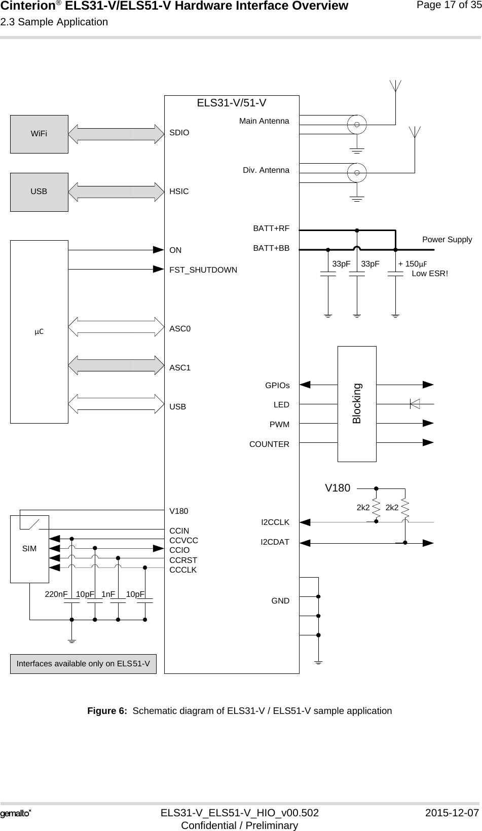
![Cinterion® ELS31-V/ELS51-V Hardware Interface Overview2.3 Sample Application17ELS31-V_ELS51-V_HIO_v00.502 2015-12-07Confidential / PreliminaryPage 16 of 352.3 Sample ApplicationFigure 6 shows a typical example of how to integrate a ELS31-V / ELS51-V module with anapplication. Usage of the various host interfaces depends on the desired features of the appli-cation.Because of the high RF field density inside the module, it cannot be guaranteed that no selfinterference might occur, depending on frequency and the applications grounding concept. Thepotential interferers may be minimized by placing small capacitors (47pF) at suspected lines(e.g. RXD0, VDDLP, and ON). While developing SMT applications it is strongly recommended to provide test pointsfor certain signals, i.e., lines to and from the module - for debug and/or test purposes.The SMT application should allow for an easy access to these signals. For details onhow to implement test points see [4].The EMC measures are best practice recommendations. In fact, an adequate EMC strategy foran individual application is very much determined by the overall layout and, especially, the po-sition of components. For example, mounting the internal acoustic transducers directly on thePCB eliminates the need to use the ferrite beads shown in the sample schematic. Note: ELS31-V / ELS51-V is not intended for use with cables longer than 3m.DisclaimerNo warranty, either stated or implied, is provided on the sample schematic diagram shown inFigure 6 and the information detailed in this section. As functionality and compliance with na-tional regulations depend to a great amount on the used electronic components and the indi-vidual application layout manufacturers are required to ensure adequate design and operatingsafeguards for their products using ELS31-V / ELS51-V modules.](https://usermanual.wiki/THALES-DIS-AlS-Deutschland/ELS31-V/User-Guide-2843651-Page-20.png)
![Cinterion® ELS31-V/ELS51-V Hardware Interface Overview3 Operating Characteristics19ELS31-V_ELS51-V_HIO_v00.502 2015-12-07Confidential / PreliminaryPage 18 of 353 Operating Characteristics3.1 Operating ModesThe table below briefly summarizes the various operating modes referred to throughout the document. Table 4: Overview of operating modesMode FunctionNormal opera-tionLTE IDLE No data transfer is in progress and the USB connection is suspended by host (or is not present) and no active communication via ASC0/ASC1. In IDLE mode, the software can be active or in SLEEP state.LTE DATA LTE data transfer in progress. Power consumption depends on network settings and data transfer rate. Power Down Normal shutdown after sending the power down command. Software is not active. Inter-faces are not accessible. Operating voltage remains applied.Airplane mode Airplane mode shuts down the radio part of the module, causes the module to log off from the LTE network and disables all AT commands whose execution requires a radio connec-tion.Airplane mode can be controlled by AT command (see [1]).In Airplane mode, the software can be active or in SLEEP state.](https://usermanual.wiki/THALES-DIS-AlS-Deutschland/ELS31-V/User-Guide-2843651-Page-22.png)
![Cinterion® ELS31-V/ELS51-V Hardware Interface Overview6 Document Information32ELS31-V_ELS51-V_HIO_v00.502 2015-12-07Confidential / PreliminaryPage 28 of 356 Document Information6.1 Revision HistoryNew document: "Cinterion® ELS31-V/ELS51-V Hardware Interface Overview" v00.5026.2 Related Documents[1] ELS31-V / ELS51-V AT Command Set[2] ELS31-V / ELS51-V Release Note[3] Application Note 40: Thermal Solutions[4] Application Note 48: SMT Module Integration[5] Universal Serial Bus Specification Revision 2.0, April 27, 20006.3 Terms and AbbreviationsChapter What is new-- Initial document setup.Abbreviation DescriptionADC Analog-to-digital converterAGC Automatic Gain ControlANSI American National Standards InstituteARFCN Absolute Radio Frequency Channel NumberARP Antenna Reference PointASC0/ASC1 Asynchronous Controller. Abbreviations used for first and second serial interface of the modueB Thermistor ConstantBER Bit Error RateBTS Base Transceiver StationCB or CBM Cell Broadcast MessageCE Conformité Européene (European Conformity)CHAP Challenge Handshake Authentication ProtocolCPU Central Processing UnitCS Coding SchemeCSD Circuit Switched DataCTS Clear to SendDAC Digital-to-Analog Converter](https://usermanual.wiki/THALES-DIS-AlS-Deutschland/ELS31-V/User-Guide-2843651-Page-32.png)