THALES DIS AlS Deutschland EMS31-V Cinterion EMS31-V User Manual hid emsx1 v
Gemalto M2M GmbH Cinterion EMS31-V hid emsx1 v
UserManual.wiki
>
THALES DIS AlS Deutschland
>
EMS31 V User Manual
Users Manual
Navigation menu
Upload a User Manual
Namespaces
Wiki Guide
HTML
PDF
Info
Views
User Manual
Discussion / Help
Navigation
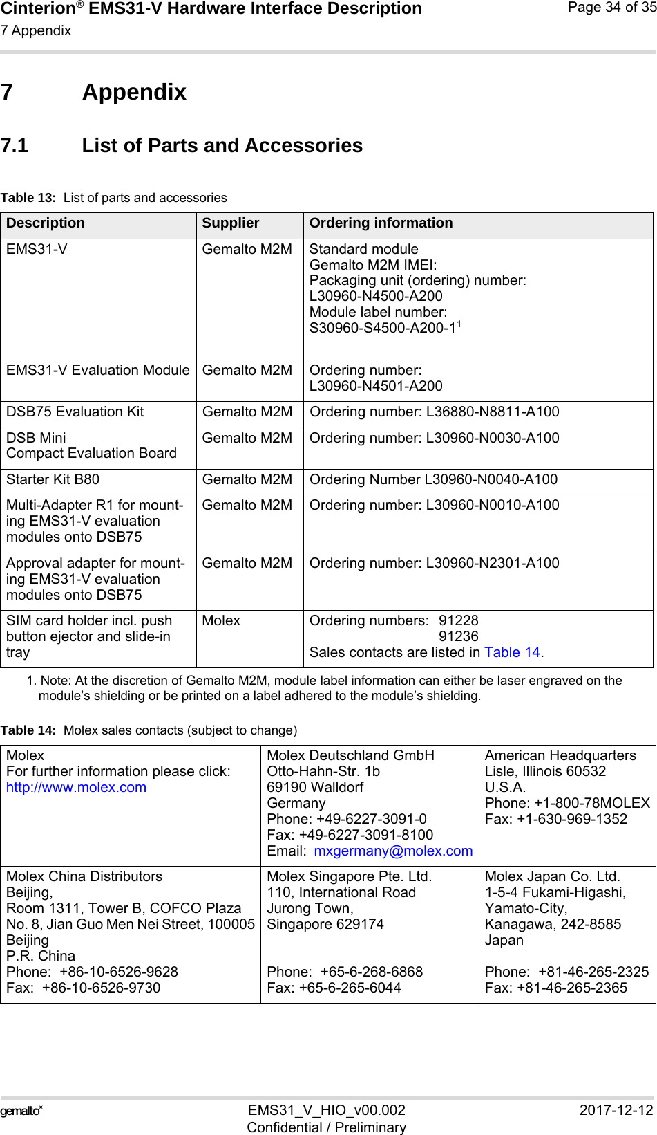
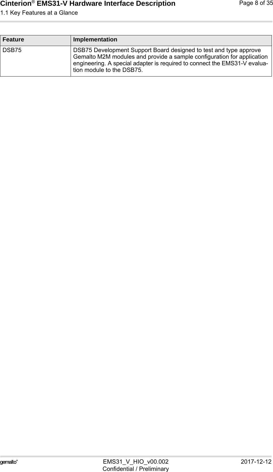
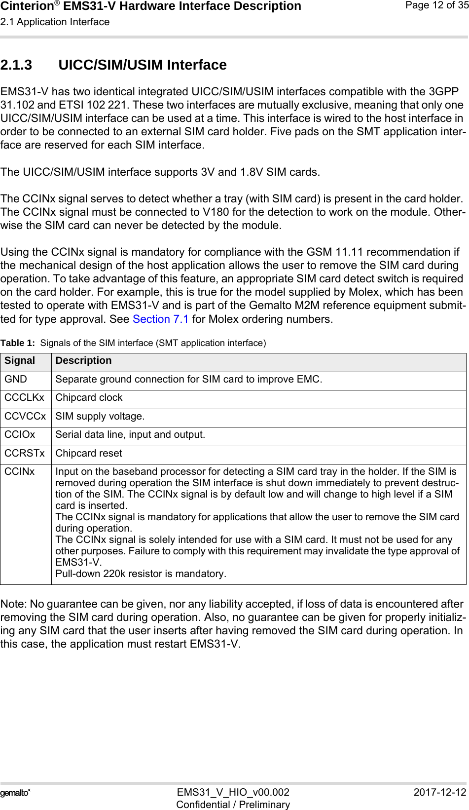
![Cinterion® EMS31-V Hardware Interface Description1.1 Key Features at a Glance9EMS31_V_HIO_v00.002 2017-12-12Confidential / PreliminaryPage 7 of 35InterfacesModule interface Surface mount device with solderable connection pads (SMT application interface). Land grid array (LGA) technology ensures high solder joint reli-ability and allows the use of an optional module mounting socket.For more information on how to integrate SMT modules see also [3]. Thisapplication note comprises chapters on module mounting and applicationlayout issues as well as on SMT application development equipment.2 serial interfaces ASC0:• 8-wire modem interface with status and control lines, unbalanced, asyn-chronous• Default baud rate: 115,200 baud• Adjustable baud rates: 1,200 to 3,686,400• Supports RTS0/CTS0 hardware flow control.•Indication of incoming data/SMS on RING0 (can be used to wake uphost from power down modes)ASC1 (shared with GPIO lines):• 4-wire, unbalanced asynchronous interface• Default baud rate: 115,200 baud• Adjustable baud rates: 1,200 to 3,686,400bps• Supports RTS1/CTS1 hardware flow controlUICC interface Supported SIM/USIM cards: 3V, 1.8VEmbedded UICC Module is hardware prepared for an embedded UICC (MIM)GPIO interface 20 pads of the application interface programmable as GPIO pads (17) or GPO pads (3):GP(I)Os can be configured as ASC0 andASC1 Programming is done via AT commandsSDIO EMS51 only:4 wire interface.HSIC EMS51 only:High Speed Interchip Communication interface. Digitial audio interface Hardware prepared for future use.Antenna interface pad 50Ω LTE antennaPower on/off, ResetPower on/off Switch-on by hardware signal ON Switch-off by AT command Automatic switch-off in case of critical temperature and voltage conditions Reset Orderly shutdown and reset by AT commandEvaluation kitEvaluation module EMS31-V module soldered onto a dedicated PCB that can be connected to an adapter in order to be mounted onto the DSB75.Feature Implementation](https://usermanual.wiki/THALES-DIS-AlS-Deutschland/EMS31-V/User-Guide-3710344-Page-7.png)
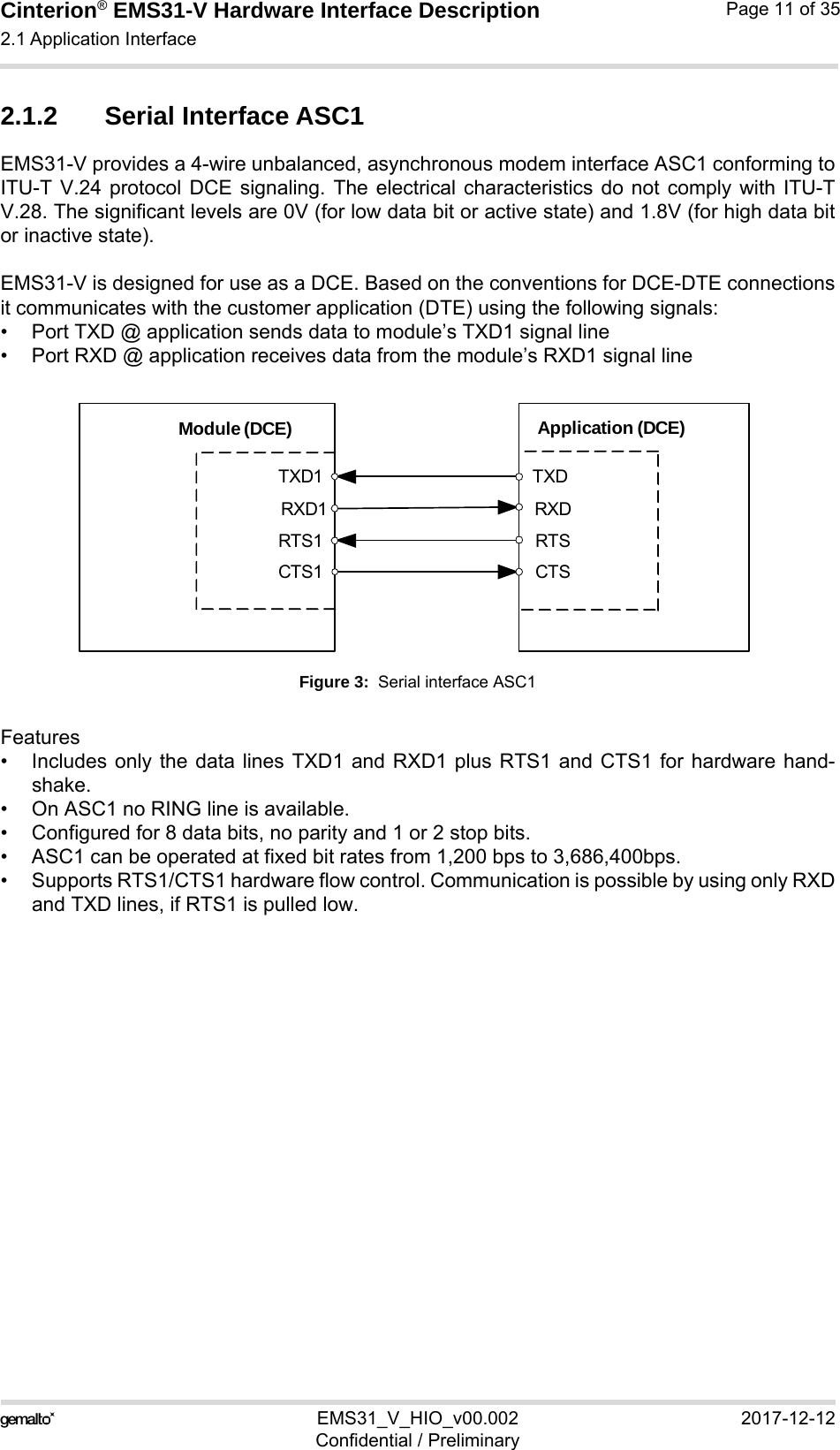
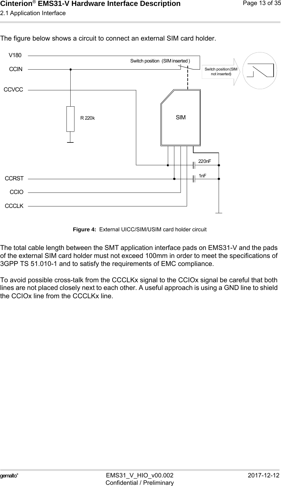
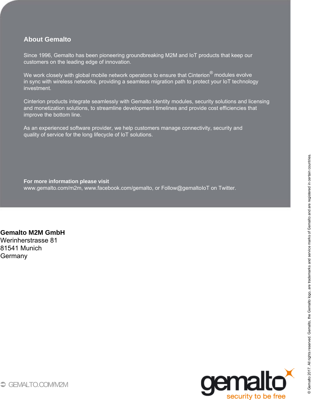
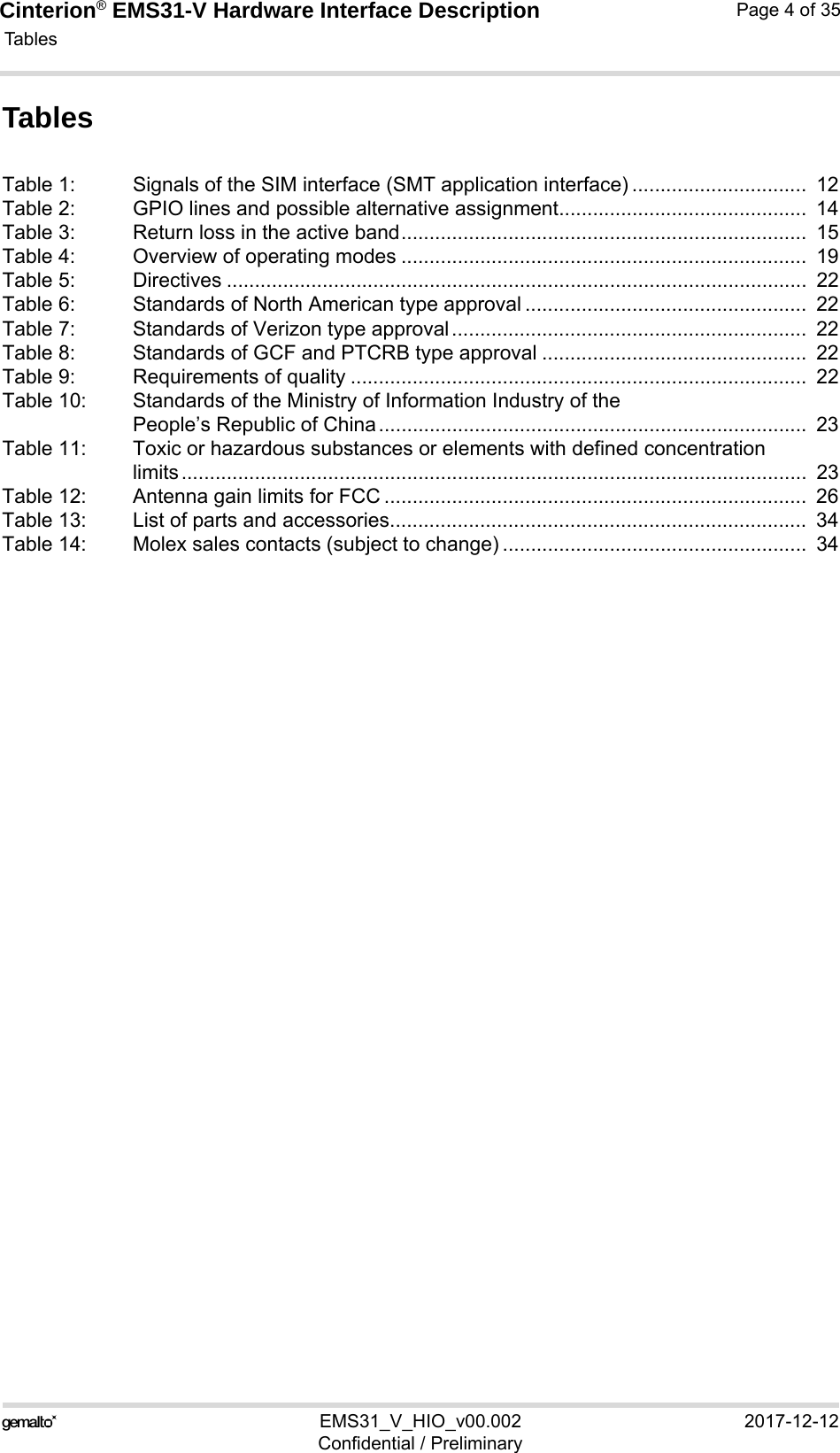
![Cinterion® EMS31-V Hardware Interface Description2.1 Application Interface18EMS31_V_HIO_v00.002 2017-12-12Confidential / PreliminaryPage 14 of 352.1.4 GPIO InterfaceEMS31-V offers a GPIO interface with 20 GPIO lines. The lines are shared with other interfacesor functions: ASC0 (see Section 2.1.1), ASC1 (see Section 2.1.2), The following table shows the configuration variants for the GPIO pads. All variants are mutu-ally exclusive, i.e. a pad configured for instance as ASC0 is locked for alternative usage.*) Note: The following features are not yet available with the current product release: GPIO, I2C, PulseCounter, PWM, FST_SHDN and SPI.After startup, the above mentioned alternative GPIO line assignments can be configured usingAT commands (see [1]). The configuration is non-volatile and available after module restart.Table 2: GPIO lines and possible alternative assignmentGPIO* Fast Shut-down*Status LED Pulse Counter* ASC0 ASC1 SPI* PWM* WAKEcapabilityGPIO1 DTR0 AvailableGPIO2 DCD0GPIO3 DSR0GPIO4 FST_SHDNGPO5 LEDGPIO6 PWM2GPIO7 PWM1GPIO8 COUNTER AvailableGPIO16 RXD1GPIO17 TXD1GPIO18 RTS1 AvailableGPIO19 CTS1GPIO20GPIO21GPIO22GPO23GPIO24 RING0GPIO25 AvailableGPO26 SPI_CS1GPIO27 SPI_CS2n/a RST0 Available](https://usermanual.wiki/THALES-DIS-AlS-Deutschland/EMS31-V/User-Guide-3710344-Page-14.png)
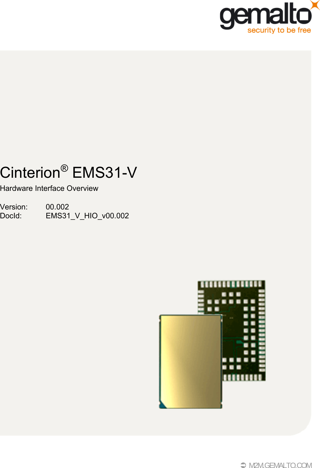
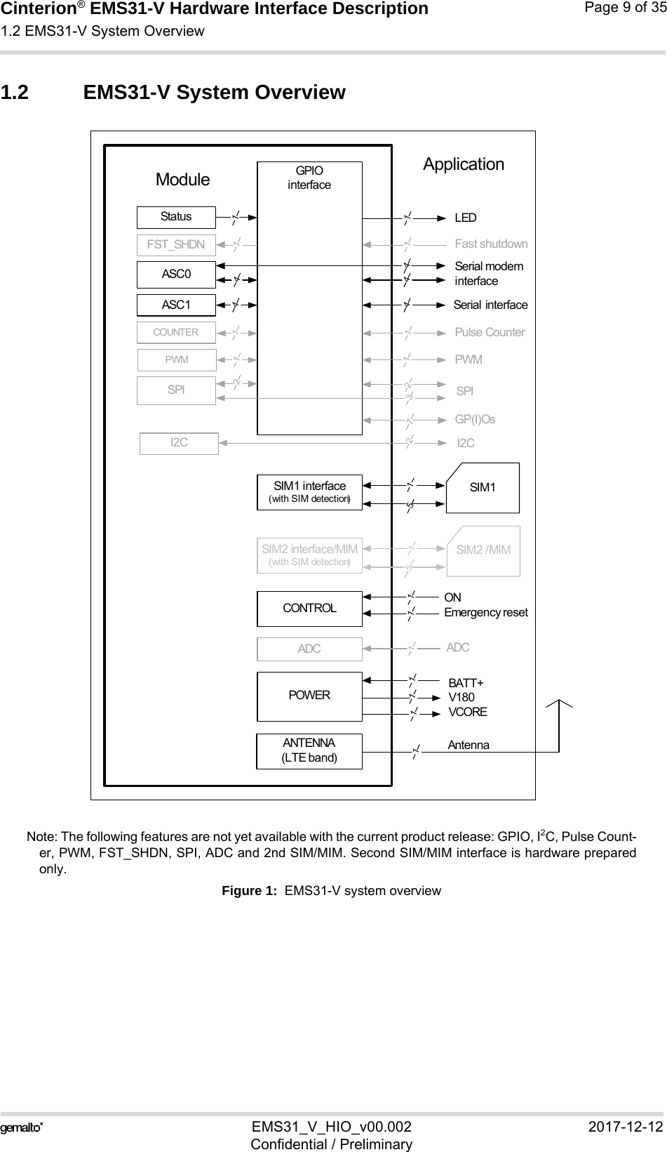
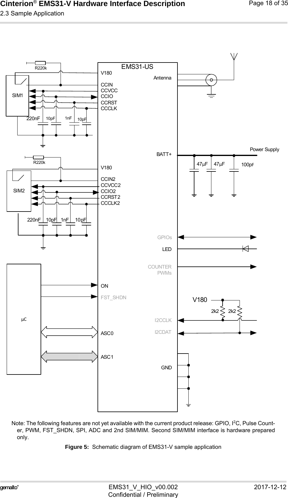
![Cinterion® EMS31-V Hardware Interface Description2.3 Sample Application18EMS31_V_HIO_v00.002 2017-12-12Confidential / PreliminaryPage 17 of 352.3 Sample ApplicationFigure 5 shows a typical example of how to integrate an EMS31-V module with an application.Usage of the various host interfaces depends on the desired features of the application.Because of the high RF field density inside the module, it cannot be guaranteed that no selfinterference might occur, depending on frequency and the applications grounding concept. Thepotential interferers may be minimized by placing small capacitors (47pF) at suspected lines(e.g. RXD0, or ON). While developing SMT applications it is strongly recommended to provide test pointsfor certain signals, i.e., lines to and from the module - for debug and/or test purposes.The SMT application should allow for an easy access to these signals. For details onhow to implement test points see [3].The EMC measures are best practice recommendations. In fact, an adequate EMC strategy foran individual application is very much determined by the overall layout and, especially, the po-sition of components.Note: EMS31-V is not intended for use with cables longer than 3m.Disclaimer: No warranty, either stated or implied, is provided on the sample schematic diagramshown in Figure 5 and the information detailed in this section. As functionality and compliancewith national regulations depend to a great amount on the used electronic components and theindividual application layout manufacturers are required to ensure adequate design and oper-ating safeguards for their products using EMS31-V module.](https://usermanual.wiki/THALES-DIS-AlS-Deutschland/EMS31-V/User-Guide-3710344-Page-17.png)
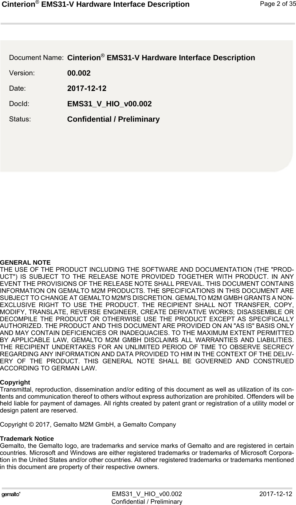
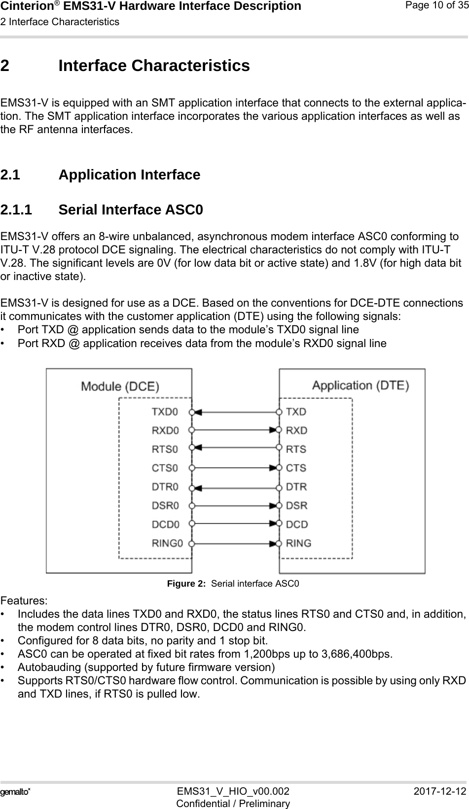
![Cinterion® EMS31-V Hardware Interface Description3 Operating Characteristics19EMS31_V_HIO_v00.002 2017-12-12Confidential / PreliminaryPage 19 of 353 Operating Characteristics3.1 Operating ModesThe table below briefly summarizes the various operating modes referred to throughout thedocument. 3.2 Power SupplyThe power supply of EMS31-V has to be a single voltage source at BATT+. It must be able toprovide the current for all operation modes of the module.All the key functions for supplying power to the device are handled by the power managementsection of the analog controller. This IC provides the following features:• Stabilizes the supply voltages for the baseband using low drop linear voltage regulators anda DC-DC step down switching regulator.• Switches the module's power voltages for the power-up and -down procedures.• SIM switch to provide SIM power supply.Table 4: Overview of operating modesMode FunctionNormal opera-tionActive TX LTE data transfer in progress. Power consumption depends on network settings, data transfer rate and radio conditions.No data transfer is in progress and no active communication via ASC0/ ASC1. IDLE No data transfer is in progress. The LTE part of the device can be in LTE DRX, LTE eDRX or LTE PSM mode. Activity on ASC0 /ASC1 inter-faces can be present. Power consumption depends on the LTE power saving mode and its parameters and on the activity on the ASC inter-faces.Sleep The module is in low power consumption state. There is no activity inside the module but module preserves the state in which it was before entering the sleep mode, including the electrical states of the GPIOs. The module will enter sleep state only when the LTE part of the module is in LTE DRX, LTE eDRX or LTE PSM mode or if it is in airplane mode. To allow sleep mode the host application shall indicate via RTS lines that it has no intention to send data.Power DownNormal shutdown after sending the power down command. Software is not active. Inter-faces are not accessible. Operating voltage remains applied.Airplane modeAirplane mode shuts down the radio part of the module, causes the module to log off from the LTE network and disables all AT commands whose execution requires a radio connec-tion.Airplane mode can be controlled by AT command (see [1]).Sleep mode can be entered when airplane mode is enabled.](https://usermanual.wiki/THALES-DIS-AlS-Deutschland/EMS31-V/User-Guide-3710344-Page-19.png)
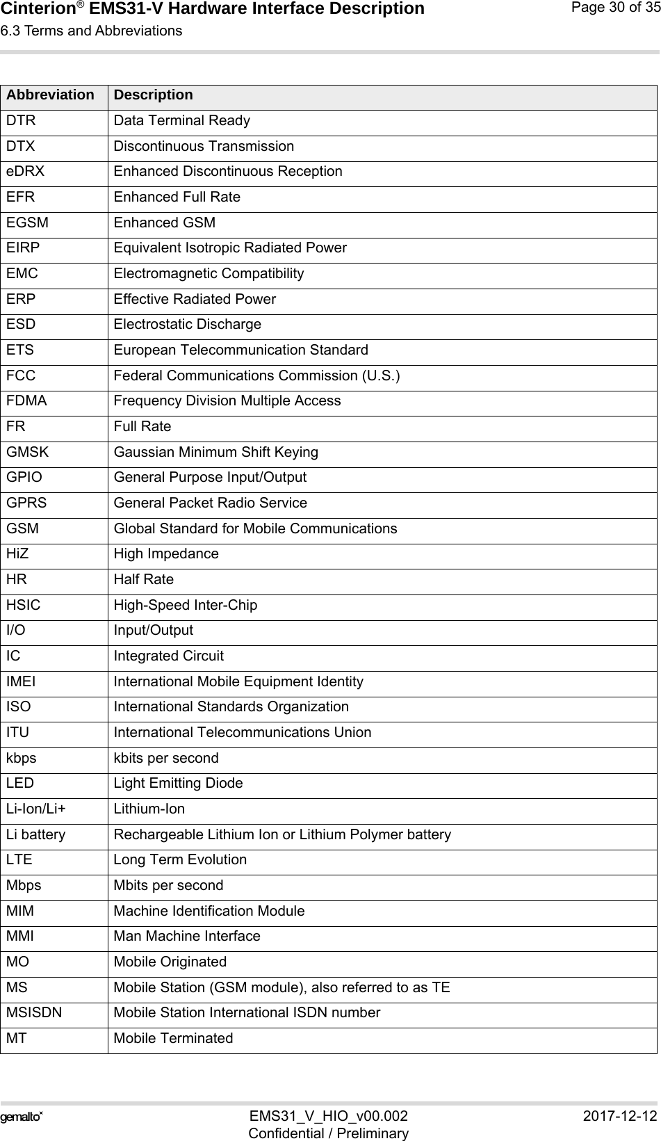
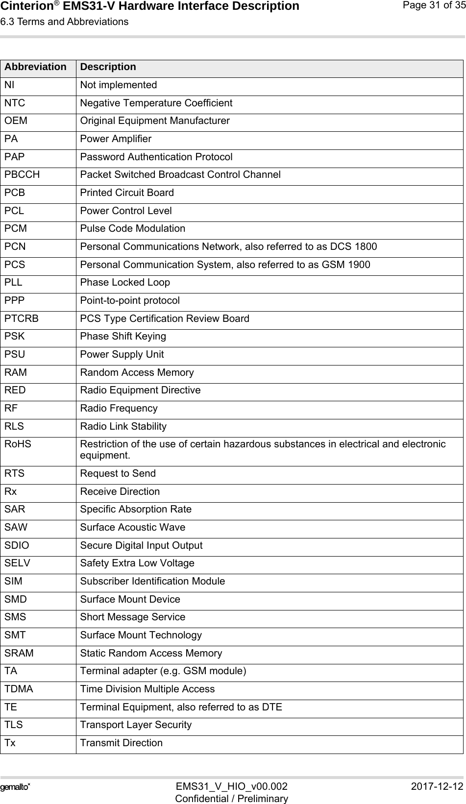
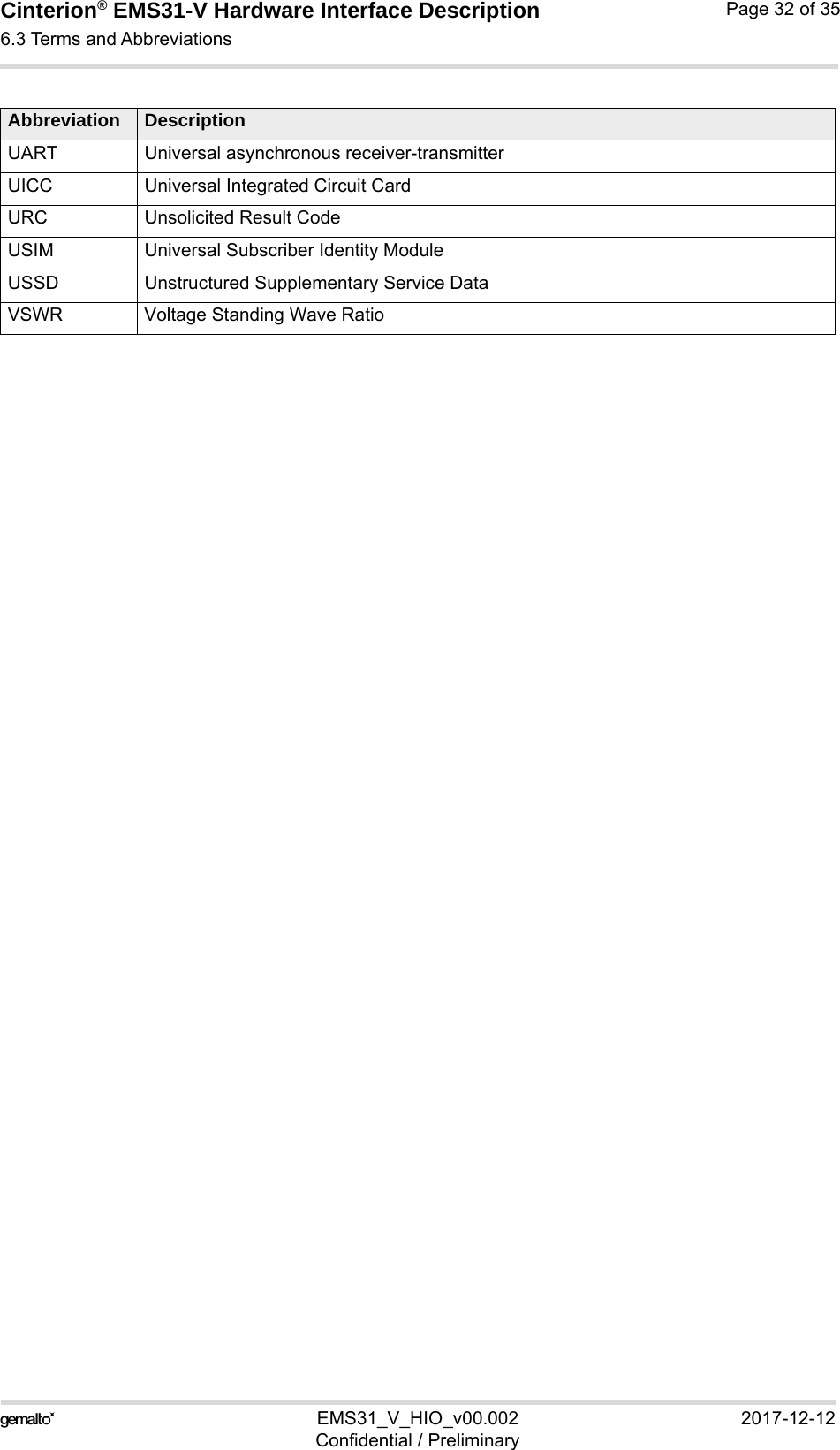
![Cinterion® EMS31-V Hardware Interface Description6.2 Related Documents33EMS31_V_HIO_v00.002 2017-12-12Confidential / PreliminaryPage 29 of 356.2 Related Documents[1] EMS31-V AT Command Set[2] EMS31-V Release Note[3] Application Note 48: SMT Module Integration[4] Universal Serial Bus Specification Revision 2.0, April 27, 20006.3 Terms and AbbreviationsAbbreviation DescriptionADC Analog-to-digital converterAGC Automatic Gain ControlANSI American National Standards InstituteARFCN Absolute Radio Frequency Channel NumberARP Antenna Reference PointASC0/ASC1 Asynchronous Controller. Abbreviations used for first and second serial interface of the moduleB Thermistor ConstantBER Bit Error RateBTS Base Transceiver StationCB or CBM Cell Broadcast MessageCE Conformité Européene (European Conformity)CHAP Challenge Handshake Authentication ProtocolCPU Central Processing UnitCS Coding SchemeCSD Circuit Switched DataCTS Clear to SendDAC Digital-to-Analog ConverterDAI Digital Audio InterfacedBm0 Digital level, 3.14dBm0 corresponds to full scale, see ITU G.711, A-lawDCE Data Communication Equipment (typically modems, e.g. Gemalto M2M module)DCS 1800 Digital Cellular System, also referred to as PCNDNI Does not implementedDRX Discontinuous ReceptionDSB Development Support BoxDSP Digital Signal ProcessorDSR Data Set ReadyDTE Data Terminal Equipment (typically computer, terminal, printer or, for example, GSM application)](https://usermanual.wiki/THALES-DIS-AlS-Deutschland/EMS31-V/User-Guide-3710344-Page-29.png)