THALES DIS AlS Deutschland GWM400 LTE/WCDMA Module User Manual hid
Gemalto M2M GmbH LTE/WCDMA Module hid
UserManual.wiki
>
THALES DIS AlS Deutschland
>
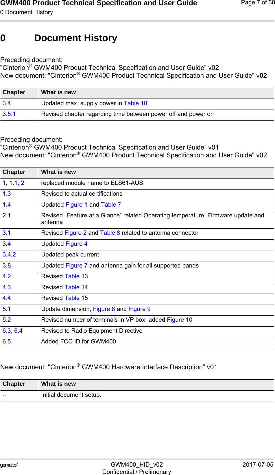
GWM400 User Manual
User Manual_REV 1
Navigation menu
Upload a User Manual
Namespaces
Wiki Guide
HTML
PDF
Info
Views
User Manual
Discussion / Help
Navigation
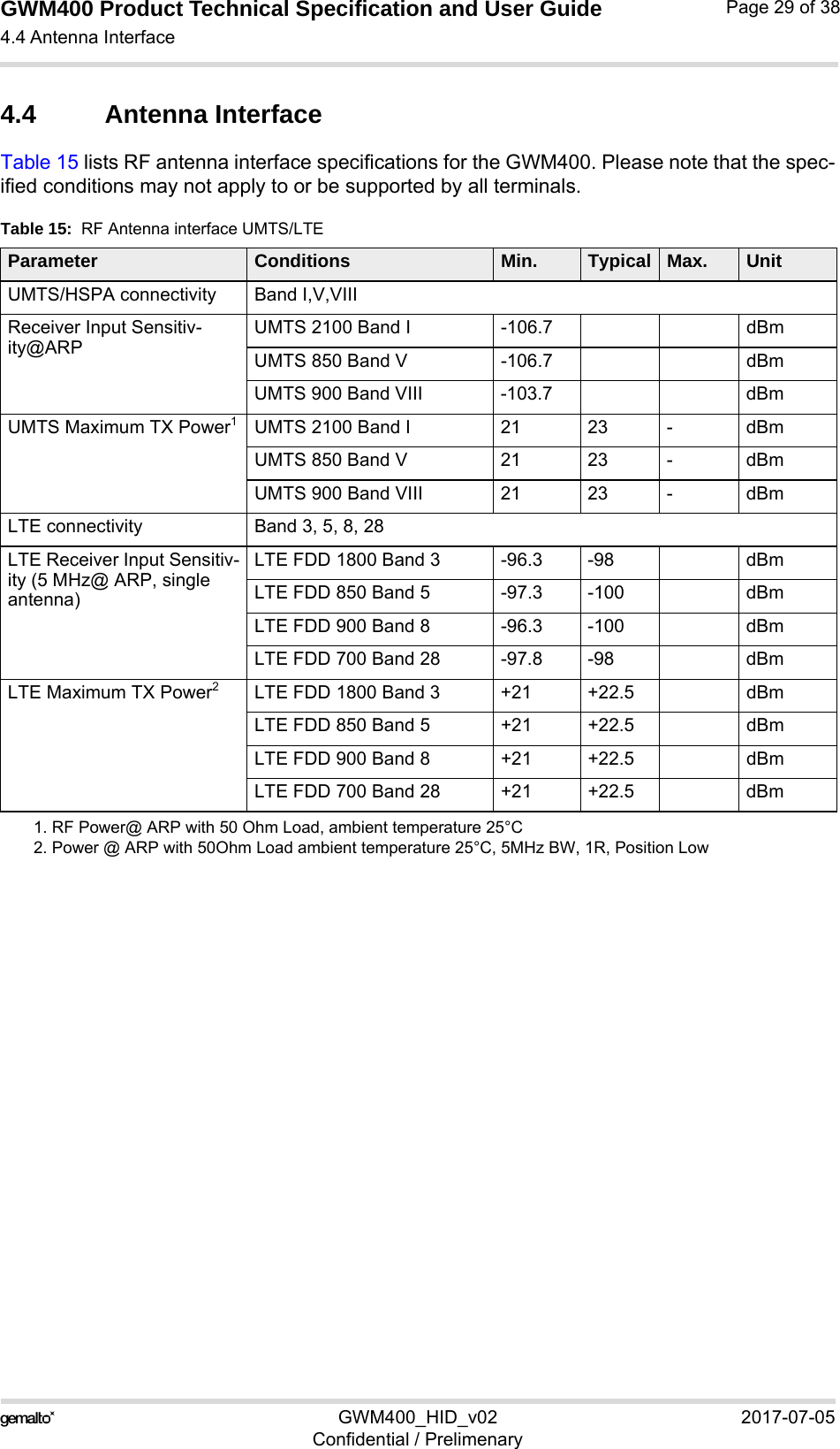
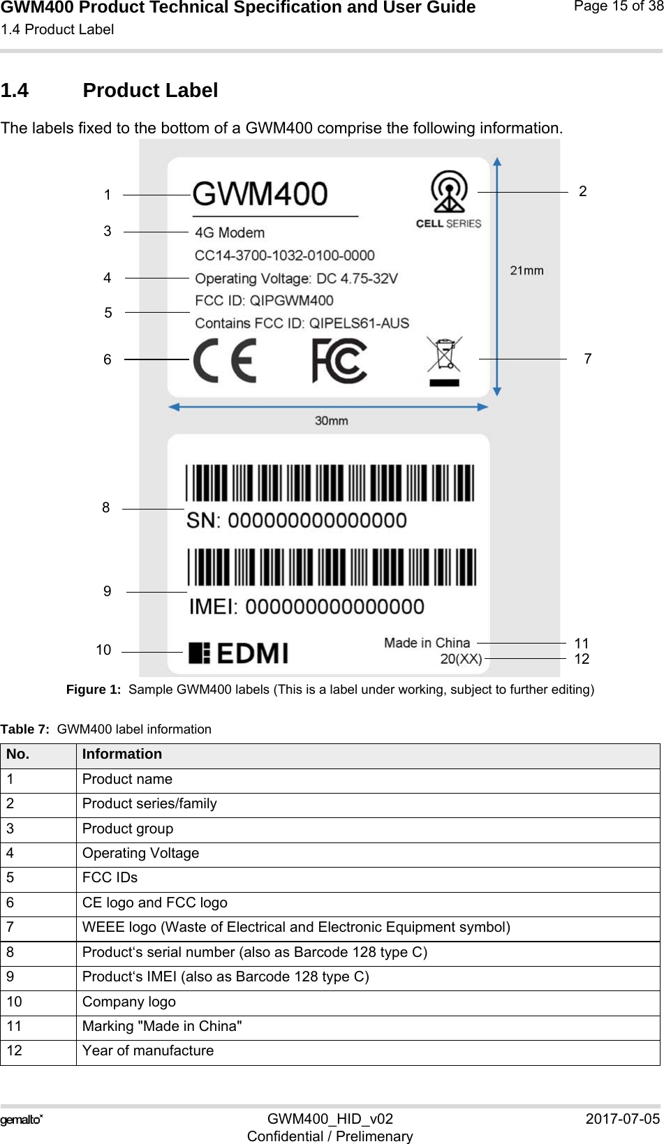
![GWM400 Product Technical Specification and User Guide1.1 Related Documents15GWM400_HID_v02 2017-07-05Confidential / PrelimenaryPage 9 of 381.1 Related Documents[1] AT Command Set for the Cinterion® ELS61-AUS module[2] Release Notes for the Cinterion® ELS61-AUS moduleTo visit the Gemalto M2M GmbH Website please use the following link:http://m2m.gemalto.com1.2 Terms and AbbreviationsTable 1: Terms and abbreviationsAbbreviation DescriptionACMA Australian Communications and Media AuthorityARP Antenna Reference PointATC AT CommandBTS Base Transceiver StationCB Cell BroadcastCE Communauté Européenne (originally)CODEC Coder-DecoderDAI Digital Audio InterfaceDCE Data Circuit terminating EquipmentDSR Data Set ReadyDTR Data Terminal ReadyEFR Enhanced Full RateEGSM Enhanced GSMEMC Electromagnetic CompatibilityESD Electrostatic DischargeETS European Telecommunication StandardFDMA Frequency Division Multiple AccessG.C.F. GSM Conformity ForumGSM Global Standard for Mobile CommunicationHW HardwareIC Integrated CircuitIF Intermediate Frequency IMEI International Mobile Equipment IdentifierI/O Input/ OutputIGT IgnitionISO International Standards Organization](https://usermanual.wiki/THALES-DIS-AlS-Deutschland/GWM400/User-Guide-3458978-Page-9.png)
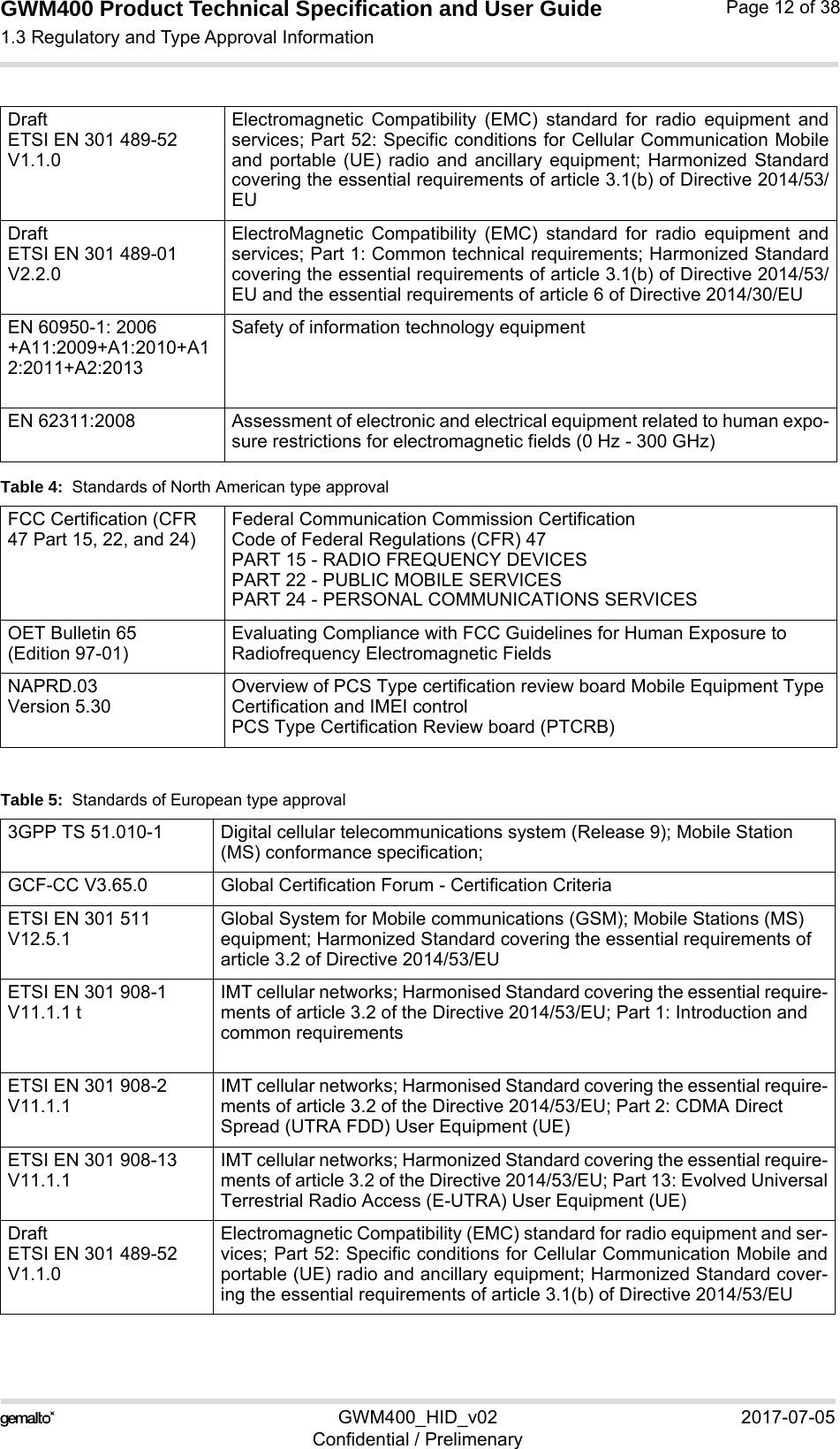
![GWM400 Product Technical Specification and User Guide1.3 Regulatory and Type Approval Information15GWM400_HID_v02 2017-07-05Confidential / PrelimenaryPage 13 of 38Draft ETSI EN 301 489-01 V2.2.0ElectroMagnetic Compatibility (EMC) standard for radio equipment and ser-vices; Part 1: Common technical requirements; Harmonized Standard cov-ering the essential requirements of article 3.1(b) of Directive 2014/53/EUand the essential requirements of article 6 of Directive 2014/30/EUEN 60950-1:2006+A11:2009+A1:2010+A12:2011Information technology equipment - Safety Part 1: General requirements (IEC 60950-1:2005, modified); Amendment A11: 2009; Amendment A1: 2010; Amendment A12: 2011EN 62311:2008 Assessment of electronic and electrical equipment related to human expo-sure restrictions for electromagnetic fields (0 Hz - 300 GHz) [Superseded: CENELEC EN 50392] Table 6: Requirements of qualityIEC 60068 Environmental testingDIN EN 60529 IP codesTable 5: Standards of European type approval](https://usermanual.wiki/THALES-DIS-AlS-Deutschland/GWM400/User-Guide-3458978-Page-13.png)
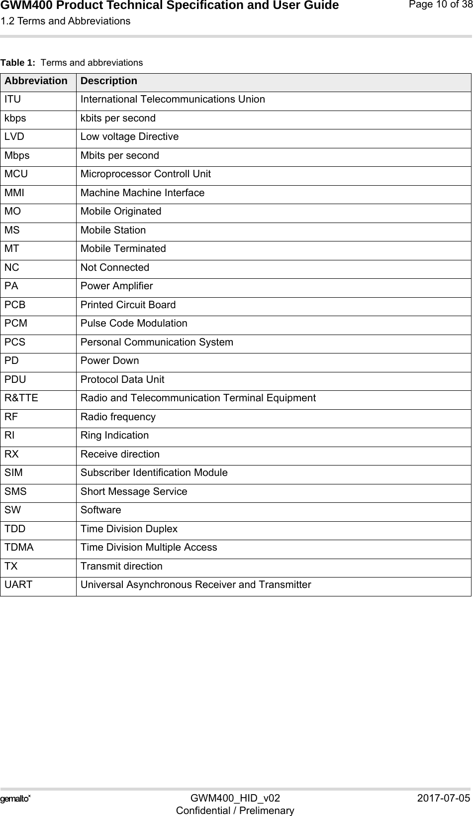
![GWM400 Product Technical Specification and User Guide3.3 Operating Modes25GWM400_HID_v02 2017-07-05Confidential / PrelimenaryPage 20 of 383.3 Operating ModesThe table below briefly summarizes the various operating modes referred to in the following chapters. Table 9: Overview of operating modesNormal operation UMTS / HSPA / LTESLEEPPower saving set automatically when no call is in prog-ress.UMTS / HSPA / LTEIDLEPower saving disabled, but no call in progress.UMTS DATA UMTS data transfer in progress. Power consumptiondepends on network settings (e.g. TPC Pattern) and datatransfer rate.HSPA DATA HSPA data transfer in progress. Power consumptiondepends on network settings (e.g. TPC Pattern) and datatransfer rate.LTE DATA LTE data transfer in progress. Power consumptiondepends on network settings (e.g. TPC Pattern) and datatransfer rate.Power Down Normal shutdown after sending the power down command. Only a voltage regu-lator is active for powering the RTC. Software is not active. Interfaces are notaccessible. Operating voltage remains applied.Airplane mode Airplane mode shuts down the radio part of the module, causes the module to log off from the network and disables all AT commands whose execution requires a radio connection.Airplane mode can be controlled by AT command (see [1]).](https://usermanual.wiki/THALES-DIS-AlS-Deutschland/GWM400/User-Guide-3458978-Page-20.png)
![GWM400 Product Technical Specification and User Guide3.5 Power Up/Power Down Scenarios25GWM400_HID_v02 2017-07-05Confidential / PrelimenaryPage 23 of 383.5 Power Up/Power Down ScenariosIn general, be sure not to turn on the GWM400 while it is beyond the safety limits of voltage stated in Section 4.1. GWM400 immediately switches off after having started and detected these inappropriate conditions. In extreme cases this can cause permanent damage to the GWM400.3.5.1 Turn GWM400 onGWM400 is automatically turned on and started into normal mode by plugging or by re-plug-ging an appropriate power supply unit at the power supply line BATT+.Every time before turn on the GWM400, it must be disconnected at least for 2 seconds from power supply to ensure turn on properly.3.5.2 Reset/Restart GWM400GWM400 can be reset/restarted by entering the command AT+CFUN=x,1. For details on AT+CFUN please see [1].3.5.3 Turn GWM400 offNormal shutdown:• To turn off the GWM400 use the AT^SMSO command, rather than disconnecting the mainsadapter. This switch off procedure lets the GWM400 log off from the network and allows the softwareto enter a secure state and save data before disconnecting the power supply. AfterAT^SMSO has been entered the GWM400 returns the following result codes: ^SMSO: MS OFFOK^SHUTDOWNThe "^SHUTDOWN" result code indicates that the GWM400 turns off in less than 1 second.After the shutdown procedure is complete the GWM400 enters the Power Down mode. TheRTC is still fed from the voltage regulator in the power supply ASIC.Only after power off and power on again, i.e., turning off and on the power supply line, can the terminal be switches on again. Apart from the normal shutdown. 3.5.4 Disconnecting Power SupplyBefore disconnecting the power supply from the BATT+ pin, make sure that the GWM400 is in a safe condition. The best way is to wait 1s after the "^SHUTDOWN" result code has been in-dicated.](https://usermanual.wiki/THALES-DIS-AlS-Deutschland/GWM400/User-Guide-3458978-Page-23.png)
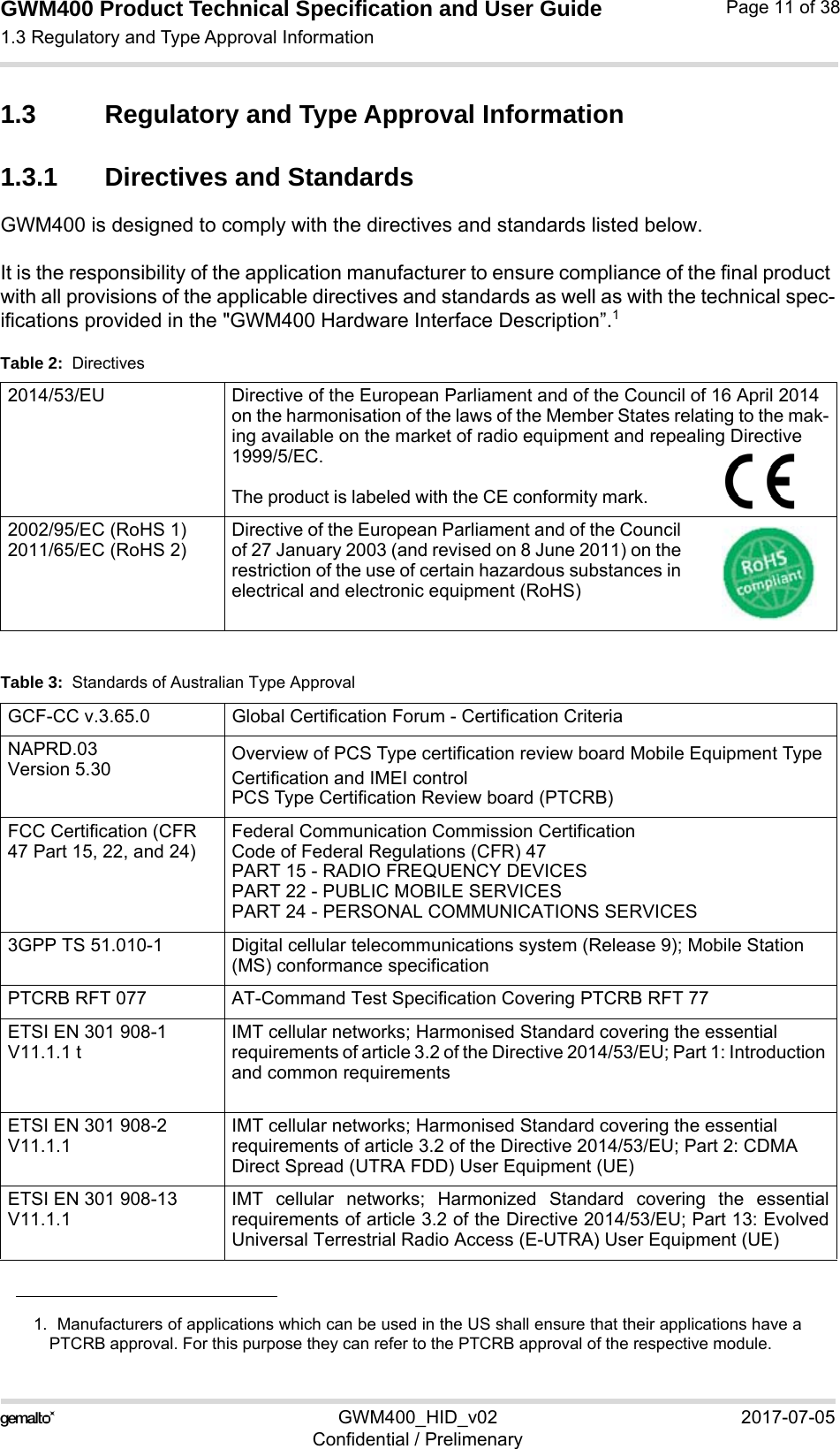
![GWM400 Product Technical Specification and User Guide3.6 SIM Interface25GWM400_HID_v02 2017-07-05Confidential / PrelimenaryPage 24 of 383.6 SIM Interface The SIM interface is intended for 1.8V and 3V SIM cards in accordance with 3GPP 31.102. The card holder is a five wire interface according to ETSI 102 221. The SIM card holder is protected by a rubber cover that has to be opened before a SIM can be inserted.Figure 5: SIM interfaceThe SIM - with the circuit side facing upwards - is inserted by gently pushing it into the SIM card holder until it snaps hold. It is now protected from accidental removal. The SIM can be removed from the card holder by using a flat object such as a screwdriver to carefully press the inserted SIM until it snaps out again.All signals of the SIM interface are protected from electrostatic discharge.Removing and inserting the SIM card during operation requires is not supported by GWM400. Note: No guarantee can be given, nor any liability accepted, if loss of data is encountered after removing the SIM card during operation. Also, no guarantee can be given for properly initializ-ing any SIM card that the user inserts after having removed a SIM card during operation. In this case, the application must restart the GWM400.3.7 Status LEDGWM400 has a green LED to indicate its operating status.Figure 6: Status LEDThe LED is enabled by default, but can be configured by AT command AT^SLED. For more information on the AT^SLED command please refer to [1]. SIM card readerStatus LED](https://usermanual.wiki/THALES-DIS-AlS-Deutschland/GWM400/User-Guide-3458978-Page-24.png)