THALES DIS AlS Deutschland GWM400 LTE/WCDMA Module User Manual hid
Gemalto M2M GmbH LTE/WCDMA Module hid
User Manual_REV 1
M2M.GEMALTO.COM
GWM400
Product Technical Specification and User Guide
Version: 03
DocId: GWM400_HID_v03

GENERAL NOTE
THE USE OF THE PRODUCT INCLUDING THE SOFTWARE AND DOCUMENTATION (THE "PROD-
UCT") IS SUBJECT TO THE RELEASE NOTE PROVIDED TOGETHER WITH PRODUCT. IN ANY
EVENT THE PROVISIONS OF THE RELEASE NOTE SHALL PREVAIL. THIS DOCUMENT CONTAINS
INFORMATION ON GEMALTO M2M PRODUCTS. THE SPECIFICATIONS IN THIS DOCUMENT ARE
SUBJECT TO CHANGE AT GEMALTO M2M'S DISCRETION. GEMALTO M2M GMBH GRANTS A NON-
EXCLUSIVE RIGHT TO USE THE PRODUCT. THE RECIPIENT SHALL NOT TRANSFER, COPY,
MODIFY, TRANSLATE, REVERSE ENGINEER, CREATE DERIVATIVE WORKS; DISASSEMBLE OR
DECOMPILE THE PRODUCT OR OTHERWISE USE THE PRODUCT EXCEPT AS SPECIFICALLY
AUTHORIZED. THE PRODUCT AND THIS DOCUMENT ARE PROVIDED ON AN "AS IS" BASIS ONLY
AND MAY CONTAIN DEFICIENCIES OR INADEQUACIES. TO THE MAXIMUM EXTENT PERMITTED
BY APPLICABLE LAW, GEMALTO M2M GMBH DISCLAIMS ALL WARRANTIES AND LIABILITIES.
THE RECIPIENT UNDERTAKES FOR AN UNLIMITED PERIOD OF TIME TO OBSERVE SECRECY
REGARDING ANY INFORMATION AND DATA PROVIDED TO HIM IN THE CONTEXT OF THE DELIV-
ERY OF THE PRODUCT. THIS GENERAL NOTE SHALL BE GOVERNED AND CONSTRUED
ACCORDING TO GERMAN LAW.
Copyright
Transmittal, reproduction, dissemination and/or editing of this document as well as utilization of its con-
tents and communication thereof to others without express authorization are prohibited. Offenders will be
held liable for payment of damages. All rights created by patent grant or registration of a utility model or
design patent are reserved.
Copyright © 2017, Gemalto M2M GmbH, a Gemalto Company
Trademark Notice
Gemalto, the Gemalto logo, are trademarks and service marks of Gemalto and are registered in certain
countries. Microsoft and Windows are either registered trademarks or trademarks of Microsoft Corpora-
tion in the United States and/or other countries. All other registered trademarks or trademarks mentioned
in this document are property of their respective owners.
GWM400_HID_v03 2017-07-05
Confidential / Prelimenary
GWM400 Product Technical Specification and User Guide
2
Page 2 of 38
Document Name: GWM400 Product Technical Specification and User Guide
Version: 03
Date: 2017-07-05
DocId: GWM400_HID_v03
Status Confidential / Prelimenary

GWM400 Product Technical Specification and User Guide
Contents
125
GWM400_HID_v02 2017-07-05
Confidential / Prelimenary
Page 3 of 38
Contents
0 Document History ...................................................................................................... 7
1 Introduction ................................................................................................................. 8
1.1 Related Documents ........................................................................................... 9
1.2 Terms and Abbreviations ................................................................................... 9
1.3 Regulatory and Type Approval Information ..................................................... 11
1.3.1 Directives and Standards.................................................................... 11
1.3.2 Safety Precautions.............................................................................. 14
1.4 Product Label................................................................................................... 15
2 Product Concept ....................................................................................................... 16
2.1 Key Features at a Glance ................................................................................ 16
3 Interface Description ................................................................................................ 18
3.1 Overview .......................................................................................................... 18
3.2 Block Diagram.................................................................................................. 19
3.3 Operating Modes ............................................................................................. 20
3.4 Molex Microfit Connector ................................................................................. 21
3.4.1 RS-232 Interface................................................................................. 22
3.4.2 Power Supply...................................................................................... 22
3.5 Power Up/Power Down Scenarios................................................................... 23
3.5.1 Turn GWM400 on ............................................................................... 23
3.5.2 Reset/Restart GWM400...................................................................... 23
3.5.3 Turn GWM400 off ............................................................................... 23
3.5.4 Disconnecting Power Supply .............................................................. 23
3.6 SIM Interface.................................................................................................... 24
3.7 Status LED....................................................................................................... 24
3.8 RF Antenna Interface....................................................................................... 25
4 Electrical and Environmental Characteristics........................................................ 26
4.1 Absolute Maximum Ratings ............................................................................. 26
4.2 Power Supply Ratings...................................................................................... 27
4.3 Operating Temperatures.................................................................................. 28
4.4 Antenna Interface............................................................................................. 29
4.5 Storage Conditions .......................................................................................... 30
5 Mechanics, Mounting and Packaging ..................................................................... 31
5.1 Mechanical Dimensions ................................................................................... 31
5.2 Packaging ........................................................................................................ 33

GWM400 Product Technical Specification and User Guide
Contents
125
GWM400_HID_v02 2017-07-05
Confidential / Prelimenary
Page 4 of 38
6 Full Type Approval.................................................................................................... 34
6.1 Gemalto M2M Reference Setup ...................................................................... 34
6.2 Restrictions ...................................................................................................... 35
6.3 CE Conformity.................................................................................................. 35
6.4 EMC ................................................................................................................. 35
6.5 Compliance with FCC Rules and Regulations ................................................. 36
7 List of Parts and Accessories.................................................................................. 37

GWM400 Product Technical Specification and User Guide
Tab le s
5
GWM400_HID_v02 2017-07-05
Confidential / Prelimenary
Page 5 of 38
Tables
Table 1: Terms and abbreviations................................................................................... 9
Table 2: Directives ........................................................................................................ 11
Table 3: Standards of Australian Type Approval........................................................... 11
Table 4: Standards of North American type approval ................................................... 12
Table 5: Standards of European type approval............................................................. 12
Table 6: Requirements of quality .................................................................................. 13
Table 7: GWM400 label information.............................................................................. 15
Table 8: GWM400‘ interfaces........................................................................................ 18
Table 9: Overview of operating modes ......................................................................... 20
Table 10: 8-pin Molex Microfit connector ........................................................................ 21
Table 11: Absolute maximum ratings.............................................................................. 26
Table 12: Operating supply voltage for GWM400........................................................... 26
Table 13: Power supply specification.............................................................................. 27
Table 14: Temperature characteristics............................................................................ 28
Table 15: RF Antenna interface UMTS/LTE ................................................................... 29
Table 16: Storage conditions .......................................................................................... 30
Table 17: List of parts and accessories........................................................................... 37

GWM400 Product Technical Specification and User Guide
Figures
6
GWM400_HID_v02 2017-07-05
Confidential / Prelimenary
Page 6 of 38
Figures
Figure 1: Sample GWM400 labels
(This is a label under working, subject to further editing)................................ 15
Figure 2: GWM400 interfaces ........................................................................................ 18
Figure 3: Block diagram ................................................................................................. 19
Figure 4: Pin assignment Molex Microfit ........................................................................ 21
Figure 5: SIM interface................................................................................................... 24
Figure 6: Status LED...................................................................................................... 24
Figure 7: Antenna connector.......................................................................................... 25
Figure 8: GWM400 3D overview .................................................................................... 31
Figure 9: GWM400 exploded view ................................................................................. 32
Figure 10: Packaging of GWM400 ................................................................................... 33
Figure 11: Reference equipment for approval.................................................................. 34

GWM400 Product Technical Specification and User Guide
0 Document History
7
GWM400_HID_v02 2017-07-05
Confidential / Prelimenary
Page 7 of 38
0 Document History
Preceding document:
"Cinterion® GWM400 Product Technical Specification and User Guide” v02
New document: "Cinterion® GWM400 Product Technical Specification and User Guide" v02
Preceding document:
"Cinterion® GWM400 Product Technical Specification and User Guide” v01
New document: "Cinterion® GWM400 Product Technical Specification and User Guide" v02
New document: "Cinterion® GWM400 Hardware Interface Description” v01
Chapter What is new
3.4 Updated max. supply power in Table 10
3.5.1 Revised chapter regarding time between power off and power on
Chapter What is new
1, 1.1, 2replaced module name to ELS61-AUS
1.3 Revised to actual certifications
1.4 Updated Figure 1 and Table 7
2.1 Revised “Feature at a Glance” related Operating temperature, Firmware update and
antenna
3.1 Revised Figure 2 and Table 8 related to antenna connector
3.4 Updated Figure 4
3.4.2 Updated peak current
3.8 Updated Figure 7 and antenna gain for all supported bands
4.2 Revised Table 13
4.3 Revised Table 14
4.4 Revised Table 15
5.1 Update dimension, Figure 8 and Figure 9
5.2 Revised number of terminals in VP box, added Figure 10
6.3, 6.4 Revised to Radio Equipment Directive
6.5 Added FCC ID for GWM400
Chapter What is new
-- Initial document setup.

GWM400 Product Technical Specification and User Guide
1 Introduction
15
GWM400_HID_v02 2017-07-05
Confidential / Prelimenary
Page 8 of 38
1 Introduction
This document1 describes the hardware of the GWM400. The GWM400 contains a Cinterion®
ELS61-AUS module, and has an RS-232 compatible interface with an 8-pin Molex Microfit con-
nector, including power supply, and an RF antenna connector.
The scope of this document includes interface specifications, electrical as well as mechanical
characteristics of the GWM400. It specifies standards pertaining to wireless applications and
outlines requirements that must be adhered to for successful product design.
The GWM400 is a compact WCDMA/LTE modem to transfer data to/from other devices, such
as smart meter, to the mobile network. It is easy to use the GWM400 as a WCDMA/LTE termi-
nal. The GWM400 has an industrial standard serial interface that can be used to transfer data
to/from the connected device. The connected device can also send AT commands via this se-
rial interface, to control GWM400. The GWM400 supports triple band WCDMA and quad band
LTE. It has an integrated SIM card reader supporting 1.8V and 3V SIM cards.
GWM400 is not intended for use in vehicular environments.
1. The document is effective only if listed in the appropriate Release Notes as part of the technical docu-
mentation delivered with your Gemalto M2M product.

GWM400 Product Technical Specification and User Guide
1.1 Related Documents
15
GWM400_HID_v02 2017-07-05
Confidential / Prelimenary
Page 9 of 38
1.1 Related Documents
[1] AT Command Set for the Cinterion® ELS61-AUS module
[2] Release Notes for the Cinterion® ELS61-AUS module
To visit the Gemalto M2M GmbH Website please use the following link:
http://m2m.gemalto.com
1.2 Terms and Abbreviations
Table 1: Terms and abbreviations
Abbreviation Description
ACMA Australian Communications and Media Authority
ARP Antenna Reference Point
ATC AT Command
BTS Base Transceiver Station
CB Cell Broadcast
CE Communauté Européenne (originally)
CODEC Coder-Decoder
DAI Digital Audio Interface
DCE Data Circuit terminating Equipment
DSR Data Set Ready
DTR Data Terminal Ready
EFR Enhanced Full Rate
EGSM Enhanced GSM
EMC Electromagnetic Compatibility
ESD Electrostatic Discharge
ETS European Telecommunication Standard
FDMA Frequency Division Multiple Access
G.C.F. GSM Conformity Forum
GSM Global Standard for Mobile Communication
HW Hardware
IC Integrated Circuit
IF Intermediate Frequency
IMEI International Mobile Equipment Identifier
I/O Input/ Output
IGT Ignition
ISO International Standards Organization

GWM400 Product Technical Specification and User Guide
1.2 Terms and Abbreviations
15
GWM400_HID_v02 2017-07-05
Confidential / Prelimenary
Page 10 of 38
ITU International Telecommunications Union
kbps kbits per second
LVD Low voltage Directive
Mbps Mbits per second
MCU Microprocessor Controll Unit
MMI Machine Machine Interface
MO Mobile Originated
MS Mobile Station
MT Mobile Terminated
NC Not Connected
PA Power Amplifier
PCB Printed Circuit Board
PCM Pulse Code Modulation
PCS Personal Communication System
PD Power Down
PDU Protocol Data Unit
R&TTE Radio and Telecommunication Terminal Equipment
RF Radio frequency
RI Ring Indication
RX Receive direction
SIM Subscriber Identification Module
SMS Short Message Service
SW Software
TDD Time Division Duplex
TDMA Time Division Multiple Access
TX Transmit direction
UART Universal Asynchronous Receiver and Transmitter
Table 1: Terms and abbreviations
Abbreviation Description
GWM400 Product Technical Specification and User Guide
1.3 Regulatory and Type Approval Information
15
GWM400_HID_v02 2017-07-05
Confidential / Prelimenary
Page 11 of 38
1.3 Regulatory and Type Approval Information
1.3.1 Directives and Standards
GWM400 is designed to comply with the directives and standards listed below.
It is the responsibility of the application manufacturer to ensure compliance of the final product
with all provisions of the applicable directives and standards as well as with the technical spec-
ifications provided in the "GWM400 Hardware Interface Description”.1
Table 3: Standards of Australian Type Approval
1. Manufacturers of applications which can be used in the US shall ensure that their applications have a
PTCRB approval. For this purpose they can refer to the PTCRB approval of the respective module.
Table 2: Directives
2014/53/EU Directive of the European Parliament and of the Council of 16 April 2014
on the harmonisation of the laws of the Member States relating to the mak-
ing available on the market of radio equipment and repealing Directive
1999/5/EC.
The product is labeled with the CE conformity mark.
2002/95/EC (RoHS 1)
2011/65/EC (RoHS 2)
Directive of the European Parliament and of the Council
of 27 January 2003 (and revised on 8 June 2011) on the
restriction of the use of certain hazardous substances in
electrical and electronic equipment (RoHS)
GCF-CC v.3.65.0 Global Certification Forum - Certification Criteria
NAPRD.03
Version 5.30 Overview of PCS Type certification review board Mobile Equipment Type
Certification and IMEI control
PCS Type Certification Review board (PTCRB)
FCC Certification (CFR
47 Part 15, 22, and 24) Federal Communication Commission Certification
Code of Federal Regulations (CFR) 47
PART 15 - RADIO FREQUENCY DEVICES
PART 22 - PUBLIC MOBILE SERVICES
PART 24 - PERSONAL COMMUNICATIONS SERVICES
3GPP TS 51.010-1 Digital cellular telecommunications system (Release 9); Mobile Station
(MS) conformance specification
PTCRB RFT 077 AT-Command Test Specification Covering PTCRB RFT 77
ETSI EN 301 908-1
V11.1.1 t
IMT cellular networks; Harmonised Standard covering the essential
requirements of article 3.2 of the Directive 2014/53/EU; Part 1: Introduction
and common requirements
ETSI EN 301 908-2
V11.1.1
IMT cellular networks; Harmonised Standard covering the essential
requirements of article 3.2 of the Directive 2014/53/EU; Part 2: CDMA
Direct Spread (UTRA FDD) User Equipment (UE)
ETSI EN 301 908-13
V11.1.1
IMT cellular networks; Harmonized Standard covering the essential
requirements of article 3.2 of the Directive 2014/53/EU; Part 13: Evolved
Universal Terrestrial Radio Access (E-UTRA) User Equipment (UE)

GWM400 Product Technical Specification and User Guide
1.3 Regulatory and Type Approval Information
15
GWM400_HID_v02 2017-07-05
Confidential / Prelimenary
Page 12 of 38
Draft
ETSI EN 301 489-52
V1.1.0
Electromagnetic Compatibility (EMC) standard for radio equipment and
services; Part 52: Specific conditions for Cellular Communication Mobile
and portable (UE) radio and ancillary equipment; Harmonized Standard
covering the essential requirements of article 3.1(b) of Directive 2014/53/
EU
Draft
ETSI EN 301 489-01
V2.2.0
ElectroMagnetic Compatibility (EMC) standard for radio equipment and
services; Part 1: Common technical requirements; Harmonized Standard
covering the essential requirements of article 3.1(b) of Directive 2014/53/
EU and the essential requirements of article 6 of Directive 2014/30/EU
EN 60950-1: 2006
+A11:2009+A1:2010+A1
2:2011+A2:2013
Safety of information technology equipment
EN 62311:2008 Assessment of electronic and electrical equipment related to human expo-
sure restrictions for electromagnetic fields (0 Hz - 300 GHz)
Table 4: Standards of North American type approval
FCC Certification (CFR
47 Part 15, 22, and 24) Federal Communication Commission Certification
Code of Federal Regulations (CFR) 47
PART 15 - RADIO FREQUENCY DEVICES
PART 22 - PUBLIC MOBILE SERVICES
PART 24 - PERSONAL COMMUNICATIONS SERVICES
OET Bulletin 65
(Edition 97-01)
Evaluating Compliance with FCC Guidelines for Human Exposure to
Radiofrequency Electromagnetic Fields
NAPRD.03
Version 5.30
Overview of PCS Type certification review board Mobile Equipment Type
Certification and IMEI control
PCS Type Certification Review board (PTCRB)
Table 5: Standards of European type approval
3GPP TS 51.010-1 Digital cellular telecommunications system (Release 9); Mobile Station
(MS) conformance specification;
GCF-CC V3.65.0 Global Certification Forum - Certification Criteria
ETSI EN 301 511
V12.5.1
Global System for Mobile communications (GSM); Mobile Stations (MS)
equipment; Harmonized Standard covering the essential requirements of
article 3.2 of Directive 2014/53/EU
ETSI EN 301 908-1
V11.1.1 t
IMT cellular networks; Harmonised Standard covering the essential require-
ments of article 3.2 of the Directive 2014/53/EU; Part 1: Introduction and
common requirements
ETSI EN 301 908-2
V11.1.1
IMT cellular networks; Harmonised Standard covering the essential require-
ments of article 3.2 of the Directive 2014/53/EU; Part 2: CDMA Direct
Spread (UTRA FDD) User Equipment (UE)
ETSI EN 301 908-13
V11.1.1
IMT cellular networks; Harmonized Standard covering the essential require-
ments of article 3.2 of the Directive 2014/53/EU; Part 13: Evolved Universal
Terrestrial Radio Access (E-UTRA) User Equipment (UE)
Draft
ETSI EN 301 489-52
V1.1.0
Electromagnetic Compatibility (EMC) standard for radio equipment and ser-
vices; Part 52: Specific conditions for Cellular Communication Mobile and
portable (UE) radio and ancillary equipment; Harmonized Standard cover-
ing the essential requirements of article 3.1(b) of Directive 2014/53/EU

GWM400 Product Technical Specification and User Guide
1.3 Regulatory and Type Approval Information
15
GWM400_HID_v02 2017-07-05
Confidential / Prelimenary
Page 13 of 38
Draft
ETSI EN 301 489-01
V2.2.0
ElectroMagnetic Compatibility (EMC) standard for radio equipment and ser-
vices; Part 1: Common technical requirements; Harmonized Standard cov-
ering the essential requirements of article 3.1(b) of Directive 2014/53/EU
and the essential requirements of article 6 of Directive 2014/30/EU
EN 60950-1:2006
+A11:2009
+A1:2010
+A12:2011
Information technology equipment - Safety Part 1: General requirements
(IEC 60950-1:2005, modified); Amendment A11: 2009; Amendment A1:
2010; Amendment A12: 2011
EN 62311:2008 Assessment of electronic and electrical equipment related to human expo-
sure restrictions for electromagnetic fields (0 Hz - 300 GHz) [Superseded:
CENELEC EN 50392]
Table 6: Requirements of quality
IEC 60068 Environmental testing
DIN EN 60529 IP codes
Table 5: Standards of European type approval
GWM400 Product Technical Specification and User Guide
1.3 Regulatory and Type Approval Information
15
GWM400_HID_v02 2017-07-05
Confidential / Prelimenary
Page 14 of 38
1.3.2 Safety Precautions
The following safety precautions must be observed during all phases of the operation, usage,
service or repair of any cellular terminal or mobile incorporating GWM400. Manufacturers of
the cellular terminal are advised to convey the following safety information to users and oper-
ating personnel and to incorporate these guidelines into all manuals supplied with the product.
Failure to comply with these precautions violates safety standards of design, manufacture and
intended use of the product. Gemalto M2M assumes no liability for customer’s failure to comply
with these precautions.
When in a hospital or other health care facility, observe the restrictions on the use of
mobiles. Switch the cellular terminal or mobile off, if instructed to do so by the guide-
lines posted in sensitive areas. Medical equipment may be sensitive to RF energy.
The operation of cardiac pacemakers, other implanted medical equipment and hear-
ing aids can be affected by interference from cellular terminals or mobiles placed close
to the device. If in doubt about potential danger, contact the physician or the manufac-
turer of the device to verify that the equipment is properly shielded. Pacemaker
patients are advised to keep their hand-held mobile away from the pacemaker, while
it is on.
Switch off the cellular terminal or mobile before boarding an aircraft. Make sure it can-
not be switched on inadvertently. The operation of wireless appliances in an aircraft is
forbidden to prevent interference with communications systems. Failure to observe
these instructions may lead to the suspension or denial of cellular services to the
offender, legal action, or both.
Do not operate the cellular terminal or mobile in the presence of flammable gases or
fumes. Switch off the cellular terminal when you are near petrol stations, fuel depots,
chemical plants or where blasting operations are in progress. Operation of any elec-
trical equipment in potentially explosive atmospheres can constitute a safety hazard.
Your cellular terminal or mobile receives and transmits radio frequency energy while
switched on. Remember that interference can occur if it is used close to TV sets,
radios, computers or inadequately shielded equipment. Follow any special regulations
and always switch off the cellular terminal or mobile wherever forbidden, or when you
suspect that it may cause interference or danger.
Road safety comes first! Do not use a hand-held cellular terminal or mobile when driv-
ing a vehicle, unless it is securely mounted in a holder for speakerphone operation.
Before making a call with a hand-held terminal or mobile, park the vehicle.
Speakerphones must be installed by qualified personnel. Faulty installation or opera-
tion can constitute a safety hazard.
IMPORTANT!
Cellular terminals or mobiles operate using radio signals and cellular networks.
Because of this, connection cannot be guaranteed at all times under all conditions.
Therefore, you should never rely solely upon any wireless device for essential com-
munications, for example emergency calls.
Remember, in order to make or receive calls, the cellular terminal or mobile must be
switched on and in a service area with adequate cellular signal strength.
Some networks do not allow for emergency calls if certain network services or phone
features are in use (e.g. lock functions, fixed dialing etc.). You may need to deactivate
those features before you can make an emergency call.
Some networks require that a valid SIM card be properly inserted in the cellular termi-
nal or mobile.
GWM400 Product Technical Specification and User Guide
1.4 Product Label
15
GWM400_HID_v02 2017-07-05
Confidential / Prelimenary
Page 15 of 38
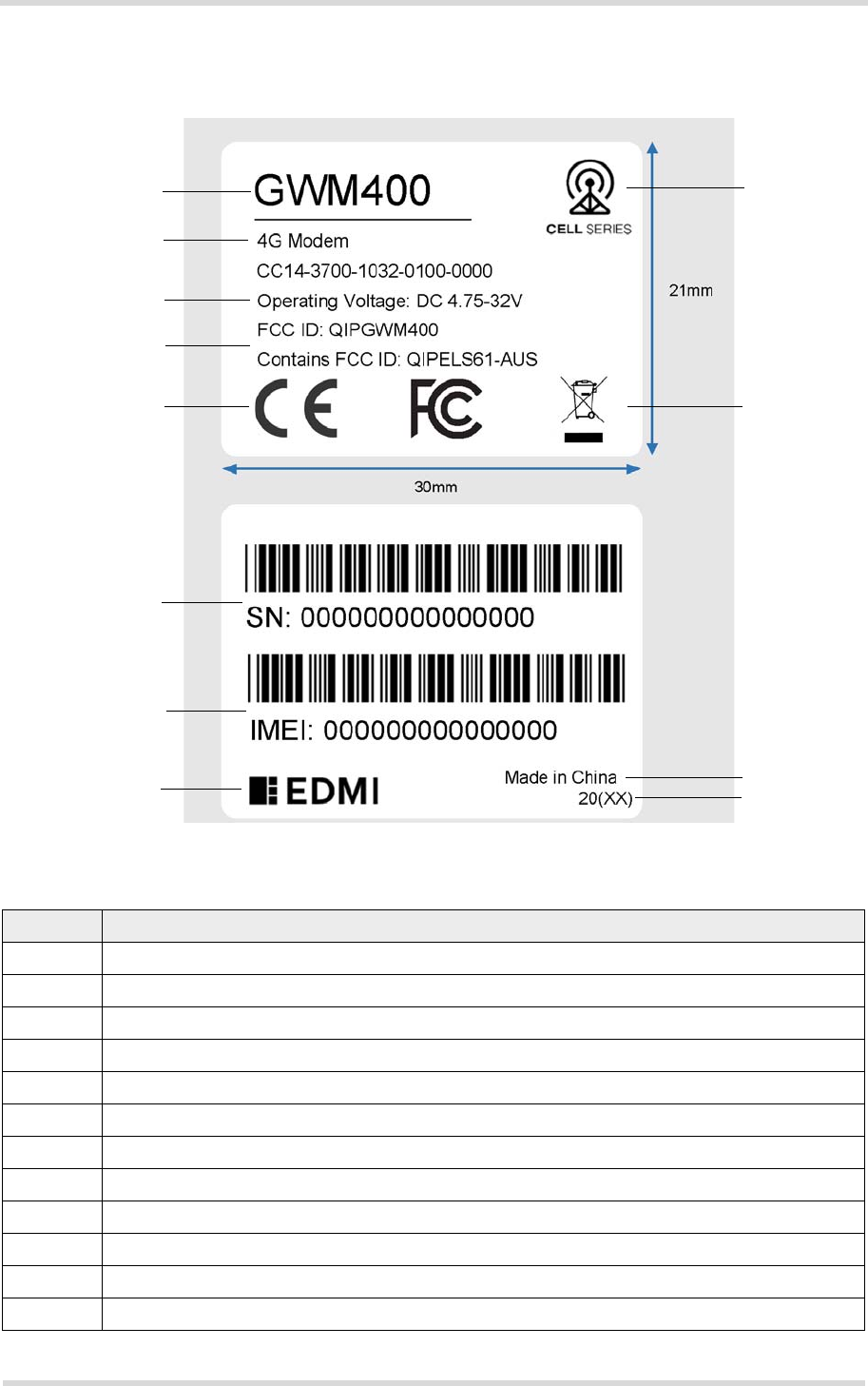
1.4 Product Label
The labels fixed to the bottom of a GWM400 comprise the following information.
Figure 1: Sample GWM400 labels (This is a label under working, subject to further editing)
Table 7: GWM400 label information
No. Information
1 Product name
2 Product series/family
3 Product group
4 Operating Voltage
5 FCC IDs
6 CE logo and FCC logo
7 WEEE logo (Waste of Electrical and Electronic Equipment symbol)
8 Product‘s serial number (also as Barcode 128 type C)
9 Product‘s IMEI (also as Barcode 128 type C)
10 Company logo
11 Marking "Made in China"
12 Year of manufacture
1
3
4
6
2
7
8
9
10 11
12
5

GWM400 Product Technical Specification and User Guide
2 Product Concept
17
GWM400_HID_v02 2017-07-05
Confidential / Prelimenary
Page 16 of 38
2 Product Concept
2.1 Key Features at a Glance
Feature Implementation
General
Incorporates Cinterion®
Java module
The Java module handles all signal and data processing within the
GWM400. Internal software runs the application interface and the complete
WCDMA/LTE protocol stack.
Frequency bands GWM400 (with ELS61-AUS module):
UMTS/HSPA+: Triple band, 850 (BdV) / 900 (BdVIII) / 2100 MHz (BdI)
LTE: Quad band, 700 (Bd28) / 900 (Bd8) / 850 (Bd5) / 1800MHz (Bd3)
Output power (according
to Release 99)
Class 3 (+24dBm +1/-3dB) for UMTS 2100,WCDMA FDD BdI
Class 3 (+24dBm +1/-3dB) for UMTS 900, WCDMA FDD BdV
Class 3 (+24dBm +1/-3dB) for UMTS 850, WCDMA FDD BdVIII
Output power (according
to Release 8)
Class 3 (+23dBm ±2dB) for LTE 700, LTE FDD Bd28
Class 3 (+23dBm ±2dB) for LTE 900, LTE FDD Bd8
Class 3 (+23dBm ±2dB) for LTE 850, LTE FDD Bd5
Class 3 (+23dBm ±2dB) for LTE 1800, LTE FDD Bd3
Power supply 4.75V to 32V
Operating temperature
(ambient temperature)
Normal operation: -30°C to +75°C
Physical Dimensions: 76.7mm x 51.5mm x 23.5 m
Weight: approx. 60g
LTE features
3GPP Release 9 UE CAT 1 supported
DL 10.2Mbps, UL 5.2Mbps
HSPA features
3GPP Release 8 DL 7.2Mbps, UL 5.7Mbps
HSDPA Cat.8 / HSUPA Cat.6 data rates
Compressed mode (CM) supported according to 3GPP TS25.212
UMTS features
3GPP Release 4 PS data rate – 384 kbps DL / 384 kbps UL
CS data rate – 64 kbps DL / 64 kbps UL
SMS Point-to-point MT and MO
Cell broadcast
Text and PDU mode
Storage: SIM card plus SMS locations in mobile equipment
Software
AT commands Hayes 3GPP TS 27.007, TS 27.005, Gemalto M2M
AT commands for RIL compatibility

GWM400 Product Technical Specification and User Guide
2.1 Key Features at a Glance
17
GWM400_HID_v02 2017-07-05
Confidential / Prelimenary
Page 17 of 38
Java™ Open Platform Java™ Open Platform with
• Java™ profile IMP-NG & CLDC 1.1 HI
• Secure data transmission via HTTPS/SSL
• Multi-threading programming and multi-application execution
Major benefits: seamless integration into Java applications, ease of pro-
gramming, no need for application microcontroller, extremely cost-efficient
hardware and software design – ideal platform for industrial applications.
The memory space available for Java programs is 30MB in the flash file
system and 18MB RAM. Application code and data share the space in the
flash file system and in RAM.
Microsoft™ compatibility RIL for Pocket PC and Smartphone
SIM Application Toolkit SAT letter classes b, c, e; with BIP
Firmware update Generic update from host application over ASC0.
Interfaces
RS232 RS-232 interface as part of 8-pin Molex Microfit for AT commands and data:
• Supports RTS/CTS hardware handshake
• Supports software XON/XOFF flow control
• Multiplex ability according to GSM 07.10 Multiplexer protocol
• Baud rates from 1200bps to 921,600bps, default: 9600bps
• Autobauding supported
Power supply Power supply (BATT+) as part of 8-pin Molex Microfit
SIM card reader Supported SIM/USIM cards: 3V, 1.8V
Antenna Antenna connected via SMA connector (jack)
Power on/off, Reset
Power on Power supply line at power connector
Power off Normal switch-off by AT^SMSO
Automatic switch-off in case of critical temperature or voltage conditions
Reset Orderly shutdown and reset by AT command
Special features
Status indication LED to indicate operating status.
Real time clock Timer functions via AT commands
Feature Implementation
GWM400 Product Technical Specification and User Guide
3 Interface Description
25
GWM400_HID_v02 2017-07-05
Confidential / Prelimenary
Page 18 of 38
3 Interface Description
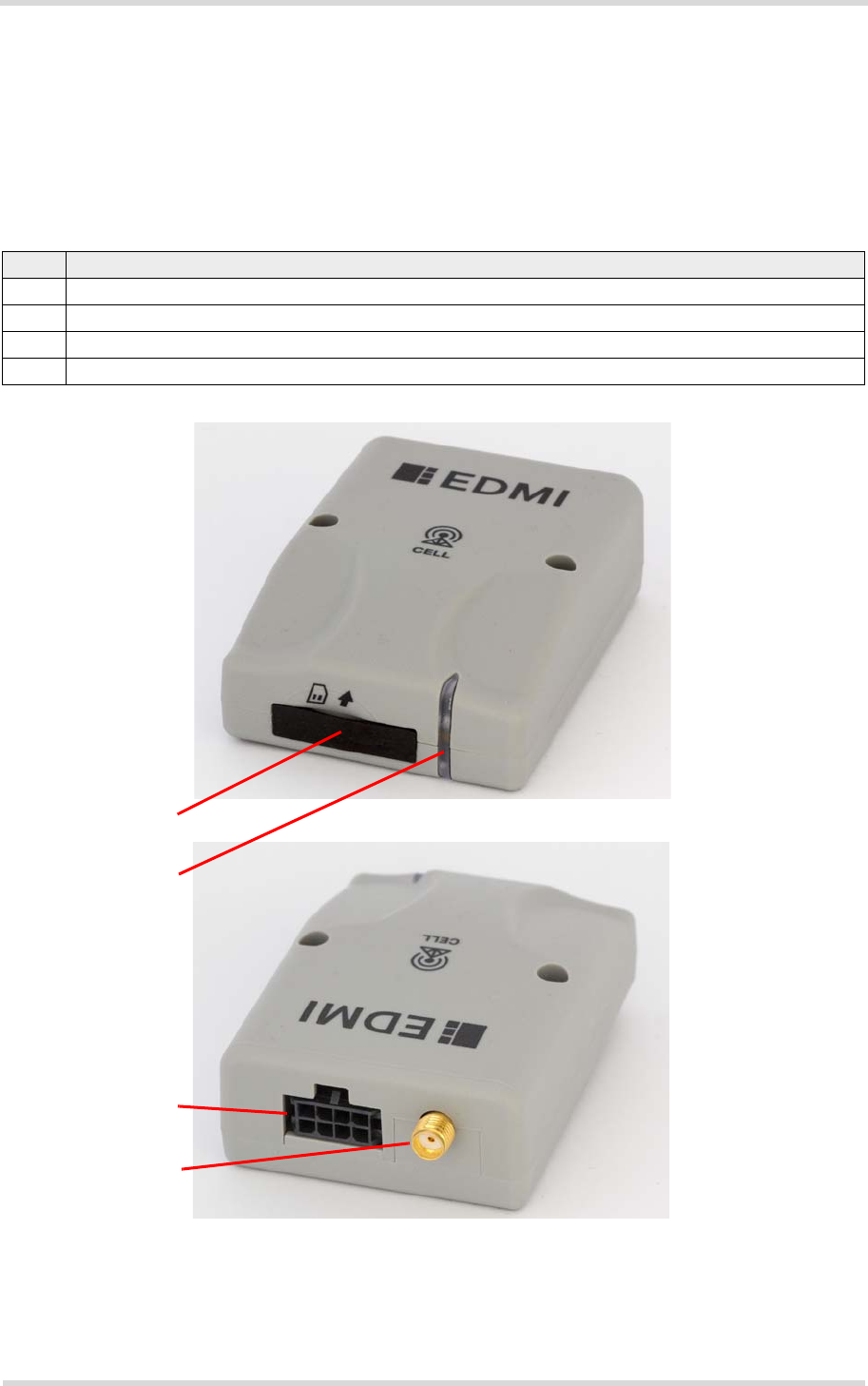
3.1 Overview
GWM400 provide the following interfaces for power supply, operating status indication, anten-
na, SIM card and data transfer:
Figure 2: GWM400 interfaces
Table 8: GWM400‘ interfaces
No. Description
1 SIM card reader (FF2, rubber cover, no hot plug)
2 LED (green) showing operating status LED
3 8-pin Molex Microfit connector (female) for data transfer (RS-232 interface) and power supply
4 SMA connector (jack) for RF antenna
1
3
2
4
Front view
Back view
GWM400 Product Technical Specification and User Guide
3.2 Block Diagram
25
GWM400_HID_v02 2017-07-05
Confidential / Prelimenary
Page 19 of 38
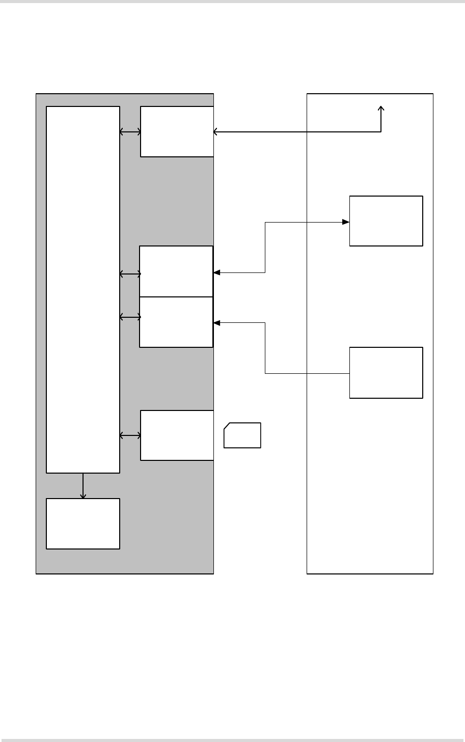
3.2 Block Diagram
Figure 3 shows a block diagram of a sample configuration that incorporates a GWM400 and
typical accessories.
Figure 3: Block diagram
GWM400
ELS61-AUS
RS-232
driver
SIM card
interface
Power regulation
RF antenna
interface
LED
RF antenna interface
Host
controller
Power supply
External application
SIM
card
Antenna

GWM400 Product Technical Specification and User Guide
3.3 Operating Modes
25
GWM400_HID_v02 2017-07-05
Confidential / Prelimenary
Page 20 of 38
3.3 Operating Modes
The table below briefly summarizes the various operating modes referred to in the following
chapters.
Table 9: Overview of operating modes
Normal operation UMTS / HSPA / LTE
SLEEP
Power saving set automatically when no call is in prog-
ress.
UMTS / HSPA / LTE
IDLE
Power saving disabled, but no call in progress.
UMTS DATA UMTS data transfer in progress. Power consumption
depends on network settings (e.g. TPC Pattern) and data
transfer rate.
HSPA DATA HSPA data transfer in progress. Power consumption
depends on network settings (e.g. TPC Pattern) and data
transfer rate.
LTE DATA LTE data transfer in progress. Power consumption
depends on network settings (e.g. TPC Pattern) and data
transfer rate.
Power Down Normal shutdown after sending the power down command. Only a voltage regu-
lator is active for powering the RTC. Software is not active. Interfaces are not
accessible. Operating voltage remains applied.
Airplane mode Airplane mode shuts down the radio part of the module, causes the module to
log off from the network and disables all AT commands whose execution
requires a radio connection.
Airplane mode can be controlled by AT command (see [1]).
GWM400 Product Technical Specification and User Guide
3.4 Molex Microfit Connector
25
GWM400_HID_v02 2017-07-05
Confidential / Prelimenary
Page 21 of 38
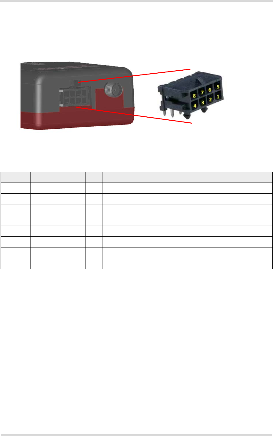
3.4 Molex Microfit Connector
Via the 8-pin Molex Microfit connector, the host application controller controls the GWM400 (in-
cluding power supply), and transports data.
Figure 4: Pin assignment Molex Microfit
The Molex Microfit connector implements an RS-232 interface (see Section 3.4.1) as well as
the power supply line (see Section 3.4.2).
The GWM400‘s Molex Microfit (3.0) connector, i.e., the header (series number: 430450822)
mates with the Molex Microfit (3.0) receptacle (series number: 430250800).
Table 10: 8-pin Molex Microfit connector
Pin no. Signal name I/O Function
1 BATT+ I Power Supply (4.75-32V DC; 3.5W maximum including peaks)
2 DTR0 I Data Terminal Ready
3 RXD0 O Receive Data
4 CTS0 O Clear To Send
5 DCD0 O Data Carrier Detected
6 GND - Ground
7 TXD0 I Transmit Data
8 RTS0 I Request To Send

GWM400 Product Technical Specification and User Guide
3.4 Molex Microfit Connector
25
GWM400_HID_v02 2017-07-05
Confidential / Prelimenary
Page 22 of 38
3.4.1 RS-232 Interface
The RS-232 interface is implemented as a serial asynchronous transmitter and receiver con-
forming to ITU-T V.24 Interchange Circuits DCE. Based on the conventions for DCE-DTE con-
nections it communicates with the host application (DTE) using the following signals:
• Port TxD @ application sends data to TXD0 of the GWM400
• Port RxD @ application receives data from RXD0 of the GWM400
The serial interface (also called ASC0) is configured for 8 data bits, no parity and 1 stop bit, and
is by default operated at a fixed baud rate of 9600bps, but can be configured for bit rates from
1200bps to 921kbps. Autobauding supports bit rates from 1.2kbps to 230kbps. Hardware hand-
shake using the RTS0 and CTS0 signals and XON/XOFF software flow control are supported.
In addition, the modem control signals DTR0 and DCD0 are available. There are different
modes of operation that can be set with AT commands.
3.4.2 Power Supply
The power supply of the GWM400 has to be a single voltage source of VPLUS=4.75V…32V ca-
pable of providing a peak current of about 368 mA at 15V during an active transmission. The
uplink burst causes strong ripple (drop) on the power lines. The absolute minimum voltage
during drops must be >4.75V.

GWM400 Product Technical Specification and User Guide
3.5 Power Up/Power Down Scenarios
25
GWM400_HID_v02 2017-07-05
Confidential / Prelimenary
Page 23 of 38
3.5 Power Up/Power Down Scenarios
In general, be sure not to turn on the GWM400 while it is beyond the safety limits of voltage
stated in Section 4.1. GWM400 immediately switches off after having started and detected
these inappropriate conditions. In extreme cases this can cause permanent damage to the
GWM400.
3.5.1 Turn GWM400 on
GWM400 is automatically turned on and started into normal mode by plugging or by re-plug-
ging an appropriate power supply unit at the power supply line BATT+.
Every time before turn on the GWM400, it must be disconnected at least for 2 seconds from
power supply to ensure turn on properly.
3.5.2 Reset/Restart GWM400
GWM400 can be reset/restarted by entering the command AT+CFUN=x,1. For details on
AT+CFUN please see [1].
3.5.3 Turn GWM400 off
Normal shutdown:
• To turn off the GWM400 use the AT^SMSO command, rather than disconnecting the mains
adapter.
This switch off procedure lets the GWM400 log off from the network and allows the software
to enter a secure state and save data before disconnecting the power supply. After
AT^SMSO has been entered the GWM400 returns the following result codes:
^SMSO: MS OFF
OK
^SHUTDOWN
The "^SHUTDOWN" result code indicates that the GWM400 turns off in less than 1 second.
After the shutdown procedure is complete the GWM400 enters the Power Down mode. The
RTC is still fed from the voltage regulator in the power supply ASIC.
Only after power off and power on again, i.e., turning off and on the power supply line, can the
terminal be switches on again. Apart from the normal shutdown.
3.5.4 Disconnecting Power Supply
Before disconnecting the power supply from the BATT+ pin, make sure that the GWM400 is in
a safe condition. The best way is to wait 1s after the "^SHUTDOWN" result code has been in-
dicated.
GWM400 Product Technical Specification and User Guide
3.6 SIM Interface
25
GWM400_HID_v02 2017-07-05
Confidential / Prelimenary
Page 24 of 38
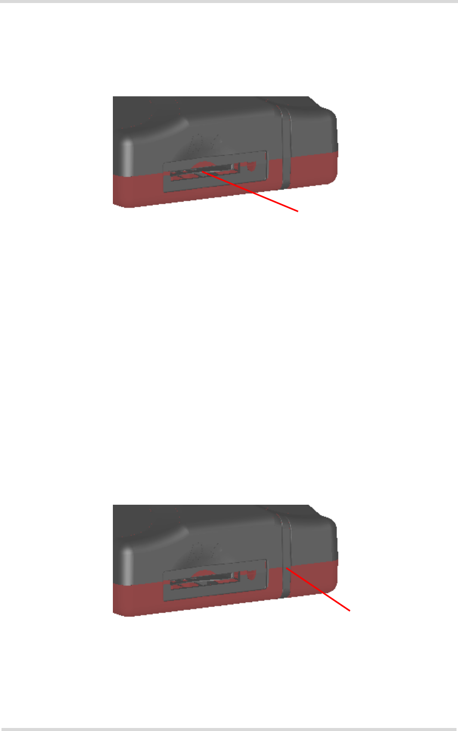
3.6 SIM Interface
The SIM interface is intended for 1.8V and 3V SIM cards in accordance with 3GPP 31.102. The
card holder is a five wire interface according to ETSI 102 221. The SIM card holder is protected
by a rubber cover that has to be opened before a SIM can be inserted.
Figure 5: SIM interface
The SIM - with the circuit side facing upwards - is inserted by gently pushing it into the SIM card
holder until it snaps hold. It is now protected from accidental removal. The SIM can be removed
from the card holder by using a flat object such as a screwdriver to carefully press the inserted
SIM until it snaps out again.
All signals of the SIM interface are protected from electrostatic discharge.
Removing and inserting the SIM card during operation requires is not supported by GWM400.
Note: No guarantee can be given, nor any liability accepted, if loss of data is encountered after
removing the SIM card during operation. Also, no guarantee can be given for properly initializ-
ing any SIM card that the user inserts after having removed a SIM card during operation. In this
case, the application must restart the GWM400.
3.7 Status LED
GWM400 has a green LED to indicate its operating status.
Figure 6: Status LED
The LED is enabled by default, but can be configured by AT command AT^SLED. For more
information on the AT^SLED command please refer to [1].
SIM card reader
Status LED
GWM400 Product Technical Specification and User Guide
3.8 RF Antenna Interface
25
GWM400_HID_v02 2017-07-05
Confidential / Prelimenary
Page 25 of 38
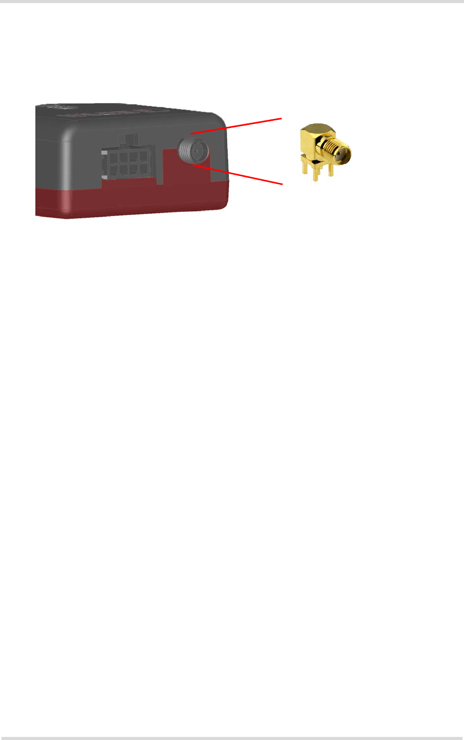
3.8 RF Antenna Interface
An external RF antenna is connected via the GWM400’s SMA connector (jack) that is also the
antenna reference point (ARP).
Figure 7: Antenna connector
The system impedance is 50. In any case, for good RF performance, the return loss of the
customer application’s antenna should be better than 10dB (VSWR < 2). GWM400 withstand
a total mismatch at this connector when transmitting with maximum RF power.
Additional ESD protection to the antenna connector is provided. DC voltage must not be ap-
plied to the antenna circuit to protect it from damage.
Please note that the terminal should be installed and operated with a minimum distance of
20cm between the antenna connected to the terminal and any human bodies. Also, the trans-
mitter must not be co-located or operating in conjunction with any other antenna or transmitter.
For mobile and fixed operation configurations the antenna gain, including cable loss, must not
exceed the limit 2.51 dBi for all the supported bands.
The antenna's character impedance should be 50. It it recommended that the antenna should
have VSWR <=2:1, within the working band frequency range.
SMA connector (jack)

GWM400 Product Technical Specification and User Guide
4 Electrical and Environmental Characteristics
30
GWM400_HID_v02 2017-07-05
Confidential / Prelimenary
Page 26 of 38
4 Electrical and Environmental Characteristics
4.1 Absolute Maximum Ratings
Table 11: Absolute maximum ratings
Parameter Port / Description Min. Max. Unit
Supply voltage BATT+ -0.3 +45 V
RS-232 input voltage range TXD0, DTR0, RTS0 -25 +25 V
RS-232 output voltage
range
RXD0, CTS0, DCD0 -13.2 +13.2 V
Immunity against discharge
of static electricity
All interfaces (lines)
Contact discharge
Air discharge
-4
-8
+4
+8
kV
kV
Table 12: Operating supply voltage for GWM400
Parameter Min Typ Max Unit
Supply voltage BATT+
measured at Molex Microfit
4.75 15 32 V
GWM400 Product Technical Specification and User Guide
4.2 Power Supply Ratings
30
GWM400_HID_v02 2017-07-05
Confidential / Prelimenary
Page 27 of 38
4.2 Power Supply Ratings
Table 13: Power supply specification
Description Conditions Typical rating Unit
IBATT+
1
(i.e., sum of
BATT+BB and
BATT+RF)
1. With an impedance of ZLOAD=50Ω at the antenna pad.
All measurements have been done with BATT+ = 15V.
OFF State supply
current
Power Down 13.6 mA
Peak current UMTS Max output power 254 mA
LTE Max output power 368 mA
Average UMTS
supply current
Data transfer @
maximum Pout
IDLE @ DRX=6
(UART active, but no communication)
16.5 mA
UMTS Data transfer Band I; +23dBm 214 mA
UMTS Data transfer Band V; +23dBm 163 mA
UMTS Data transfer Band VIII; +23dBm 195 mA
HSPA Data transfer Band I; +23dBm 210 mA
HSPA Data transfer Band V; +23dBm 163 mA
HSPA Data transfer Band VIII; +23dBm 194 mA
Average LTE sup-
ply current
Data transfer @
maximum Pout
IDLE 2
(UART active, but no communication)
2. The power save mode is disabled via AT command AT^SCFG=”MEopMode/PwrSave”,”disabled”
18.6 mA
LTE Data transfer Band 33; +23dBm
3. Communication tester settings:
- Channel Bandwidth: 5MHz
- Number of Resource Blocks: 25 (DL), 1 (UL), RB position: Low
- Modulation: QPSK
238 mA
LTE Data transfer Band 53; +23dBm 168 mA
LTE Data transfer Band 83; +23dBm 206 mA
LTE Data transfer Band 283; +23dBm 196 mA

GWM400 Product Technical Specification and User Guide
4.3 Operating Temperatures
30
GWM400_HID_v02 2017-07-05
Confidential / Prelimenary
Page 28 of 38
4.3 Operating Temperatures
Note: Within the specified normal operating temperature range the board temperature may
vary to a great extent depending on operating mode, used frequency band, radio output power
and current supply voltage. Note also the differences and dependencies that usually exist be-
tween board (PCB) temperature of the GWM400 and its ambient temperature.
Table 14: Temperature characteristics
Parameter Min Typical Max Unit
Normal operation (ambient temperature) -30 +75 °C

GWM400 Product Technical Specification and User Guide
4.4 Antenna Interface
30
GWM400_HID_v02 2017-07-05
Confidential / Prelimenary
Page 29 of 38
4.4 Antenna Interface
Table 15 lists RF antenna interface specifications for the GWM400. Please note that the spec-
ified conditions may not apply to or be supported by all terminals.
Table 15: RF Antenna interface UMTS/LTE
Parameter Conditions Min. Typical Max. Unit
UMTS/HSPA connectivity Band I,V,VIII
Receiver Input Sensitiv-
ity@ARP
UMTS 2100 Band I -106.7 dBm
UMTS 850 Band V -106.7 dBm
UMTS 900 Band VIII -103.7 dBm
UMTS Maximum TX Power1
1. RF Power@ ARP with 50 Ohm Load, ambient temperature 25°C
UMTS 2100 Band I 21 23 - dBm
UMTS 850 Band V 21 23 - dBm
UMTS 900 Band VIII 21 23 - dBm
LTE connectivity Band 3, 5, 8, 28
LTE Receiver Input Sensitiv-
ity (5 MHz@ ARP, single
antenna)
LTE FDD 1800 Band 3 -96.3 -98 dBm
LTE FDD 850 Band 5 -97.3 -100 dBm
LTE FDD 900 Band 8 -96.3 -100 dBm
LTE FDD 700 Band 28 -97.8 -98 dBm
LTE Maximum TX Power2
2. Power @ ARP with 50Ohm Load ambient temperature 25°C, 5MHz BW, 1R, Position Low
LTE FDD 1800 Band 3 +21 +22.5 dBm
LTE FDD 850 Band 5 +21 +22.5 dBm
LTE FDD 900 Band 8 +21 +22.5 dBm
LTE FDD 700 Band 28 +21 +22.5 dBm

GWM400 Product Technical Specification and User Guide
4.5 Storage Conditions
30
GWM400_HID_v02 2017-07-05
Confidential / Prelimenary
Page 30 of 38
4.5 Storage Conditions
The conditions stated above are only valid for devices in their original packed state in weather
protected, non-temperature-controlled storage locations. Normal storage time under these
conditions is 12 months maximum.
Table 16: Storage conditions
Type Condition Unit Reference
Air temperature: Low
High
-25
+40
°C IPC/JEDEC J-STD-033A
Humidity relative: Low
High
10
90 at 40°C
%---
IPC/JEDEC J-STD-033A
Air pressure: Low
High
70
106
kPa IEC TR 60271-3-1: 1K4
IEC TR 60271-3-1: 1K4
Movement of surrounding air 1.0 m/s IEC TR 60271-3-1: 1K4
Water: rain, dripping, icing and
frosting
Not allowed --- ---
Radiation: Solar
Heat
1120
600
W/m2ETS 300 019-2-1: T1.2, IEC 60068-2-2 Bb
ETS 300 019-2-1: T1.2, IEC 60068-2-2 Bb
Chemically active substances Not
recommended
IEC TR 60271-3-1: 1C1L
Mechanically active substances Not
recommended
IEC TR 60271-3-1: 1S1
Vibration sinusoidal:
Displacement
Acceleration
Frequency range
1.5
5
2-9 9-200
mm
m/s2
Hz
IEC TR 60271-3-1: 1M2
Shocks:
Shock spectrum
Duration
Acceleration
semi-sinusoidal
1
50
ms
m/s2
IEC 60068-2-27 Ea
GWM400 Product Technical Specification and User Guide
5 Mechanics, Mounting and Packaging
33
GWM400_HID_v02 2017-07-05
Confidential / Prelimenary
Page 31 of 38
5 Mechanics, Mounting and Packaging
5.1 Mechanical Dimensions
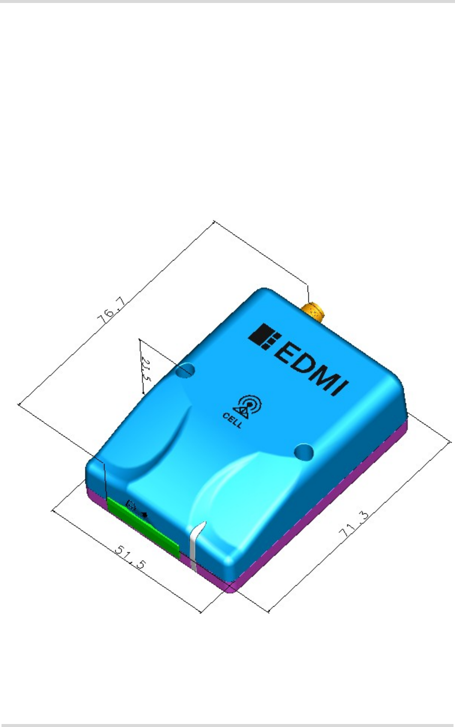
Figure 8 shows a 3D view of the GWM400 and provides an overview of the mechanical dimen-
sions of the terminal. For further details and an exploded view see Figure 9.
Figure 8: GWM400 3D overview
Length: 71.3mm (excluding SMA antenna connector)
76.7mm (including SMA antenna connector)
Width: 51.5mm
Height: 23.5mm
GWM400 Product Technical Specification and User Guide
5.1 Mechanical Dimensions
33
GWM400_HID_v02 2017-07-05
Confidential / Prelimenary
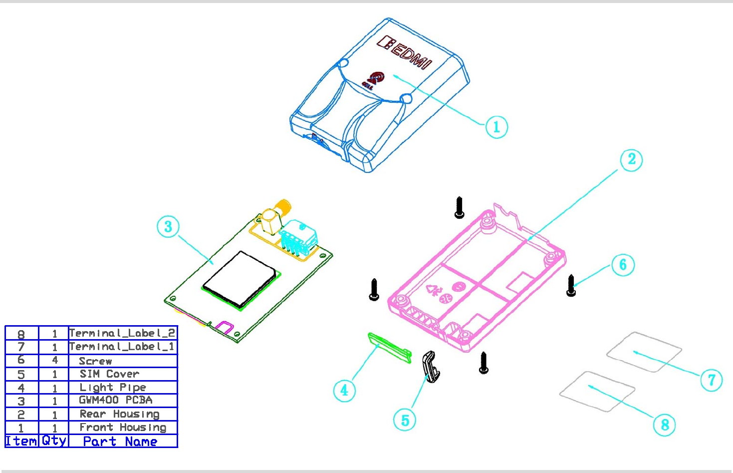
Page 32 of 125
Figure 9: GWM400 exploded view
GWM400 Product Technical Specification and User Guide
5.2 Packaging
33
GWM400_HID_v02 2017-07-05
Confidential / Prelimenary
Page 33 of 38
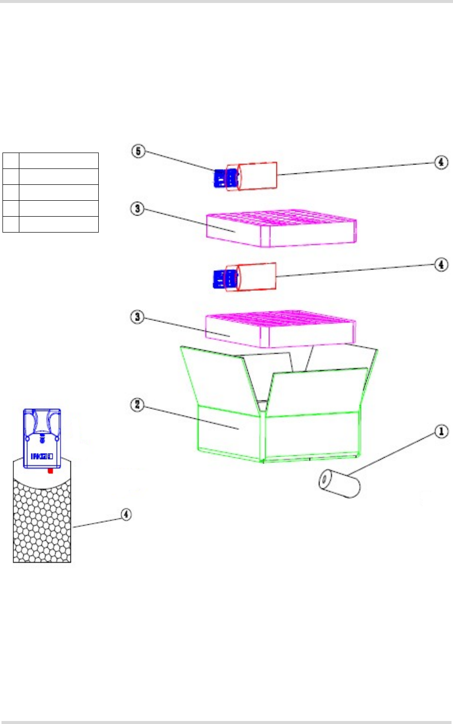
5.2 Packaging
GWM400 terminal units come in bubble bags stashed into VP boxes made out of corrugated
fiberboard:
• VP box size: 370mm x 350mm x 155mm
A VP box contains up to 60 terminal units, stashed into two layers of up to 30 units. Terminal
layers are separated by foam layers for protective purposes.
Figure 10: Packaging of GWM400
1 475.00241.005
2 VP box
3FOAMGWM400
4 G-BUBBLEBAG
5GWM400
GWM400 Product Technical Specification and User Guide
6 Full Type Approval
36
GWM400_HID_v02 2017-07-05
Confidential / Prelimenary
Page 34 of 38
6 Full Type Approval
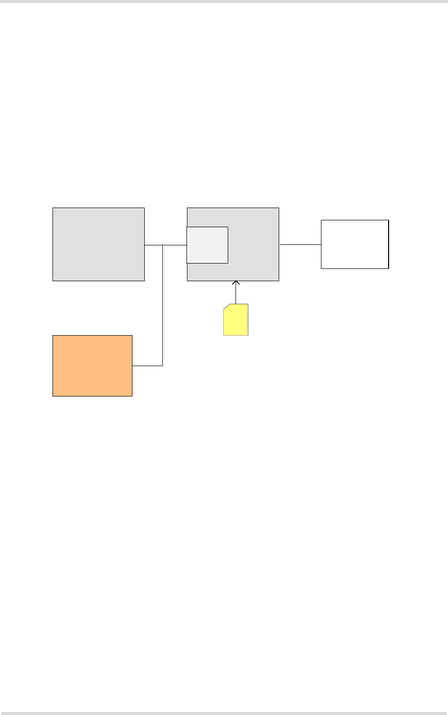
6.1 Gemalto M2M Reference Setup
The Gemalto M2M reference setup submitted to type approve GWM400 consists of the follow-
ing components:
• GWM400 with approved Java module
•PC as MMI
• Power Supply
• RS-232/power supply cable (modified from DB9-RJ45 connector adapter)
Figure 11: Reference equipment for approval
For ordering information please refer to Chapter 7.
PC
Power supply
SIM
RS-232/
power
supply
Antenna
or
50Ohm cable
to the
system simulator
8-pin
Microfit
Connector
Terminal

GWM400 Product Technical Specification and User Guide
6.2 Restrictions
36
GWM400_HID_v02 2017-07-05
Confidential / Prelimenary
Page 35 of 38
6.2 Restrictions
Later enhancements and modifications beyond the certified configuration require extra approv-
als. Each supplementary approval process includes submittal of the technical documentation
as well as testing of the changes made.
• No further approvals are required for customer applications that comply with the approved
GWM400 configuration.
• Extra approval must be obtained for applications using other accessories than those
included in the approved GWM400 configuration (power supply, MMI implementation sup-
ported by AT commands).
6.3 CE Conformity
GWM400 meets the requirements of the EU directives listed below:
• Radio Equipment Directive (RED) 2014/53/EU
GWM400 is marked with the CE conformity mark.
6.4 EMC
GWM400 complies with the equipment requirements specified in EN 301489-1 and -52 are
covered by the Radio Equipment Directive. For details see Section 1.3.

GWM400 Product Technical Specification and User Guide
6.5 Compliance with FCC Rules and Regulations
36
GWM400_HID_v02 2017-07-05
Confidential / Prelimenary
Page 36 of 38
6.5 Compliance with FCC Rules and Regulations
As an integrated product, GWM400 is fully compliant with the grant of the FCC Equipment
Authorization for the built-in Java modules, and therefore, bears the labels “Contains FCC ID:
QIPELS61-AUS”.
The Equipment Authorization Certification for GWM400 is listed under the following identifiers:
FCC Idenitifier: QIPGGWM400
Granted to Gemalto M2M GmbH
Notes (FCC):
Radio frequency radiation exposure Information:
This equipment complies with FCC radiation exposure limits set forth for an uncontrolled envi-
ronment. This equipment should be installed and operated with minimum distance of 20 cm be-
tween the radiator and your body. This transmitter must not be co-located or operating in
conjunction with any other antenna or transmitter.
This device complies with part 15 of the FCC Rules. Operation is subject to the following two
conditions: (1) This device may not cause harmful interference, and (2) this device must accept
any interference received, including interference that may cause undesired operation.
This terminal equipment has been tested and found to comply with the limits for a Class B dig-
ital device, pursuant to Part 15 of the FCC Rules. These limits are designed to provide reason-
able protection against harmful interference in a residential installation. This equipment
generates, uses and can radiate radio frequency energy and, if not installed and used in accor-
dance with the instructions, may cause harmful interference to radio communications. Howev-
er, there is no guarantee that interference will not occur in a particular installation. If this
equipment does cause harmful interference to radio or television reception, which can be de-
termined by turning the equipment off and on, the user is encouraged to try to correct the inter-
ference by one or more of the following measures:
• Reorient or relocate the receiving antenna.
• Increase the separation between the equipment and receiver.
• Connect the equipment into an outlet on a circuit different from that to which the receiver is
connected.
• Consult the dealer or an experienced radio/TV technician for help.
Changes or modifications made to this equipment not expressly approved by Gemalto M2M
may void the FCC authorization to operate this equipment.
Users and installers must be provided with antenna installation instructions and transmitter op-
erating conditions for satisfying RF exposure compliance: For more information on the RF an-
tenna interface please refer to Section 3.8 and Section 4.4.

GWM400 Product Technical Specification and User Guide
7 List of Parts and Accessories
37
GWM400_HID_v02 2017-07-05
Confidential / Prelimenary
Page 37 of 38
7 List of Parts and Accessories
Table 17: List of parts and accessories
Description Supplier Ordering information
GWM400 Gemalto Ordering number
L30960-N4300-A200
8-pin receptacle
Molex Microfit (3.0)
Molex Ordering number
43025-0800

38
M2M.GEMALTO.COM
About Gemalto
Gemalto (Euronext NL0000400653 GTO) is the world leader in digital security with 2015 annual
revenues of €3.1 billion and blue-chip customers in over 180 countries. Our 14,000+ employees
operate out of 118 offices, 45 personalization and data centers, and 27 research and software
development centers located in 49 countries.
We are at the heart of the rapidly evolving digital society. Billions of people worldwide increasingly
want the freedom to communicate, travel, shop, bank, entertain and work - anytime, everywhere
- in ways that are enjoyable and safe. Gemalto delivers on their expanding needs for personal
mobile services, payment security, authenticated cloud access, identity and privacy protection,
eHealthcare and eGovernment efficiency, convenient ticketing and dependable machine-to-
machine (M2M) applications.
Gemalto develops secure embedded software and secure products which we design and
personalize. Our platforms and services manage these secure products, the confidential data they
contain and the trusted end-user services they enable. Our innovations enable our clients to offer
trusted and convenient digital services to billions of individuals.
Gemalto thrives with the growing number of people using its solutions to interact with the digital
and wireless world.
For more information please visit
m2m.gemalto.com, www.facebook.com/gemalto, or Follow@gemaltom2m on twitter.
Gemalto M2M GmbH
Werinherstrasse 81
81541 Munich
Germany
© Gemalto 2017. All rights reserved. Gemalto, the Gemalto logo, are trademarks and service marks of Gemalto and are registered in certain countries. April 2013