THALES DIS AlS Deutschland HC25 GSM/GPRS/EDGE/UMTS/HSDPA MODULE User Manual HC25 Hardware Interface Overview
Gemalto M2M GmbH GSM/GPRS/EDGE/UMTS/HSDPA MODULE HC25 Hardware Interface Overview
UserManual.wiki
>
THALES DIS AlS Deutschland
>
HC25 User Manual
User Manual
Navigation menu
Upload a User Manual
Namespaces
Wiki Guide
HTML
PDF
Info
Views
User Manual
Discussion / Help
Navigation
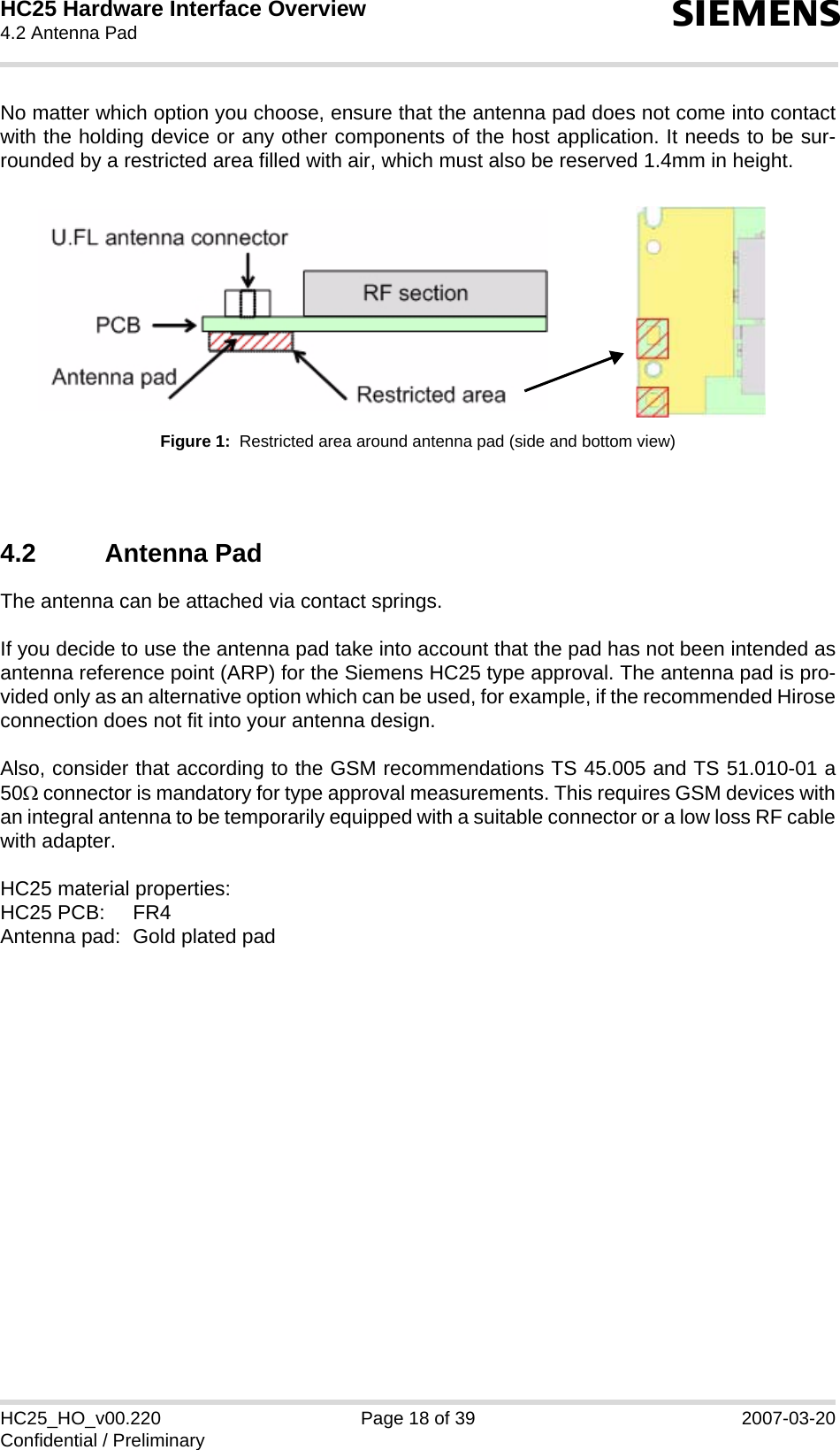
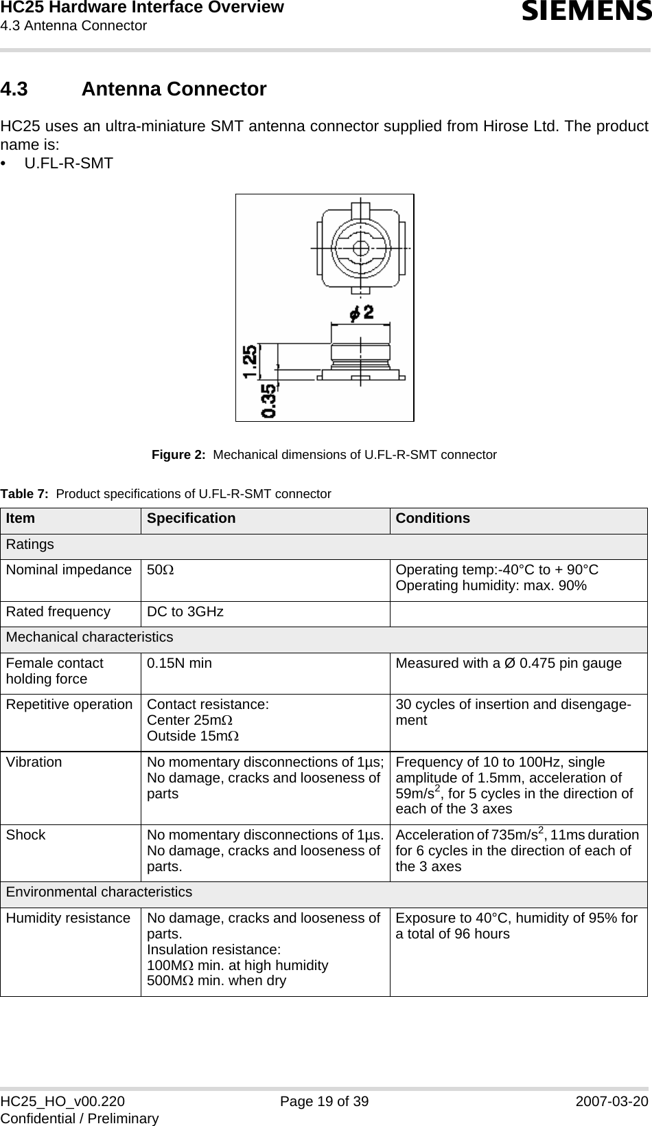
![HC25 Hardware Interface Overview1 Introduction12sHC25_HO_v00.220 Page 6 of 39 2007-03-20Confidential / Preliminary1 IntroductionThis document describes the hardware of the Siemens HC25 module that connects to the cel-lular device application and the air interface. It helps you quickly retrieve interface specifica-tions, electrical and mechanical details and information on the requirements to be consideredfor integrating further components. 1.1 Related Documents[1] HC25 AT Command Set 00.220[2] HC25 Release Notes 00.2201.2 Terms and AbbreviationsAbbreviation DescriptionANSI American National Standards InstituteAMR Adaptive MultirateARP Antenna Reference PointB2B Board-to-board connectorBB BasebandBEP Bit Error ProbabilityBTS Base Transceiver StationCB or CBM Cell Broadcast MessageCE Conformité Européene (European Conformity)CS Coding SchemeCS Circuit SwitchedCSD Circuit Switched DataDAC Digital-to-Analog ConverterdBm0 Digital level, 3.14dBm0 corresponds to full scale, see ITU G.711, A-lawDCS Digital Cellular SystemDL DownloadDRX Discontinuous ReceptionDSB Development Support BoardDSP Digital Signal ProcessorDTMF Dual Tone Multi FrequencyDTX Discontinuous TransmissionEDGE Enhanced Data rates for GSM EvolutionEFR Enhanced Full RateEGSM Enhanced GSM](https://usermanual.wiki/THALES-DIS-AlS-Deutschland/HC25/User-Guide-771663-Page-6.png)
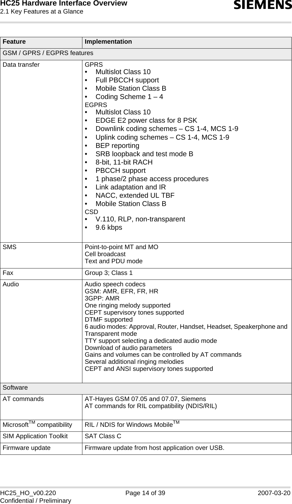
![HC25 Hardware Interface Overview2 Product Concept15sHC25_HO_v00.220 Page 13 of 39 2007-03-20Confidential / Preliminary2 Product Concept2.1 Key Features at a GlanceFeature ImplementationGeneralFrequency bands UMTS/HSDPA: Triple band, 850//1900/2100MHzGSM/GPRS/EDGE: Quad band, 850/900/1800/1900MHzGSM class Small MSOutput power(according to Release 99)Class 4 (+33dBm ±2dB) for EGSM850Class 4 (+33dBm ±2dB) for EGSM900Class 1 (+30dBm ±2dB) for GSM1800Class 1 (+30dBm ±2dB) for GSM1900Class E2 (+27dBm ± 3dB) for GSM 850 8-PSKClass E2 (+27dBm ± 3dB) for GSM 900 8-PSKClass E2 (+26dBm +3 /-4dB) for GSM 1800 8-PSKClass E2 (+26dBm +3 /-4dB) for GSM 1900 8-PSKClass 3 (+24dBm +1/-3dB) for UMTS 2100, WCDMA FDD BdIClass 3 (+24dBm +1/-3dB) for UMTS 1900,WCDMA FDD BdIIClass 3 (+24dBm +1/-3dB) for UMTS 850, WCDMA FDD BdVPower supply 3.2V < VBATT+ < 4.2VPhysical Dimensions: 50mm x 34mm x 4.5mmWeight: approx. 10gRoHS All hardware components fully compliant with EU RoHS DirectiveHSDPA features3GPP Release 5 3.6 Mbps, UL 384 kbpsUE CAT. [1-6], 11, 12 supportedCompressed mode (CM) supported according to 3GPP TS25.212UMTS featuresRelease 99, June 2004, W-CDMA FDD standard PS data rate – 384 kbps DL / 384 kbps ULCS data rate – 64 kbps DL / 64 kbps UL](https://usermanual.wiki/THALES-DIS-AlS-Deutschland/HC25/User-Guide-771663-Page-13.png)