THAMES and KOSMOS 620141 Kosmobits / Code Gamer User Manual
THAMES & KOSMOS, LLC. Kosmobits / Code Gamer Users Manual
UserManual.wiki
>
THAMES and KOSMOS
>
620141 User Manual
>
Users Manual
Contents
1.
Users Manual
2.
Users Manual - German version
Users Manual
Navigation menu
Upload a User Manual
Namespaces
Wiki Guide
HTML
PDF
Info
Views
User Manual
Discussion / Help
Navigation

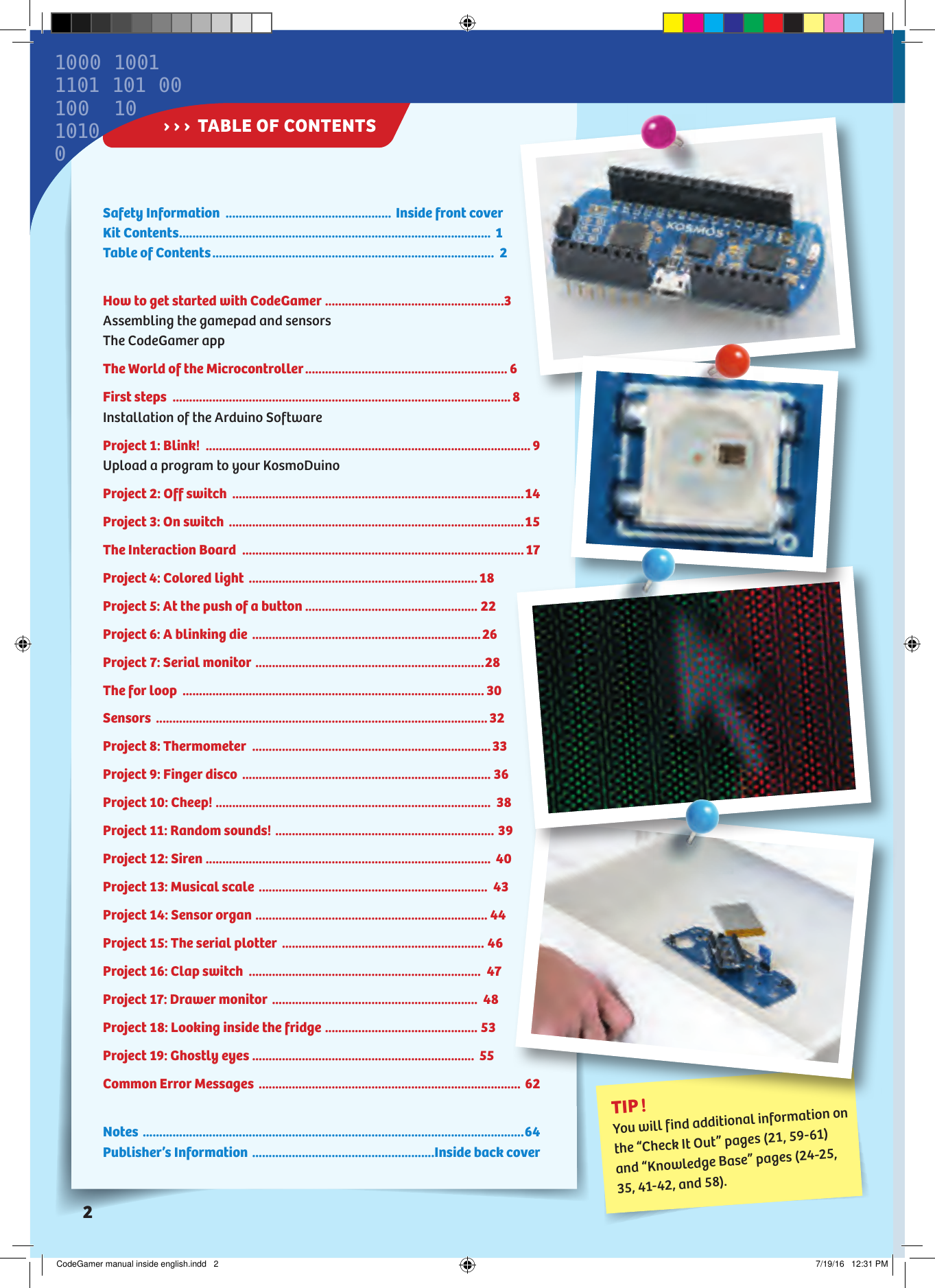
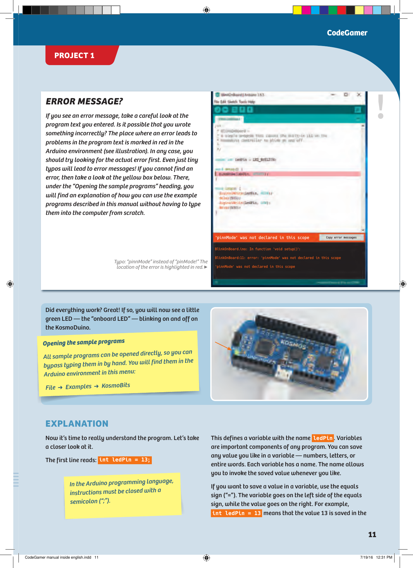


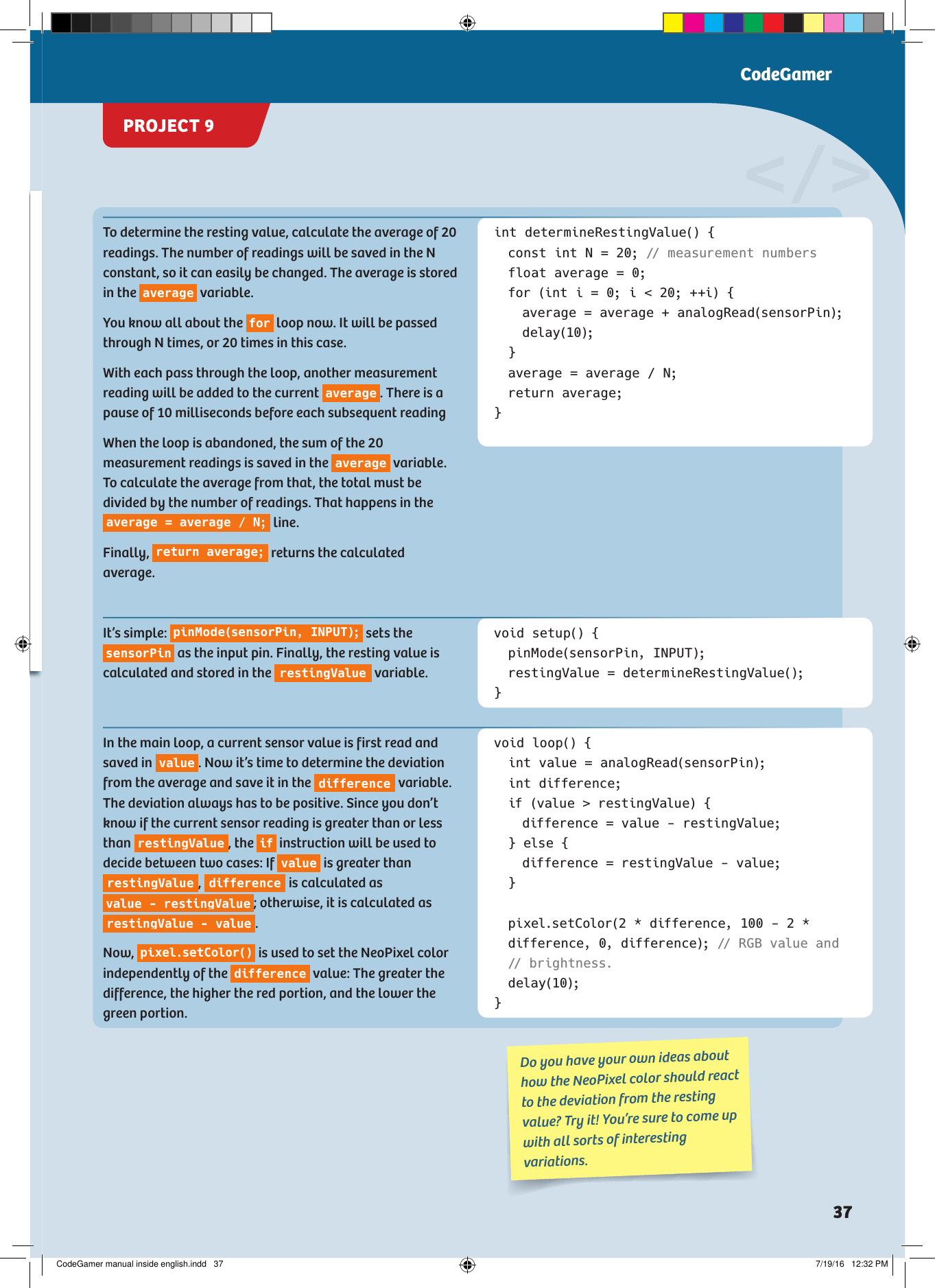
![ArraysIf you want to save a lot of values of the same type, for example the last 100 values, it can be pretty time-consuming and confusing to have to enter all that in. You would have to apply a separate variable for each individual value, as follows:int value 1;int value 2;int value 3;...e t c...int value 100;It’s a lot simpler to use what’s called an array.In an array, you can store many values at one time. To make it possible to access the individual variables in the array, they are all consecutively numbered. So you can think of an array as a kind of table in which the individual values are entered into numbered columns. The numbering of the columns, however, starts with 0 rather than 1:INDEX 0 1 2 3 … nVALUES Value 0 Value 1 Value 2 Value 3 … Value nIn general, an array is created as follows:type arrayName[length];You can also assign values to an array by specifying the individual values in curly brackets: The type specifies which type of data can be saved in the array (int, float, etc.). The number of values that can be stored in an array is known as its length. int myArray[10]; // An array that can // take 10 int valuesint myArray[4] = {0, 4, 2, 3};In that case, you don’t necessarily have to indicate how many values there are. You can also write: int myArray[] = {0, 4, 2, 3};So, for example, to create an array that can take 10 integer values, you proceed as follows: KNOWLEDGE BASEAn array is sometimes called a Field or Data Field. However the term Array is the much more common name.CodeGamerCodeGamer manual inside english.indd 41 7/19/16 12:32 PM](https://usermanual.wiki/THAMES-and-KOSMOS/620141.Users-Manual/User-Guide-3149685-Page-43.png)
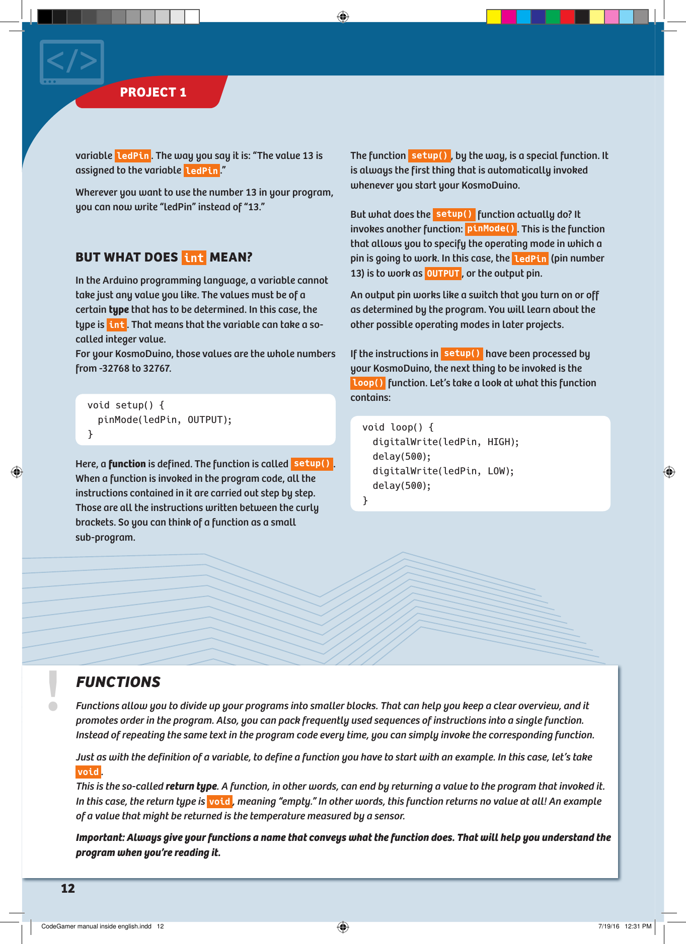
![You will often want all individual values to be set to zero. You can do that quickly by writing as follows: int myArray[10] = {}; // Array of // length 10 with all the values // set to 0.To access the individual values of an array, you indicate the value in square brackets for the index that you want to access. So if you think of the array as a table, the index corresponds to the column number.int myArray[100] = {}; // Array of // length 100 with all values set to 0.myArray[2] = 42; // The value at index // position 2 is now 42.int x = myArray[2]; // x contains the // value saved at index position 2// in myArray, in this case it is 42.You may often want to calculate a new value from all the individual ones, for example the sum of all individual values. Since you can now address the individual values via their index, you can easily do this with a for loop:// values is an array of length 100.int sum = 0;for (int index = 0; index < 100; ++index) { sum = sum + values[index];}With the first pass through the loop, the value values[0] is added to sum. Then, index is raised by 1, and the next value is added. This is repeated until the last value (valu es[99]) has been added. In the next project, you will use an array to play a musical scale.!NOTE!Since the index for the first value is 0 rather than 1, the highest possible index for an array of length N is not N, but rather N-1. With an array of length 100, in other words, the highest possible index would be 99. If you use a higher index, it will result in an error in the program sequence. It’s impossible to predict what would happen then. So be careful only to use valid values for the index. KNOWLEDGE BASECodeGamer manual inside english.indd 42 7/19/16 12:32 PM](https://usermanual.wiki/THAMES-and-KOSMOS/620141.Users-Manual/User-Guide-3149685-Page-44.png)
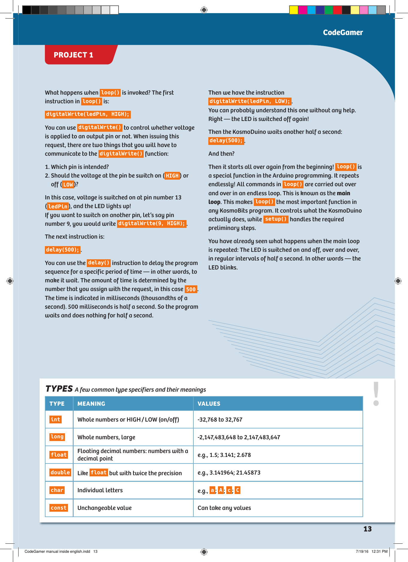
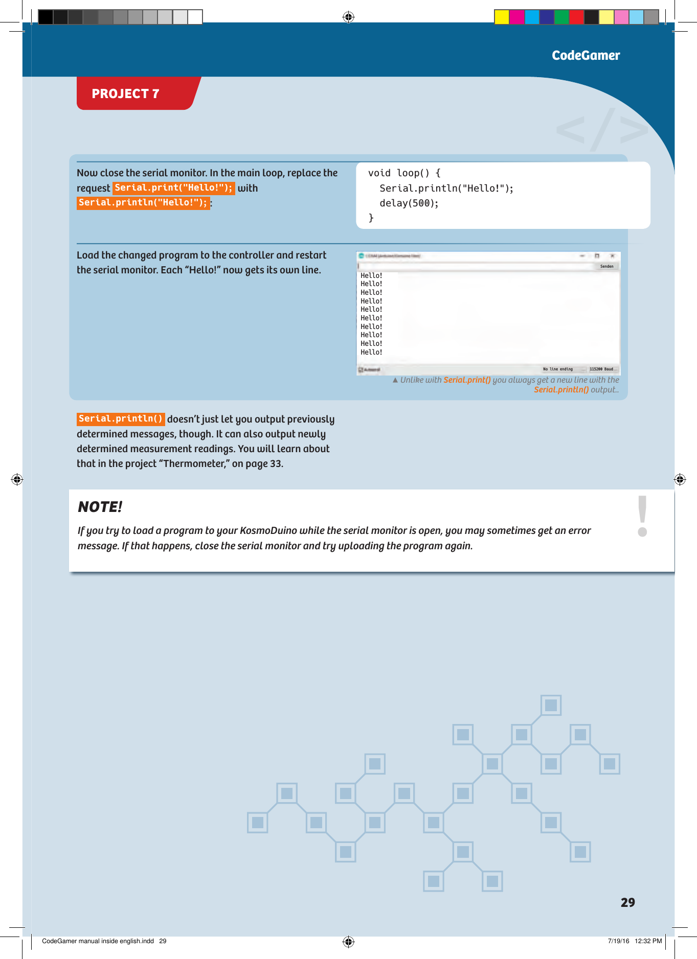
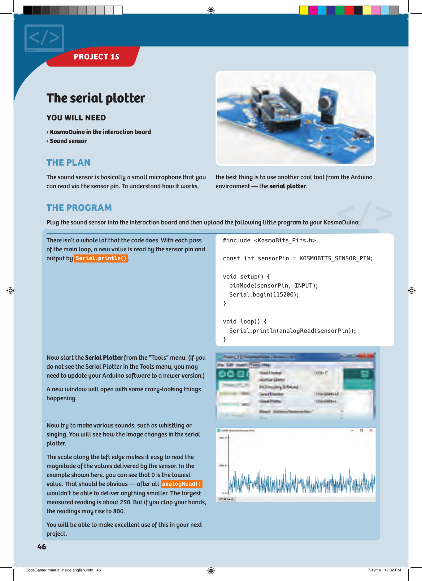
![</>Musical scaleYOU WILL NEED › KosmoDuino in the interaction boardTHE PLANYour KosmoDuino will play a musical scale.THE PROGRAMFirst you include the KosmoBits_Pins.h file and define the buzzerPin and freqRoot constants. Finally, you apply the scale[] array, in which the frequency relationships of the notes of a major-key scale will be placed. To determine the frequency of a note, you will have to multiply the corresponding value by the frequency of the root chord.#include <KosmoBits_Pins.h>const int buzzerPin = KOSMOBITS_BUZZER_PIN;const int freqRoot = 220; // This is the // note A (one octave deeper than the standard // pitch A from project 10).float scale[] = {1.f, 9.f/8, 5.f/4, 4.f/3, 3.f/2, 5.f/ 3, 15.f/8, 2.f};void setup() { for (int i = 0; i < 8; ++i) { tone(buzzerPin, scale[i] * freqRoot); delay(5 00); } noTone(buzzerPin);}void loop() { // Nothing is done here.}This time, everything is happening in s e t u p () . In the forloop, the variable i is counted up from 0 to 7. For each value of i then, the i-th note of the scale is output withtone(buzzerPin, scale[i] * freqRoot); . As described above, the frequency of the root chord freqRoot is multiplied by the corresponding frequency relationship s c al e[i] to determine the right frequency.After a pause, the for loop is passed through again until the highest note of the scale is reached. Then it’s quiet: noTone(buzzerPin); .This time, nothing is done in the main loop. The scale is just played through a single time, in other words. To make the scale play again, you can press the reset button on the KosmoDuino. That will reset the code and carry it out again from the beginning.PROJECT 13CodeGamerCodeGamer manual inside english.indd 43 7/19/16 12:32 PM](https://usermanual.wiki/THAMES-and-KOSMOS/620141.Users-Manual/User-Guide-3149685-Page-45.png)
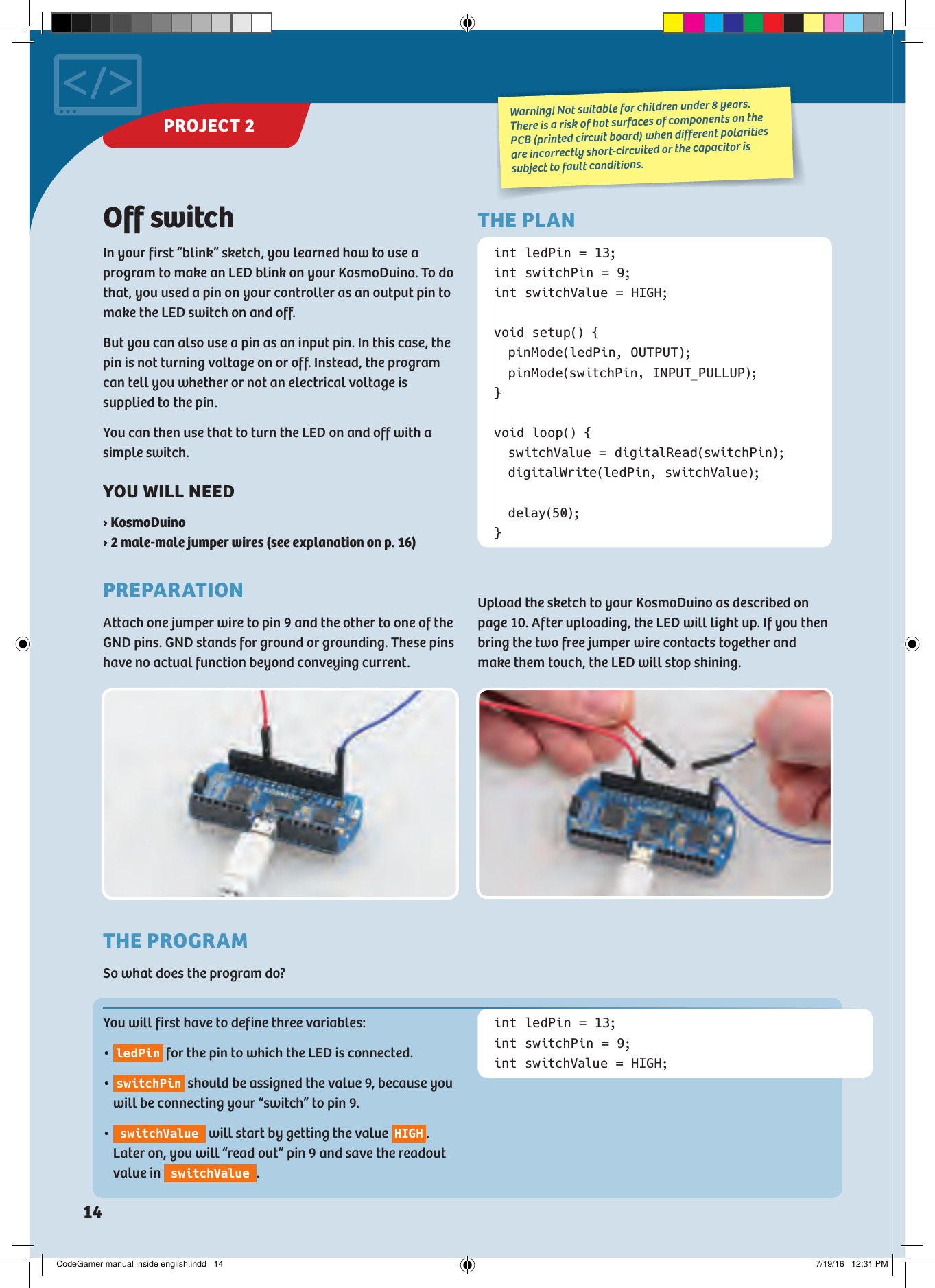
![Sensor organNow that you have learned how to play musical scales, it’s time to program an actual musical instrument.YOU WILL NEED › KosmoDuino in the interaction board› Motion sensor #include <KosmoBits_Pins.h>const int sensorPin = KOSMOBITS_SENSOR_PIN;const int buzzerPin = KOSMOBITS_BUZZER_PIN;const int buttonPin = KOSMOBITS_BUTTON_2_PIN;const float scale[] = {1.f, 9.f/8, 5.f/4, 4.f/3, 3.f/2, 5.f/ 3, 15.f/8, 2.f};const int freqRoot = 220; // This is the // note A.const int measurementMin = 300;const int measurementMax = 400;const int scaling = (measurementMax - measurementMin) / 9;const int N = 10; // Number of values that // are averaged.int values[N] = {}; // Here is where the last // 10 values are stored.int index = 0;This is where each of the pin modes is set. void setup() { pinMode(sensorPin, INPUT); pinMode(buttonPin, INPUT);}void loop() { // Reads a new value from the sensor and // saves it in values[]. values[index] = analogRead(sensorPin);First, you will define a few constants for sensor pin, buzzer pin, and button pin. Then, as you did in the last project, you will apply an array for the scale as well as a constant for the root chord. With the measurementMin and measurementMax constants, you will be regulating how far the controller has to be tipped in order to play the highest or the lowest note. You can adjust these values to suit your own preferences later on. You will be using the scaling constant later on to determine the pitch from a measurement reading, dividing practically the entire measurement range into 9 portions.The motion sensor is quite sensitive, so the readings will fluctuate a little. To keep the pitch from wavering too much, you won’t be taking the last reading to measure the pitch. Instead, you will be calculating the average of 10 readings. The last 10 measurement readings will be saved in the values[] array for this purpose. All values in it will first be set to 0 by int values[N] = {}; . With the index variable, the array will be run through, starting with 0 as usual.THE PLANYou will produce musical notes at the push of a button. The pitch of the note can be changed by moving the interaction board. With a little practice, you can play an actual melody this way.</>THE PROGRAMYou will start by taking a new measurement reading and saving it in the values array at the index position. To ensure that the next measurement reading is saved at the subsequent position, ++index; raises the index by 1. If the value of N is reached, the if instruction sets index PROJECT 14CodeGamer manual inside english.indd 44 7/19/16 12:32 PM](https://usermanual.wiki/THAMES-and-KOSMOS/620141.Users-Manual/User-Guide-3149685-Page-46.png)
![Admittedly, this was a little more involved. But the results make it all worthwhile! // Raise the index by 1, so the next // value can be saved at the next location // in the values[] field. ++index; // If index == N, the field is // fully described. // index is then set to 0, so that // the oldest value // is overwritten in the next pass. if (index == N) { index = 0; } // Now the average of the last N // measurement readings is calculated. int average = 0; // Start with the value 0 // Total the measurement values. for (int i = 0; i < N; ++i) { average = average + values[i]; } // Divide the total by the number of values. average = average / N; int noteIndex = (average - measurementMin) / scaling; // noteIndex must not be less than 0 or // greater than 7: if (noteIndex < 0) { noteIndex = 0; } else if (noteIndex > 7) { noteIndex = 7; } // Output note if (digitalRead(buttonPin) == LOW) { tone(buzzerPin, scale[noteIndex] * freqRoot); delay(10); } else { noTone(buzzerPin); delay(1); }}</>back to 0. The array is filled from the beginning again.Then it’s a matter of determining the average of the last 10 measurements. To do that, the average variable is first set to 0. In the for loop, then, all the values saved in the valu e[] array are added to average . To calculate the average from that, the result has to be divided by the number of values: average = average / N; . With int noteIndex = (average - measurementMin) / scaling; , you will be determining the “note index”: Which note in the scale sequence should be played? It might happen that noteIndex has an invalid value — in other words, that it is less than 0 or greater than 7. That’s why you will be correcting it with the if-else instruction in case of doubt. Finally, the last if query checks whether the button is pushed. If so, the corresponding note is output. If not, no note is output.CodeGamerPROJECT 14CodeGamer manual inside english.indd 45 7/19/16 12:32 PM](https://usermanual.wiki/THAMES-and-KOSMOS/620141.Users-Manual/User-Guide-3149685-Page-47.png)
![You presumably forgot to close the serial monitor before trying to upload the program.1. You forgot to connect the KosmoDuino to the computer. You might also have inserted the USB cable into the interaction board’s charge socket by mistake.2. The wrong port has been set. Check Tools ➜ Port and change the port if necessary.avrdude: ser_open(): can't open device "\\.\COM4": Access is denied.avrdude: ser_open(): can't open device "\\.\COM4": The system cannot find the file specified.Low memory available, stability problems may occur.EXAMPLE:int array[1000] = {}; // That is too large!SOLUTION:SOLUTION:SOLUTION:SOLUTION:Change your program by using a smaller array.Close the serial monitor and re-upload the program.Use the USB cable to connect your computer to the KosmoDuino via the USB port.Select a different port.Your program is using almost all the microcontroller’s RAM or is even too large for it. You may have applied a large array.Not enough memory.CodeGamerCodeGamer manual inside english.indd 63 7/19/16 12:33 PM](https://usermanual.wiki/THAMES-and-KOSMOS/620141.Users-Manual/User-Guide-3149685-Page-65.png)