THAMES and KOSMOS 620141 Kosmobits / Code Gamer User Manual
THAMES & KOSMOS, LLC. Kosmobits / Code Gamer Users Manual
Contents
- 1. Users Manual
- 2. Users Manual - German version
Users Manual
EXPERIMENT MANUAL
620141-03-090816
Franckh-Kosmos Verlags-GmbH & Co. KG, Pfizerstr. 5-7, 70184 Stuttgart, Germany | +49 (0) 711 2191-0 | www.kosmos.de
Thames & Kosmos, 301 Friendship St., Providence, RI, 02903, USA | 1-800-587-2872 | www.thamesandkosmos.com
Thames & Kosmos UK Ltd, Goudhurst, Kent, TN17 2QZ , United Kingdom | 01580 212000 | www.thamesandkosmos.co.uk
CodeGamer manual cover english.indd 1 8/9/16 10:04 AM
› › › IMPORTANT INFORMATION
Safety Information
WARNING! Only for use by children aged 10 years and older.
Instructions for parents or other supervising adults are included and
have to be observed. Keep the packaging and instructions as they
contain important information.
WARNING! Not suitable for children under 3 years. Choking hazard
— small parts may be swallowed or inhaled.
Safety for Experiments with the Rechargeable Battery
››› A lithium polymer rechargeable battery is required for
the experiments. Please use only the battery supplied
with the kit!
››› The rechargeable battery is only to be charged under
adult supervision.
››› Never perform experiments using household current!
The wires are not to be inserted into socket-outlets.
The high voltage can be extremely dangerous or fatal!
››› The battery is not to be short-circuited. It could
overheat and explode!
››› Do not connect the battery’s terminals to each other.
››› The battery is to be inserted with the correct polarity.
››› Avoid deforming the battery.
››› The battery is to be removed from the toy if it is
defective.
››› Keep the kit out of the reach of small children.
››› When assembling the device and installing the
battery, follow the instructions in this manual in
order to avoid destruction of components.
Dear Parents and Supervising Adults,
This experiment kit will introduce your child to the exciting world of
programming in a fun way.
Please be available to provide your child with help, advice, and
support.
It is natural to have questions about safety. This kit meets
U.S. and European safety standards. These standards impose
obligations on the manufacturer, but also stipulate that adults
should provide their children with advice and assistance during the
experiments.
Tell your child to read all the relevant instructions and
safety information, and to keep these materials on hand for
reference. Be sure to stress the importance of following all the rules
and information when performing the experiments.
We wish your child, and of course you as well, lots of fun
and success with the experiments!
Disposal of Electrical and Electronic Components
This product’s electronic parts are reusable and, for the
sake of protecting the environment, they should not be
thrown into the regular household trash at the end of
their lifespan. Instead, they must be delivered to a
collection location for electronic waste, as
indicated by the following symbol:
Please consult your local authorities for
the appropriate disposal location.
Disposal of Battery
The battery does not belong in the
household trash! In some states and
countries, it is required by law to deliver
batteries and rechargeable batteries to a local collection
location or to a store. This will ensure that they will be
disposed of in an environmentally responsible manner.
Batteries containing hazardous substances are identified
by this image or by chemical symbols (Cd = cadmium,
Hg = mercury, Pb = lead).
Simplified EU Declaration of Conformity
Thames & Kosmos hereby declares that the KosmoBits
radio communication unit model 620141 conforms to
Directive 2014/53/EU.
The complete text of the EU conformity declaration is
available at the following Internet address: http://
thamesandkosmos.com/codegamer/declaration.pdf
Safe Handling of Electronic Components
››› Avoid contact with metallic objects and fluids of any
kind!
››› After experimenting, pack all sensitive components in
the bags provided for them and keep them together
with the other parts in the experiment kit box.
››› If the KosmoBits hardware is not to be used for a long
period of time, please disconnect the battery’s
connection wire from the interaction board.
The toy is only to be connected to Class II equipment
bearing the following symbol:
Kosmos Quality and Safety
More than one hundred years of expertise in publishing science
experiment kits stand behind every product that bears the Kosmos
name. Kosmos experiment kits are designed by an experienced
team of specialists and tested with the utmost care during
development and production. With regard to product safety, these
experiment kits follow European and US safety standards, as well
as our own refined proprietary safety guidelines. By working
closely with our manufacturing partners and safety testing labs,
we are able to control all stages of production. While the majority
of our products are made in Germany, all of our products,
regardless of origin, follow the same rigid quality standards.
1st Edition 2016
© 2016 Franckh-Kosmos Verlags-GmbH & Co. KG,
Pfizerstr. 5-7, D-70184 Stuttgart, Tel. +49 (0) 711 2191-343
This work, including all its parts, is copyright protected. Any use outside the specific limits of
the copyright law without the consent of the publisher is prohibited and punishable by law.
This applies specifically to reproductions, translations, microfilming, and storage and
processing in electronic systems and networks. We do not guarantee that all material in this
work is free from copyright or other protection.
Project management: Jonathan Felder, Marc Gänssler, Sebastian Martin
Text and experiments: Felix Homann
Product development: Steffen Rothweiler
Manual design concept: Atelier Bea Klenk, Berlin
Layout and typesetting: Michael Schlegel, komuniki, Würzburg
Illustrations: Michael Schlegel, komuniki, Würzburg
Manual photos: picsfive (all pushpins); askaja (all paper clips); Jaimie Duplass (all tape strips)
(all © fotolia.com); 8vFanl (p. 61 bottom right); hopsalka (p. 61 top); krista (p. 2 bottom left, p.
21 bottom right); tepic (p. 20 bottom) (all © iStockphoto.com); Designua (p. 38 bottom) (©
shutterstock.com); leejeongsoo (p. 35 bottom); theSOARnet (p. 38 top); Petr Kratochvil (p. 33
top) (all © pixabay.com); Johannes (p. 2 center right, p. 21 top right); Willi Heidelbach (p. 27)
(all published under CC BY-SA 2.5, viewable under https://creativecommons.org/licenses/by-
sa/2.5/deed.de); Philip Steffan (p. 60 all, © Make magazine); all screenshots of the Arduino
program © Arduino; Andreas Resch, argfx, St. Ulrich am Waasen (front cover, p. 1 rendering
gamepad, p. 1 and p. 32 SensorBots); Michael Flaig, proStudios, Stuttgart (p. 1 additional
materials); Matthias Kaiser, Stuttgart (all other photos)
Packaging design concept, layout and typesetting: Michael Schlegel, komuniki, Würzburg
Packaging photos: Andreas Resch, argfx, St. Ulrich am Waasen (all renderings); Michael Flaig,
pro-studios, Stuttgart (materials photo)
The publisher has made every effort to locate the holders of image rights for all of the photos
used. If in any individual cases any holders of image rights have not been acknowledged, they
are asked to provide evidence to the publisher of their image rights so that they may be paid an
image fee in line with the industry standard.
Android, Google Play and the Google Play logo are trademarks of Google Inc.
Apple and the Apple Logo are trademarks of Apple Inc., registered in the USA and other
countries. App Store is a service mark of Apple Inc.
1st English Edition © 2016 Thames & Kosmos, LLC, Providence, RI, USA
Thames & Kosmos® is a registered trademark of Thames & Kosmos, LLC.
Translation: David Gamon; Editing: Camille Duhamel and Ted McGuire; Additional Graphics
and Layout: Dan Freitas
Distributed in North America by Thames & Kosmos, LLC. Providence, RI 02903
Phone: 800-587-2872; Web: www.thamesandkosmos.com
Distributed in United Kingdom by Thames & Kosmos UK, LP. Goudhurst, Kent TN17 2QZ
Phone: 01580 212000; Web: www.thamesandkosmos.co.uk
We reserve the right to make technical changes.
Printed in China / Imprimé en Chine
FCC Part 15 Statement
This device complies with Part 15 of the FCC
Rules. Operation is subject to the following
two conditions: (1) this device may not cause
harmful interference, and (2) this device must
accept any interference received, including
interference that may cause undesired
operation.
Warning: Changes or modifications to this unit
not expressly approved by the party
responsible for compliance could void the
user’s authority to operate the equipment.
NOTE: This equipment has been tested and
found to comply with the limits for a Class B
digital device, pursuant to part 15 of the FCC
Rules. These limits are designed to provide
reasonable protection against harmful
interference in a residential installation. This
equipment generates, uses and can radiate
radio frequency energy and, if not installed
and used in accordance with the instructions,
may cause harmful interference to radio
communications.
However, there is no guarantee that
interference will not occur in a particular
installation. If this equipment does cause
harmful interference to radio or television
reception, which can be determined by turning
the equipment off and on, the user is
encouraged to try to correct the interference
by one or more of the following measures:
• Reorient or relocate the receiving antenna.
• Increase the separation between the
equipment and receiver.
• Connect the equipment into an outlet on a
circuit different from that to which the receiver
is connected.
• Consult the dealer or an experienced radio/
TV technician for help.
Shielded cables must be used with this unit to
ensure compliance with the Class B FCC limits.
FCC RF Exposure Statement
To comply with the FCC RF exposure
compliance requirements, this device and its
antenna must not be co-located or operating
in conjunction with any other antenna or
transmitter.
For body worn operation, this device has been
tested and meets FCC RF exposure guidelines
when used with an accessory that contains no
metal and that positions the device a minimum
of 5 mm from the body. Use of other
accessories may not ensure compliance with
FCC RF exposure guidelines.
IC Statement
RSS-Gen & RSS-247 statement:
• This device complies with Industry Canada
licence-exempt RSS standard(s).
• Operation is subject to the following two
conditions: (1) this device may not cause
interference, and (2) this device must accept
any interference, including interference that
may cause undesired operation of the device.
• Le présent appareil est conforme aux CNR
d‘Industrie Canada applicables aux appareils
radio exempts de licence.
• L‘exploitation est autorisée aux deux
conditions suivantes : (1) l‘appareil ne doit pas
produire de brouillage, et (2) l‘utilisateur de
l‘appareil doit accepter tout brouillage
radioélectrique subi, même si le brouillage est
susceptible d‘en compromere le
fonctionnement.
RSS-102 Statement:
• This equipment complies with Industry
Canada radiation exposure limits set forth for
an uncontrolled environment.
• Cet équipement est conforme à l‘exposition
aux rayonnements Industry Canada limites
établies pour un environnement non contrôlé.
1000 1001
1101 101 00
100 10
1010
0
CodeGamer manual cover english.indd 2 8/9/16 10:04 AM
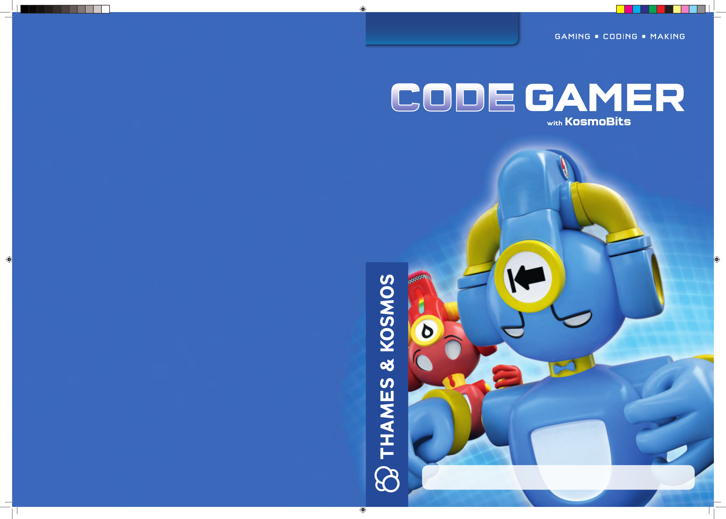
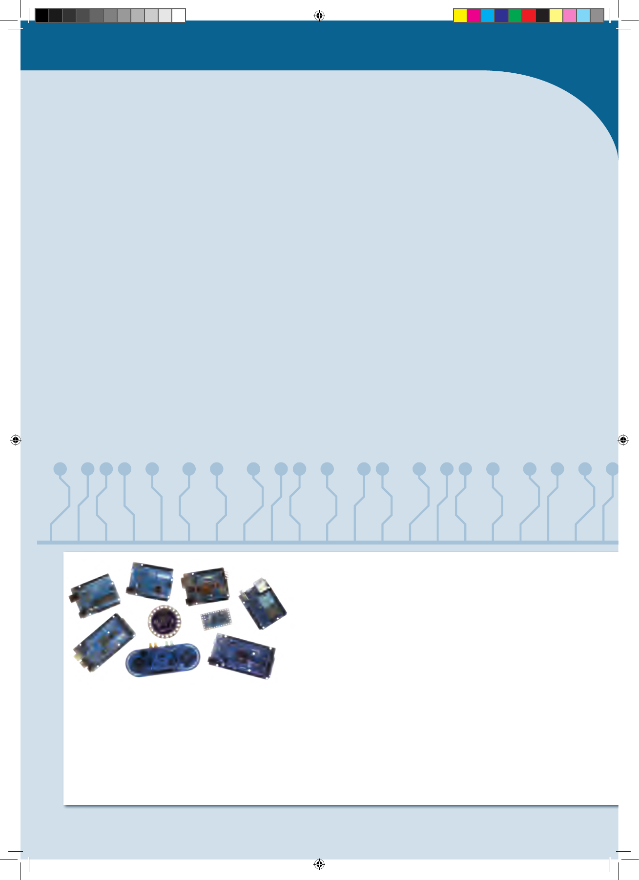
What’s inside your experiment kit:
Checklist: Find – Inspect – Check off
No. Description Quantity Item No.
1 KosmoDuino 1 717 982
2 Interaction board 1 717 981
3 Gamepad housing, top right 1 718 006
4 Gamepad housing, top left 1 718 007
5 Gamepad housing, bottom 1 718 005
6 Wheel with return spring 1 718 008
718 009
7 Buttons with rubber feet 1 718 010
718 011
8 Light sensor 1 717 985
9 Sound sensor 1 717 986
10 Temperature sensor 1 717 984
11 Motion sensor 1 717 983
12 Housing for sound sensor 1 718 000
718 004
13 Housing for light sensor 1 717 999
718 003
14 Housing for temperature sensor 1 717 997
718 001
No. Description Quantity Item No.
15 Housing for motion sensor 1 717 998
718 002
16 Breadboard 1 717 996
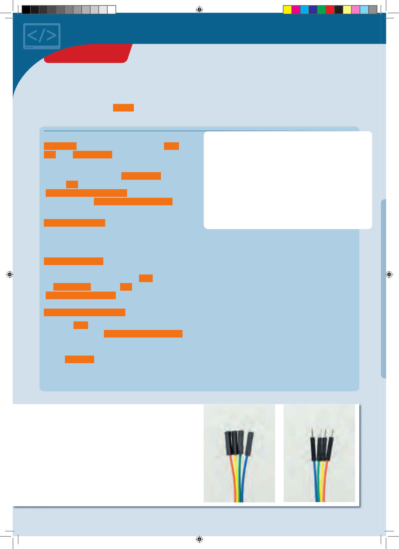
17 Jumper wires 10 717 990
male-female
18 Jumper wires 10 717 989
male-male
19 Resistors: 330 Ohm 5 717 991
20 LEDs: yellow 1 each 717 994
green 717 993
blue 717 995
red 717 992
21 Cable: USB to Micro-USB 1 717 988
22 Lithium polymer battery, 800 mAh 1 717 987
(not shown)
You will also need:
Smartphone or tablet with Android (4.3 or later) or iOS (Version
7 or later). The device must support Bluetooth 4 or higher. PC
with Internet access.
10
6
11
15
8
2
14
9
13
7
17
16
18 19
20
21 12
5
4
13
62 0141- 02-19 0716
GOOD TO KNOW! If you are missing any
parts, please contact Thames & Kosmos
customer service.
US: techsupport@thamesandkosmos.com
UK: techsupport@thamesandkosmos.co.uk
CodeGamer
› › › KIT CONTENTS
CodeGamer manual inside english.indd 1 7/19/16 12:31 PM
Safety Information .................................................. Inside front cover
Kit Contents ..............................................................................................
Table of Contents .....................................................................................
How to get started with CodeGamer ......................................................
Assembling the gamepad and sensors
The CodeGamer app
The World of the Microcontroller .............................................................
First steps ......................................................................................................
Installation of the Arduino Software
Project : Blink! ..................................................................................................
Upload a program to your KosmoDuino
Project : Off switch ........................................................................................
Project : On switch .........................................................................................
The Interaction Board .....................................................................................
Project : Colored light .....................................................................
Project : At the push of a button ....................................................
Project : A blinking die .....................................................................
Project : Serial monitor .....................................................................
The for loop ...........................................................................................
Sensors ....................................................................................................
Project : Thermometer ........................................................................
Project : Finger disco ...........................................................................
Project : Cheep! ...................................................................................
Project : Random sounds! ..................................................................
Project : Siren ......................................................................................
Project : Musical scale .....................................................................
Project : Sensor organ ......................................................................
Project : The serial plotter .............................................................
Project : Clap switch ......................................................................
Project : Drawer monitor ..............................................................
Project : Looking inside the fridge ..............................................
Project : Ghostly eyes ...................................................................
Common Error Messages ...............................................................................
Notes ...................................................................................................................
Publisher’s Information .......................................................Inside back cover
TIP !
You will find additional information on
the “Check It Out” pages (21, 59-61)
and “Knowledge Base” pages (24-25,
35, 41-42, and 58).
› › › TABLE OF CONTENTS
1000 1001
1101 101 00
100 10
1010
0
CodeGamer manual inside english.indd 2 7/19/16 12:31 PM
1
2
3
4
How to get started with CodeGamer
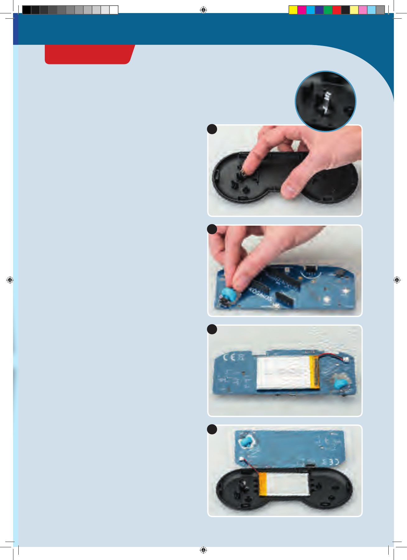
ASSEMBLING THE GAMEPAD
1. First of all, you will have to insert the little metal spring
into its correct location in the left area of the bottom part
of the housing. The spring will hold the wheel and ensure
that it always returns to its original position.
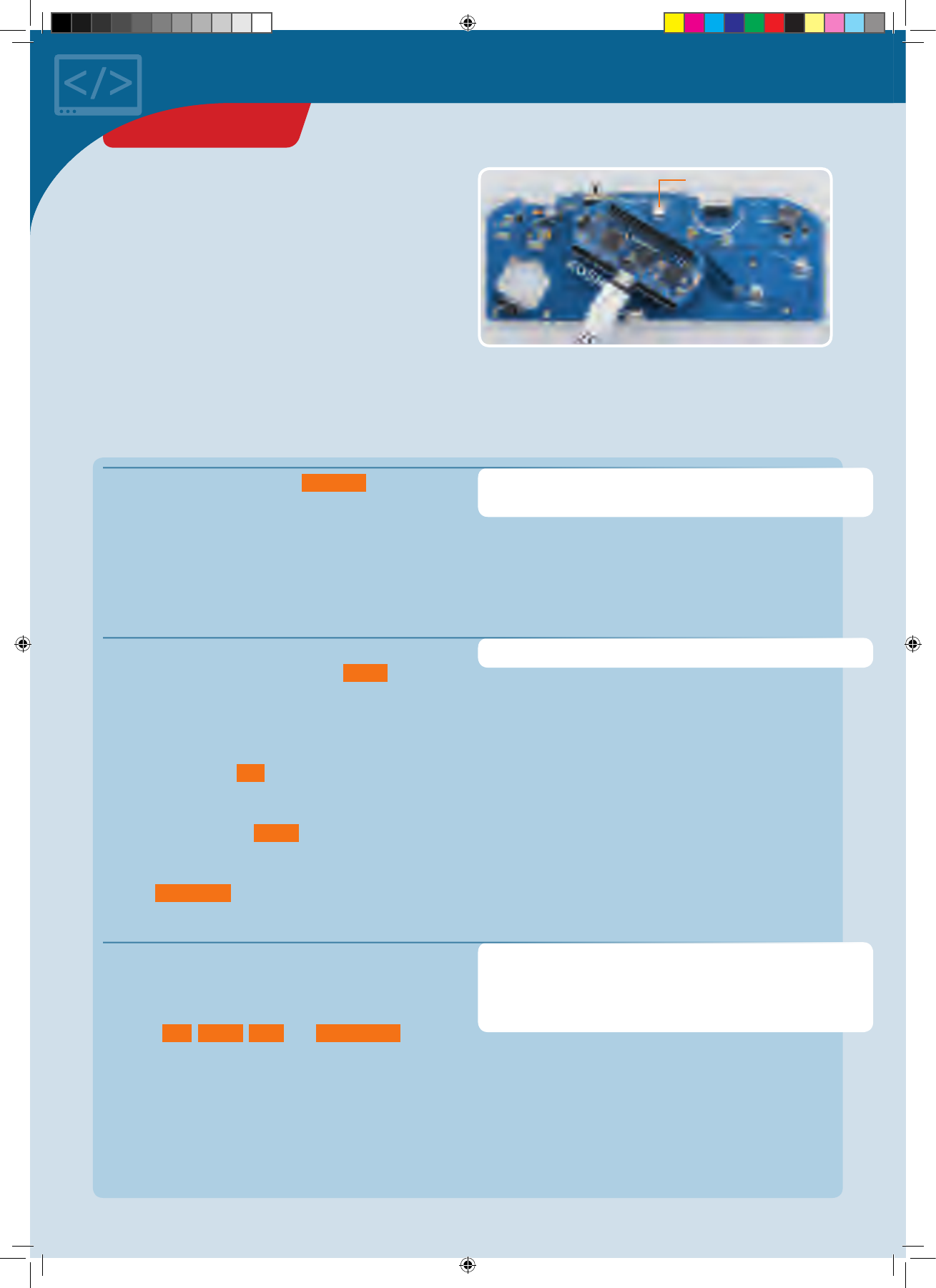
2. Next, you will have to insert the narrow axle of the
wheel into the rotation encoder hole. The rotation
encoder is attached to the interaction board and marked
there.
3. Connect the battery to the interaction board. The
attachment is on the bottom side. The battery’s plug is
shaped in such a way that it can only be connected in
the correct polarity direction. Do not force it!
4. Now place the battery in the lower housing of the
interaction board. Insert it so that it is securely mounted
and does not jiggle.
CodeGamer
GETTING STARTED
CodeGamer manual inside english.indd 3 7/19/16 12:31 PM
5
6
7
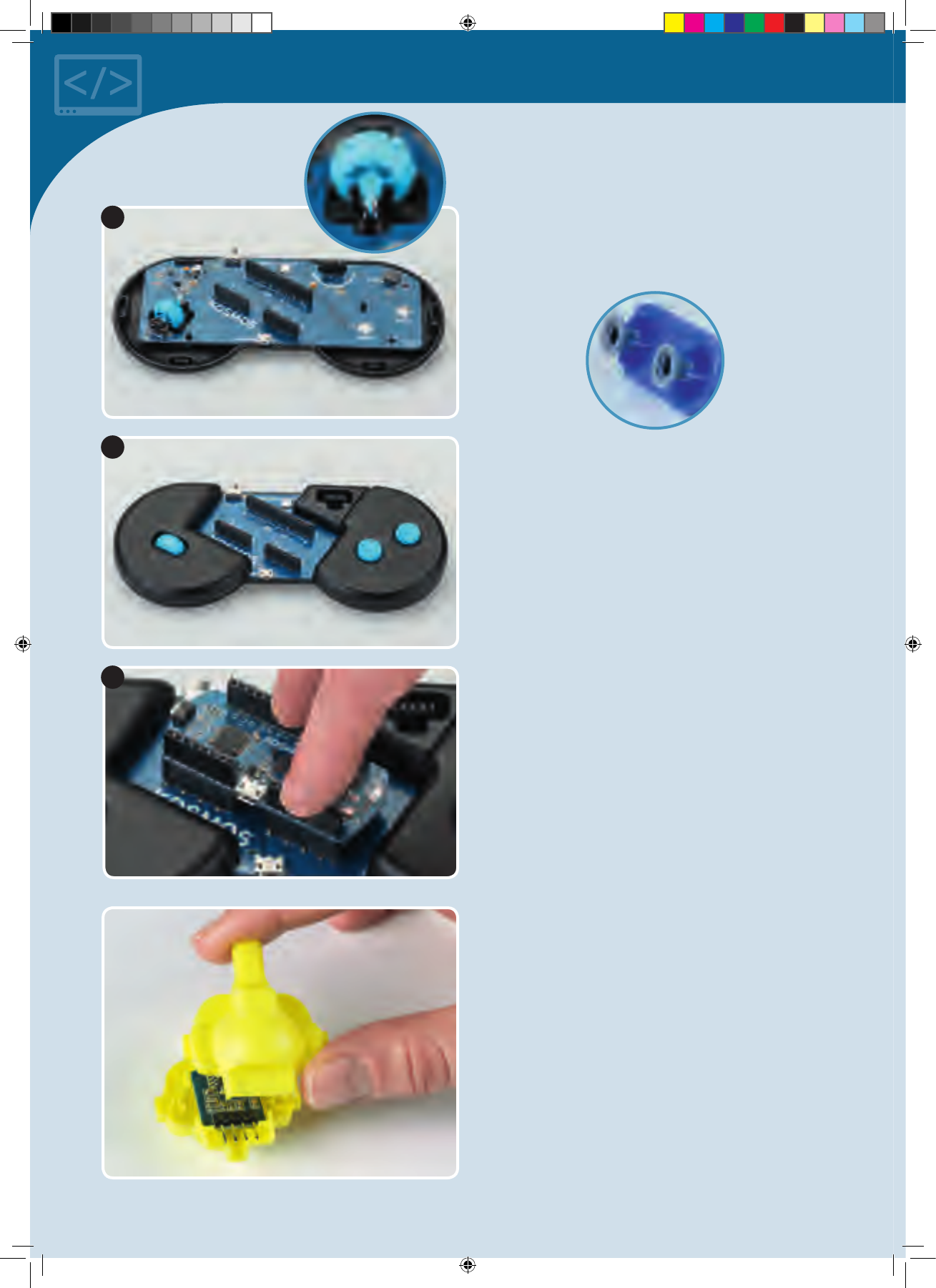
ASSEMBLING THE SENSORBOTS
1. Take one of the sensors and look for the housing with
the matching color (see page 1, “Kit Contents”). Insert
the sensor front side forward into the half of the housing
with the eyes printed on it. The sensors’ “feet” (the metal
pins) are always closer to the back side.
2. Now all you have to do is attach the rear of the housing
to the front part. To do that, just press the two parts
firmly together.
5. Now you can insert the interaction board into the
housing. Be sure that the wheel is mounted correctly in
the spring (see image in circle).
6. Attach the gray rubber feet onto the bottom of each
button. To do this, simply insert the thinner side of the
rubber foot into the recess on the bottom of the button.
Then, insert the button plate into the right upper
gamepad housing. Be sure that the buttons are
positioned correctly. You know that everything is
correctly placed when you feel an explicit trigger point
when the buttons are pushed. Then, attach the left
upper housing.
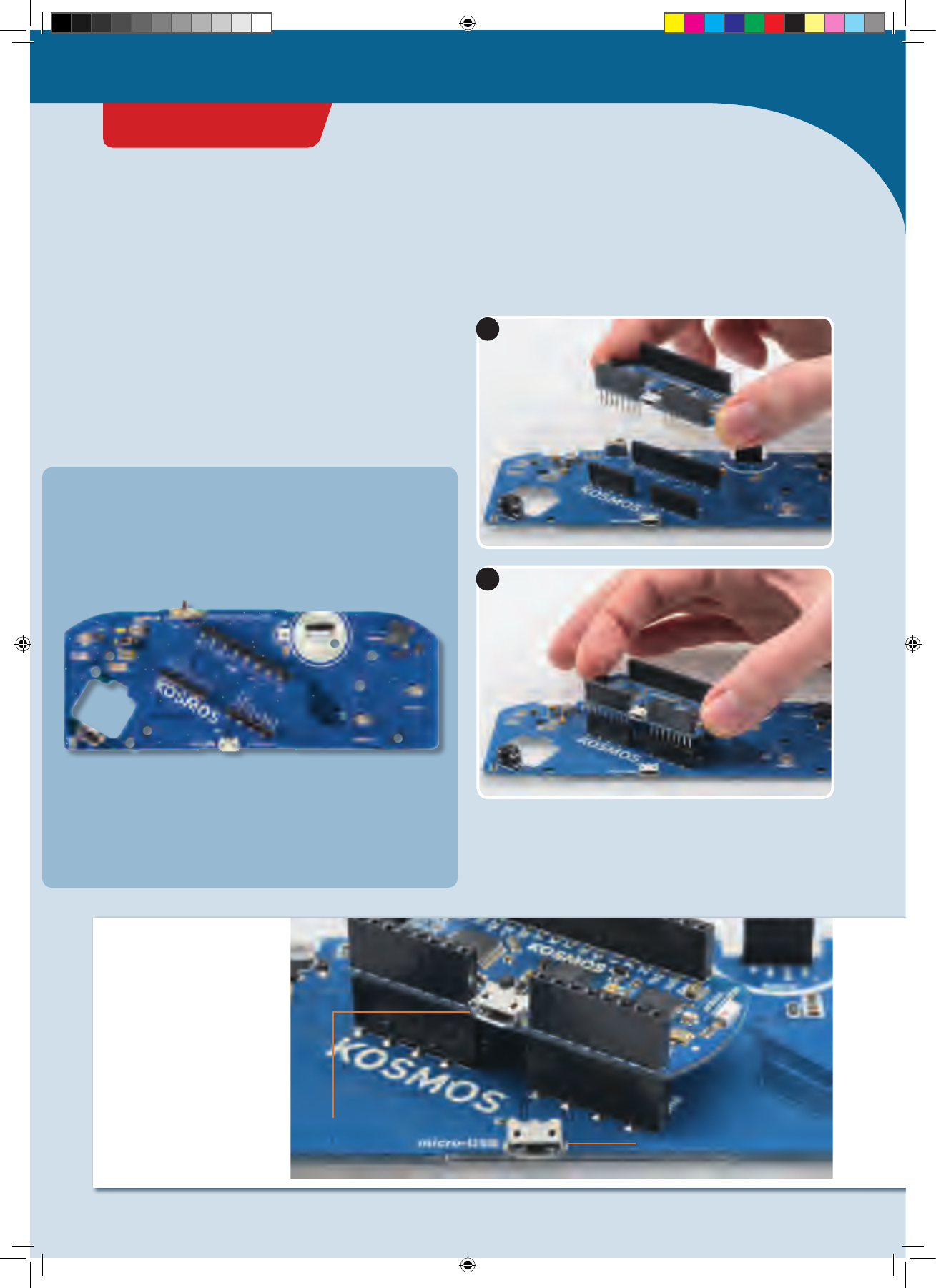
7. Your gamepad is now completed except for its “control
center,” the KosmoDuino. You can simply attach this to
the interaction board. Make sure that all the pins fit and
do not bend when you attach it. Press the KosmoDuino
far enough in that its “feet” (the metal pins) are no
longer visible.
CodeGamer manual inside english.indd 4 7/19/16 12:31 PM
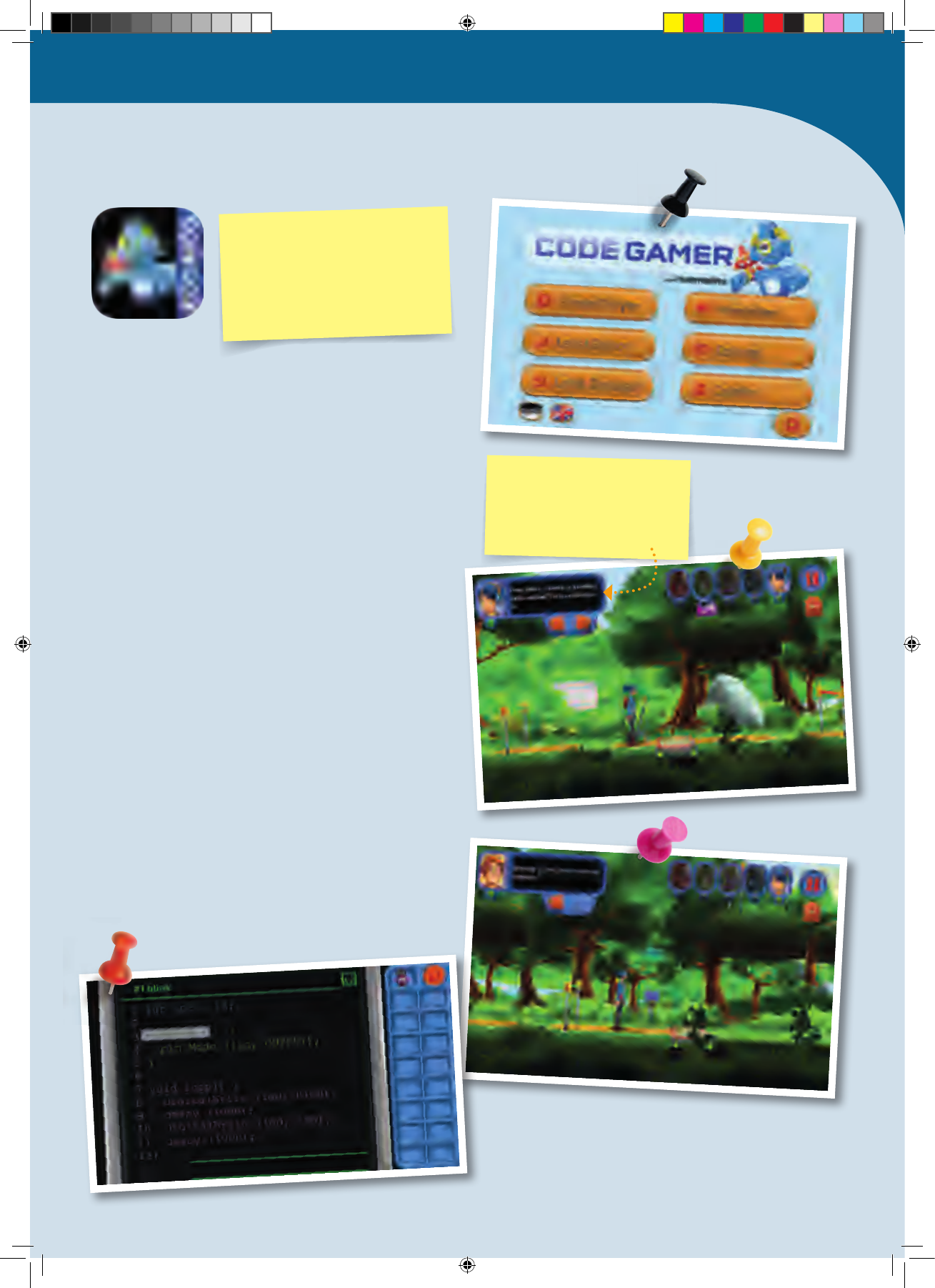
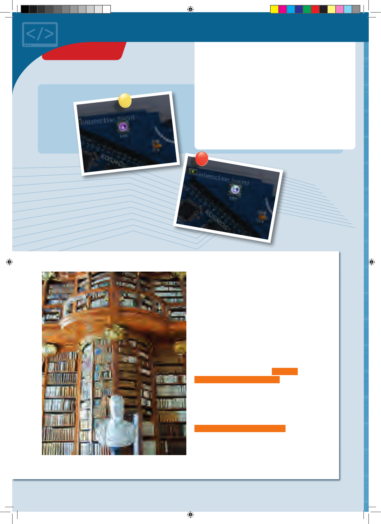
◀▲Various CodeGamer App screenshots
THE APP
To ease your entry into the world of programming, we
have developed an app to help you start building
experience in this area.
The core of the app is a video game in which you have to
solve little programming puzzles. But don’t be afraid — they
aren’t hard, and you will definitely be able to figure them
out. The key to solving the puzzles lies with the code
monsters that you will find at every level. Collect them all,
because you will need them at the computer terminals. The
computer terminals contain incomplete code. To fill in the
blanks, you will need to drag the correct code monster into
the matching blank spaces. To learn more about the
monsters, just tap once or twice on them in your inventory
— and they will tell you which blank space in the code they
will complete.
Use your gamepad to control the characters in the game.
To do this, you must have Bluetooth activated on your
tablet or smartphone. Start the app and switch on the
gamepad by sliding the switch at the upper edge to the
“ON” position. The connection will then be made
automatically in a few seconds. Once the connection is
active, the control elements (arrows and A and B buttons)
will disappear from the screen and you can control the
app with just the gamepad. If you switch off your
gamepad, the control elements will reappear. But the
game is not nearly as much fun without the gamepad!
CodeGamer
SYSTEM REQUIREMENTS:
KosmoBits supports devices with
Android 4.3 and iOS 7 operating
systems or later. The device has
to support Bluetooth 4 or higher.
Important! Take the time to
read the information, tips, and
hints presented in the
communication console here.
CodeGamer manual inside english.indd 5 7/19/16 12:31 PM
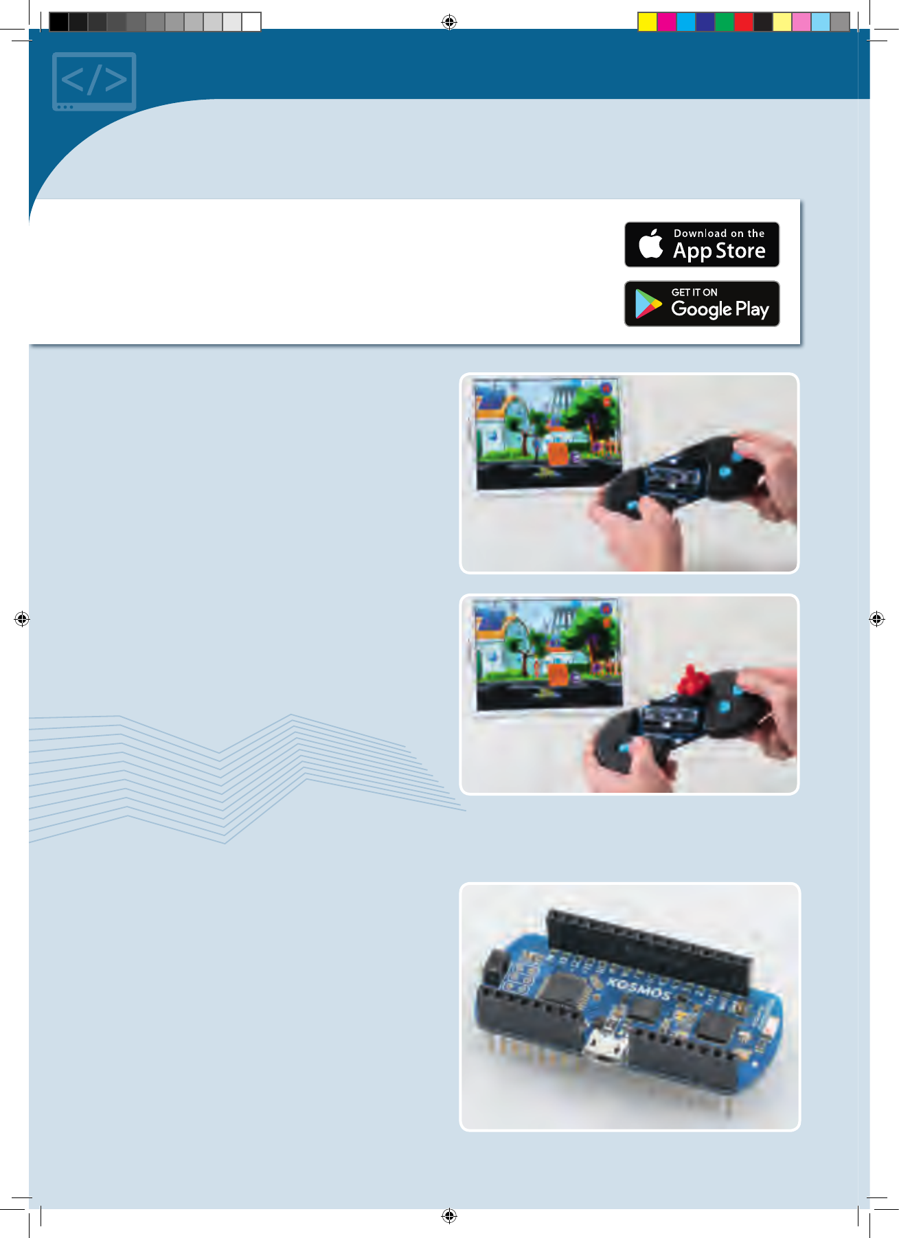
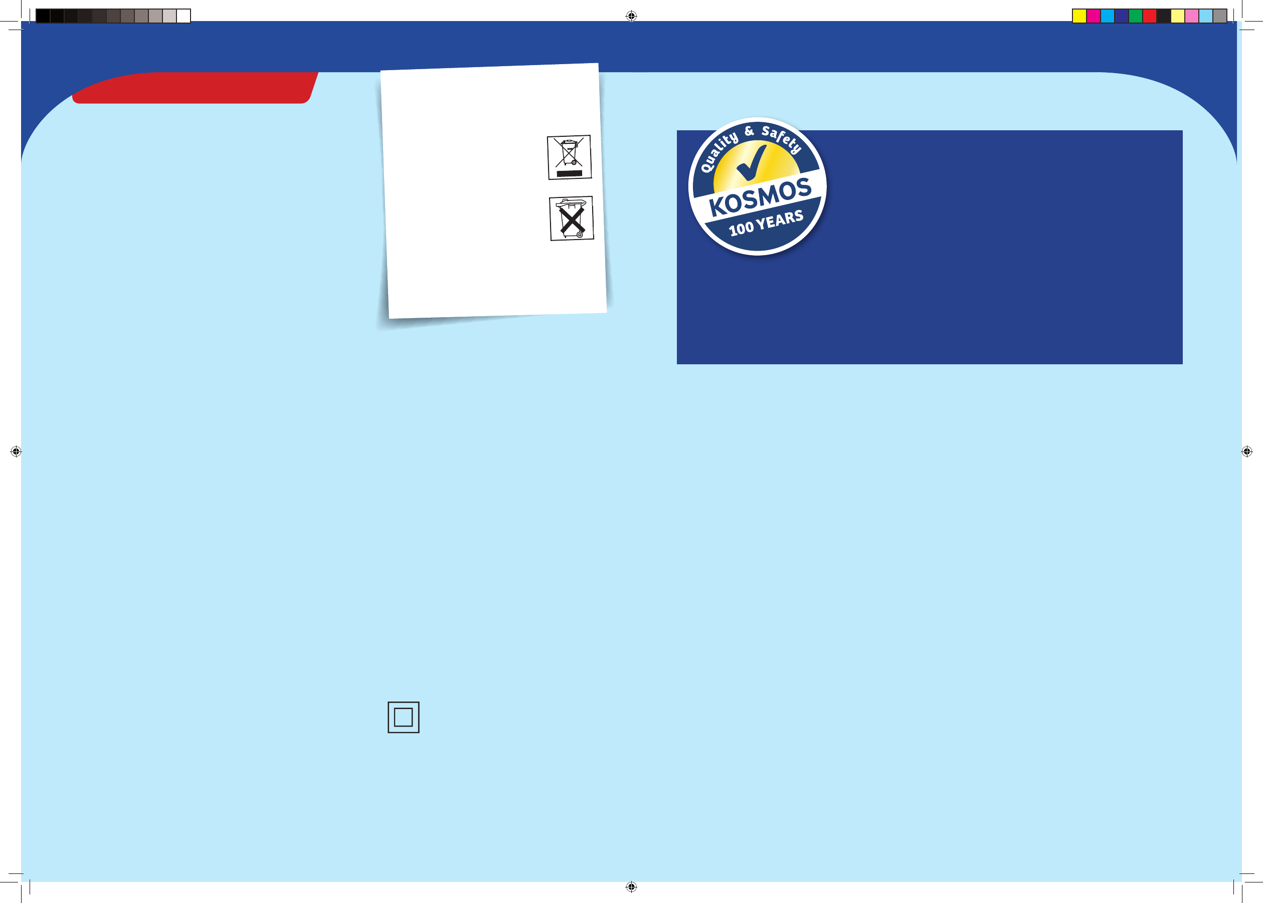
▲KosmoBits controller
!
HOW TO DOWNLOAD THE FREE APP:
To install your app, you will need access to Google Play or the Apple App Store. Ask
your parents or adult supervisor for help installing the app.
If your device runs on Android, open Google Play. Open the App Store with an iPhone or
iPad. Just enter the search term CodeGamer and install the app.
You will need your four sensorbots to play the game.
They are very handy for helping to clear obstacles out of
your way in the game. You can simply insert them into
your gamepad (see picture). As soon as you have inserted
a sensorbot, your game character will turn into one of the
four bots. Each one has its own special abilities. If you
have inserted the blue “Newton” bot, for example, you will
have to shake your gamepad vigorously back and forth to
activate its abilities. We will let you find out on your own
how to activate the special abilities of the other
sensorbots.
Play the game once through and take a look at the other
contents of the app in the main menu. You will find a lot
there about your experiment kit and the topic of
programming.
We hope you have a lot of fun experimenting with code!
The World of the
Microcontroller
Welcome to the world of the microcontroller! It looks
astonishingly similar to your own world. Or more
precisely: It looks exactly like your own! All around you,
there are countless microcontrollers going about their
work unnoticed. There’s hardly any electronic device that
works without a microcontroller
—
an electrical
toothbrush, the remote control for your TV, the controller
for your video gaming system, a digital thermometer, a
talking doll, a barking toy dog, the washing machine, the
smoke detector, the toaster, and so on …
CodeGamer manual inside english.indd 6 7/19/16 12:31 PM
!
WHAT DOES ARDUINO MEAN, ANYWAY?
In this instruction manual, you will come across the word
“Arduino” a lot. That is the name for a widely-used microcontroller
platform on which the KosmoDuino was based.
For a long time, microcontroller programming was only for
specialists. In 2005, the founders of the Arduino project took it
upon themselves to make the programming and use of simple
microcontrollers as easy as possible. That way, art students and
hobbyists who had never before had any experience with
programming would be able to use microcontrollers in their work.
Since then, a large community has formed around the Arduino
platform and lots of interesting projects have developed out of it.
You can copy a lot of them with your KosmoDuino, which is
compatible with an Arduino Uno board.
You can learn more about the Arduino project at www.arduino.cc.
BUT WHAT IS A
MICROCONTROLLER?
A microcontroller is a small (“micro”) computer. But it is
also fundamentally different from the computers that you
normally deal with: It has no keyboard, no mouse, and no
screen.
Instead, it has a lot of little feet, known as pins. A pin is
something like a connection between the microcontroller
and the outside world. Some of the pins have specified
functions. Most, however, are so-called GPIO pins. That’s
an abbreviation for General Purpose Input/Output. These
GPIO pins can be used for both inputs and outputs. And
that’s just what you need here.
. INPUT:
You can connect an input pin to a sensor, for example. This
will monitor the outside world and send information
about the surroundings, temperature, or brightness to the
processor via fluctuating levels of electrical voltage. In
your gamepad, an input pin is also activated when you
press a button.
. OUTPUT:
Depending on how it is programmed, the processor can
also respond to this information. For that, you will need
output pins to establish the connection to LEDs or the
sound module, which will then react to the level of the
transmitted electrical voltage by emitting various sounds
or colors.
Things really get exciting when you use several pins at the
same time. That way, the microcontroller can react to the
sensors all on its own — for example, by sounding an
alarm when it gets too hot.
The thing your microcontroller has in common with a
normal computer is the main processor that serves as the
brain of any computer. That’s the little black square at the
top left of your microcontroller. In the middle, there is a
small processor. This is what is responsible for the
communication between the microcontroller and the PC.
At the right is the Bluetooth chip, which enables wireless
connections with other devices.
CodeGamer
CodeGamer manual inside english.indd 7 7/19/16 12:31 PM

▲Download page on www.arduino.cc
Preparation
To program your KosmoDuino, you will need an ordinary PC
or laptop with the Arduino software installed on it. The
software is also called a programming environment, since it
includes a lot of tools that you will need for programming.
INSTALLATION OF THE ARDUINO
SOFTWARE
Download the Arduino software from https://www.
arduino.cc/en/main/software. On that page, you will find
various versions for the current operating systems. For
Windows operating systems, select “Windows Installer.”
After downloading, execute the downloaded file. Since the
Arduino software is constantly being revised, there are
always new versions. At the time that this manual was
printed, 1.6.6 was the current version, and the file was
called arduino-1.6.6-windows.exe. However, we
recommend working with version .., since this is the
version that was extensively tested by us. You will find
older versions on the “PREVIOUS RELEASES” page. After
starting the installer, follow the instructions to complete
the installation.
INSTALLATION OF THE KOSMOBITS
LIBRARIES AND SAMPLES
In a software library, you will find lots of useful and
reusable functions that will make programming easier for.
The ones we developed are called the KosmoBits libraries.
They also contain a lot of sample programs that you will
find in this manual. You must install these libraries.
The KosmoBits libraries can be downloaded by entering
http://thamesandkosmos.com/codegamer/kosmobits_
archive.zip link into your web browser. The file is called
kosmobits_archive.zip. This is a zip file that you will have
to unzip and move into the Arduino libraries folder.
On the next page, you will be asked for a contribution. The
Arduino project, which promotes the development of the
Arduino software, is largely financed by these kinds of
donations. You can also download the software for free
without making a donation by clicking on “Just
Download.”
Windows:
1. Open the explorer.
2. Go to the downloads folder.
3. Double-click the kosmobits_archive.zip file to open
it.
4. Select all the files and folders in the libraries folder
by simultaneously pressing the “Ctrl” and “A” keys.
5. Then press “Ctrl” and “C” to copy the selected files.
6. Go to the Documents ➜ Arduino ➜ libraries folder.
7. Now simultaneously press the “Ctrl” and “V” keys to
paste the files and folders into the libraries folder.
Mac:
1. Unzip the kosmobits_archive.zip file.
2. Drag the contents of the libraries folder into the
Documents ➜ Arduino ➜ libraries folder.
On either platform, you can alternatively try installing
the libraries through the Arduino application itself:
1. In the Arduino application, go to the Sketch menu and
choose Include Library ➜ Add .ZIP Library...
2. Navigate to the kosmobits_archive.zip file and click
Choose/Open.
THE KOSMOBITS CONTROLLER
With your KosmoBits controller, you are holding your very
own microcontroller in your hands. We named it
KosmoDuino because it is based on the Arduino
microcontroller. (KosmoBits is the name of the electronic
system in this kit.) You can do a lot with the KosmoDuino,
but first you have to learn how to program it. This manual
will explain how.
Okay! Now you can begin programming. You will just need
to open the Arduino application to get started.
Important! You must download and install the Arduino application from:
https://www.arduino.cc/en/main/software
and you must download and install the Kosmobits libraries and programs from:
http://thamesandkosmos.com/codegamer/kosmobits_archive.zip
CodeGamer manual inside english.indd 8 7/19/16 12:31 PM
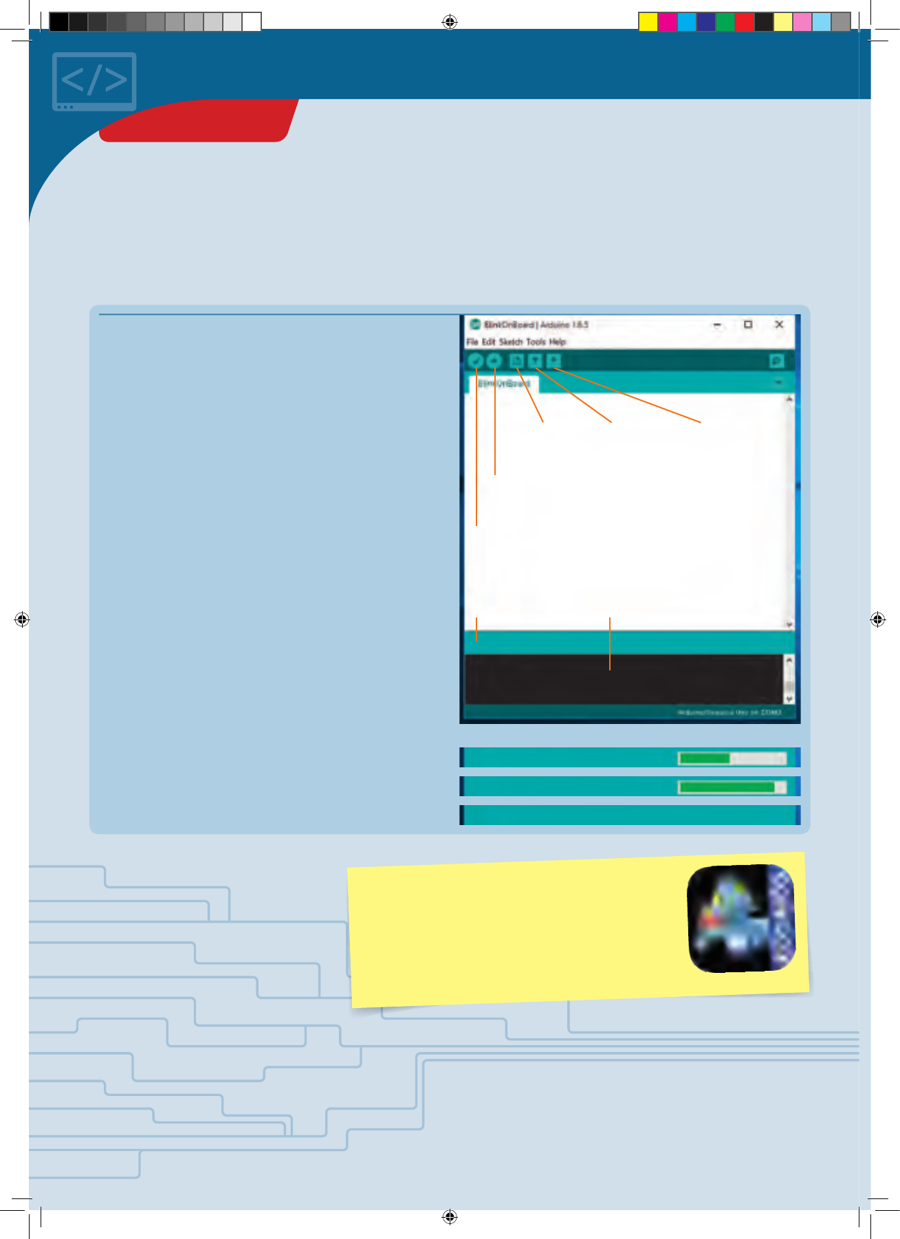
To write your first program, launch the Arduino
environment on your computer. A window will open into
which you can enter your program code. A few lines have
already been entered for you:
void setup() {
// put your setup code here, to run once:
}
void loop() {
// put your main code here, to run repeatedly:
}
int ledPin = 13;
void setup() {
pinMode(ledPin, OUTPUT);
}
void loop() {
digitalWrite(ledPin, HIGH);
delay(5 00);
digitalWrite(ledPin, LOW);
delay(5 00);
}
s e t u p ()
l o o p()
ARDUINO SWITCHED ON
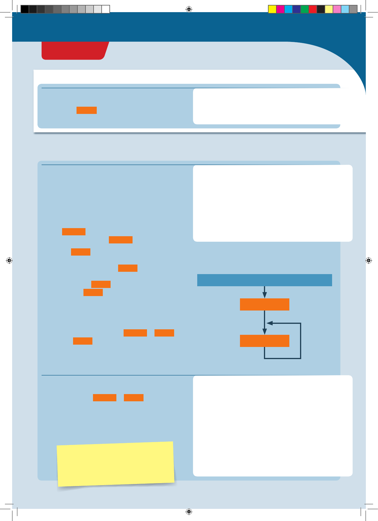
That is the basic skeleton for every Arduino program:
1. Your KosmoDuino starts by processing all instructions
in the s e t u p () function, i.e., all functions written in the
curly brackets following s e t u p () .
2. Then, the l o o p() function is invoked. That means that
your microcontroller executes all instructions written in
the curly brackets following l o o p() . Once the final
instruction has been processed, your controller once
again invokes the lo o p () function. In other words, the
instructions in l o o p() are invoked over and over in an
endless loop. That is why it’s called a loop function.
You can visualize this idea a little more clearly in a flow
diagram. The program always proceeds in the direction of
the arrows: from switching on, to s e t u p () , to l o o p() and
then back to lo o p () again and again.
You could upload this program right away to your
KosmoDuino if you wanted. But since there are no
instructions in either s e t u p () or l o o p() , the program
wouldn’t do anything.
So why not give your KosmoDuino something to do? Try
changing the program code like this:
▲Flow diagram
In the field of Arduino programming, the
term “sketch” is often used to refer to a
program. In this instruction manual, both
terms will be used.
This is where the explanation for the program code is
written. Portions taken from the code are always
highlighted in orange .
PROGRAM CODE EXPLAINED:
Here is where the program code is written
// Comments on the code are always in gray.
// This text is not a functional part of the
// code. It provides explanation and clarity.
Your first program: Blink!
</>
!
CodeGamer
PROJECT 1
CodeGamer manual inside english.indd 9 7/19/16 12:31 PM
</>
To upload a sketch to your KosmoDuino, proceed as
follows:
1. Connect the KosmoDuino to your computer with the USB
cable. You will not need the interaction board.
2. Save your program code if necessary. To do that, click
on the “save” symbol in the Arduino environment.
3. Make sure that the correct board is selected:
Tools ➜ Board ➜ “Arduino/Genuino Uno.”
4. Make sure that you have selected the correct port:
Tools ➜ Port ➜ e.g., “COM3” (Arduino/Genuino Uno).
5. Now click on the “upload” symbol in the Arduino
environment.
Don’t let yourself be intimidated by all the strange terms and brackets! We will go through the program step by step. You
will soon see that it isn’t hard to understand at all!
But before we can see what the program does, we have to upload it to
the KosmoDuino. Follow the instructions below to learn how to do this.
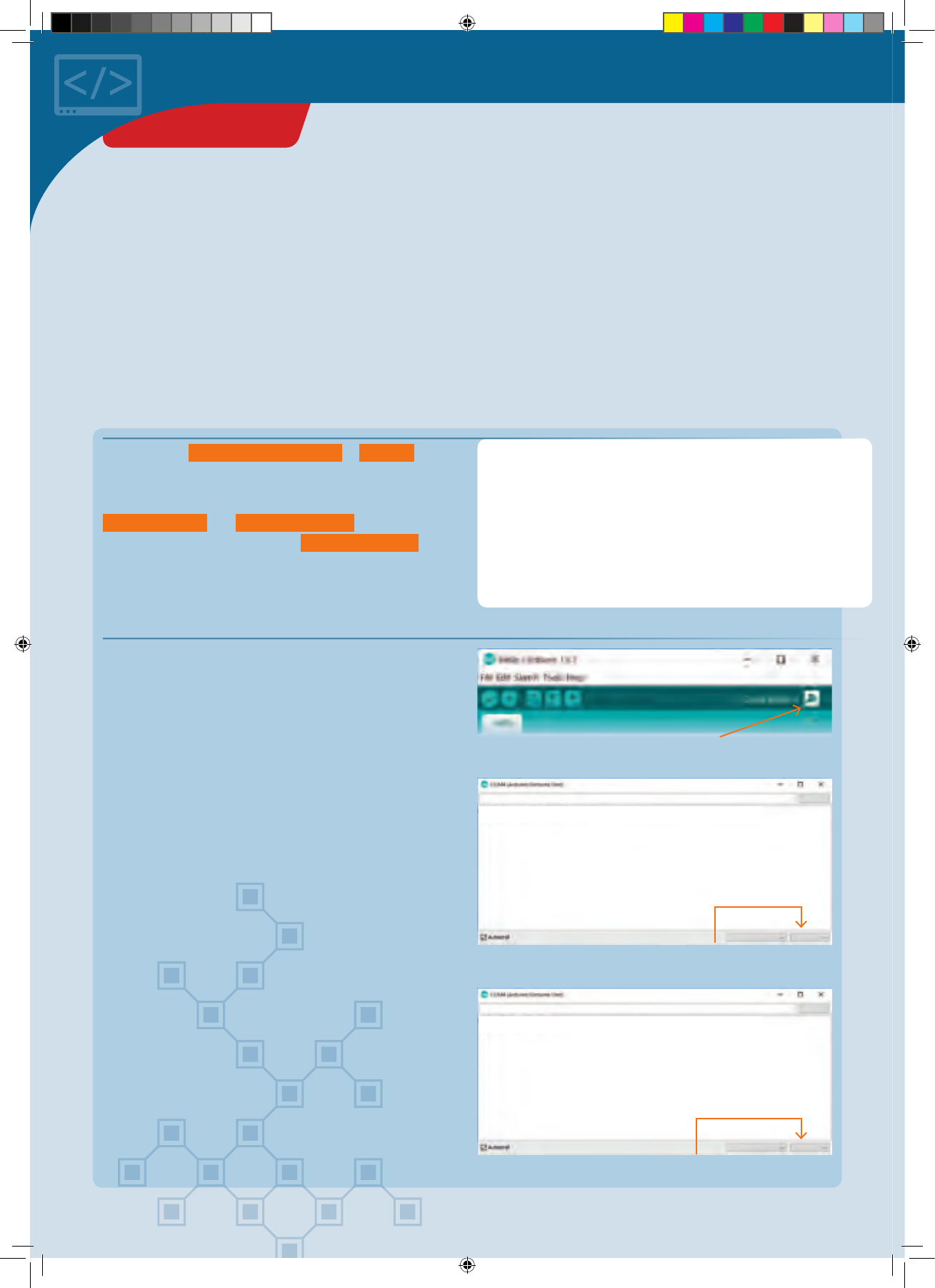
New Open
Upload
Save
Status line Window for further
explanations
Verify
If you did everything correctly, the following messages
should appear in sequence in the status line:
1. Compiling sketch …
2. Uploading …
3. Uploading completed.
Compiling sketch
…
Uploading
…
Uploading completed.
UPLOADING A PROGRAM TO KOSMODUINO
You can only ever upload one program at a time to
your KosmoDuino. If you want to play the KosmoBits
game with your gamepad, you will have to install the
KosmoBits_App.ino file. This file comes pre-installed
on your KosmoDuino when your kit is shipped.
PROJECT 1
CodeGamer manual inside english.indd 10 7/19/16 12:31 PM
!
ERROR MESSAGE?
If you see an error message, take a careful look at the
program text you entered. Is it possible that you wrote
something incorrectly? The place where an error leads to
problems in the program text is marked in red in the
Arduino environment (see illustration). In any case, you
should try looking for the actual error first. Even just tiny
typos will lead to error messages! If you cannot find an
error, then take a look at the yellow box below. There,
under the “Opening the sample programs” heading, you
will find an explanation of how you can use the example
programs described in this manual without having to type
them into the computer from scratch.
Typo: “pinnMode” instead of “pinMode!” The
location of the error is highlighted in red. ▶
BlinkOnBoard.ino: In function 'void setup()':
BlinkOnBoard:11: error: 'pinnMode' was not declared in this scope
'pinnMode' was not declared in this scope
'pinnMode' was not declared in this scope Copy error messages
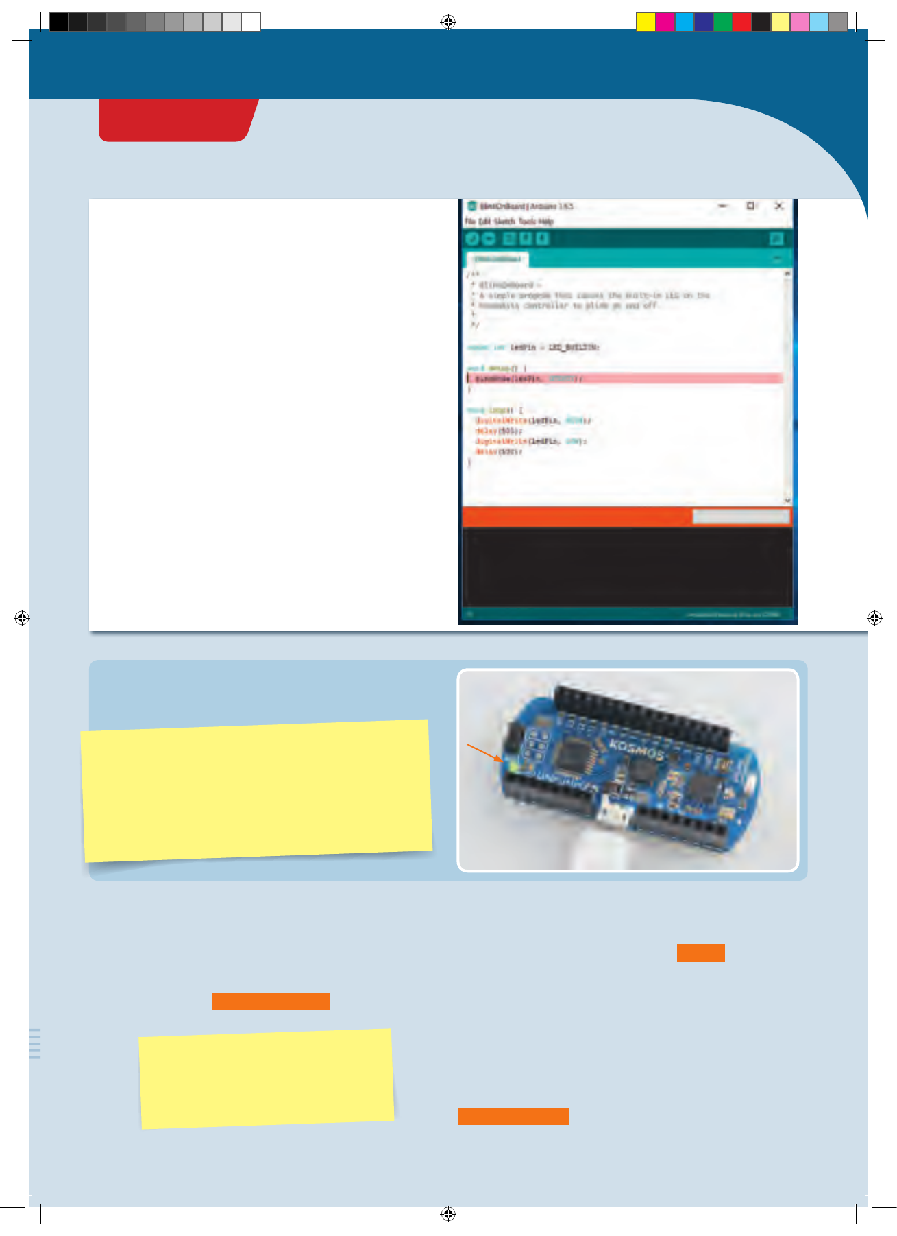
Did everything work? Great! If so, you will now see a little
green LED — the “onboard LED” — blinking on and off on
the KosmoDuino.
Opening the sample programs
All sample programs can be opened directly, so you can
bypass typing them in by hand. You will find them in the
Arduino environment in this menu:
File ➜ Examples ➜ KosmoBits
EXPLANATION
Now it’s time to really understand the program. Let’s take
a closer look at it.
The first line reads: int ledPin = 13;
In the Arduino programming language,
instructions must be closed with a
semicolon (“;”).
This defines a variable with the name ledPin . Variables
are important components of any program. You can save
any value you like in a variable — numbers, letters, or
entire words. Each variable has a name. The name allows
you to invoke the saved value whenever you like.
If you want to save a value in a variable, use the equals
sign (“=”). The variable goes on the left side of the equals
sign, while the value goes on the right. For example,
int ledPin = 13 means that the value 13 is saved in the
PROJECT 1
CodeGamer
CodeGamer manual inside english.indd 11 7/19/16 12:31 PM
void setup() {
pinMode(ledPin, OUTPUT);
}void loop() {
digitalWrite(ledPin, HIGH);
delay(5 00);
digitalWrite(ledPin, LOW);
delay(5 00);
}
Here, a function is defined. The function is called
s e t u p ()
.
When a function is invoked in the program code, all the
instructions contained in it are carried out step by step.
Those are all the instructions written between the curly
brackets. So you can think of a function as a small
sub-program.
The function s e t u p () , by the way, is a special function. It
is always the first thing that is automatically invoked
whenever you start your KosmoDuino.
But what does the s e t u p () function actually do? It
invokes another function: pi n M o d e() . This is the function
that allows you to specify the operating mode in which a
pin is going to work. In this case, the ledPin (pin number
13) is to work as OUTPUT , or the output pin.
An output pin works like a switch that you turn on or off
as determined by the program. You will learn about the
other possible operating modes in later projects.
If the instructions in s e t u p () have been processed by
your KosmoDuino, the next thing to be invoked is the
l o o p() function. Let’s take a look at what this function
contains:
!
FUNCTIONS
Functions allow you to divide up your programs into smaller blocks. That can help you keep a clear overview, and it
promotes order in the program. Also, you can pack frequently used sequences of instructions into a single function.
Instead of repeating the same text in the program code every time, you can simply invoke the corresponding function.
Just as with the definition of a variable, to define a function you have to start with an example. In this case, let’s take
void .
This is the so-called return type. A function, in other words, can end by returning a value to the program that invoked it.
In this case, the return type is void , meaning “empty.” In other words, this function returns no value at all! An example
of a value that might be returned is the temperature measured by a sensor.
Important: Always give your functions a name that conveys what the function does. That will help you understand the
program when you’re reading it.
variable ledPin . The way you say it is: “The value 13 is
assigned to the variable ledPin .”
Wherever you want to use the number 13 in your program,
you can now write “ledPin” instead of “13.”
BUT WHAT DOES int MEAN?
In the Arduino programming language, a variable cannot
take just any value you like. The values must be of a
certain type that has to be determined. In this case, the
type is int . That means that the variable can take a so-
called integer value.
For your KosmoDuino, those values are the whole numbers
from -32768 to 32767.
PROJECT 1
CodeGamer manual inside english.indd 12 7/19/16 12:31 PM
What happens when l o o p () is invoked? The first
instruction in l o o p() is:
digitalWrite(ledPin, HIGH);
You can use digitalWrite() to control whether voltage
is applied to an output pin or not. When issuing this
request, there are two things that you will have to
communicate to the digitalWrite() function:
1. Which pin is intended?
2. Should the voltage at the pin be switch on ( HIGH ) or
off ( LOW )?
In this case, voltage is switched on at pin number 13
(ledPin ), and the LED lights up!
If you want to switch on another pin, let’s say pin
number 9, you would write digitalWrite(9, HIGH); .
The next instruction is:
del a y(500); .
You can use the d el a y() instruction to delay the program
sequence for a specific period of time — in other words, to
make it wait. The amount of time is determined by the
number that you assign with the request, in this case 500 .
The time is indicated in milliseconds (thousandths of a
second). 500 milliseconds is half a second. So the program
waits and does nothing for half a second.
Then we have the instruction
digitalWrite(ledPin, LOW); .
You can probably understand this one without any help.
Right — the LED is switched off again!
Then the KosmoDuino waits another half a second:
del a y(500); .
And then?
Then it starts all over again from the beginning! l o o p() is
a special function in the Arduino programming. It repeats
endlessly! All commands in lo o p() are carried out over
and over in an endless loop. This is known as the main
loop. This makes lo o p () the most important function in
any KosmoBits program. It controls what the KosmoDuino
actually does, while s e t u p () handles the required
preliminary steps.
You have already seen what happens when the main loop
is repeated: The LED is switched on and off, over and over,
in regular intervals of half a second. In other words — the
LED blinks.
!
TYPES A few common type specifiers and their meanings
TYPE MEANING VALUES
int Whole numbers or HIGH / LOW (on/off) -32,768 to 32,767
long Whole numbers, large -2,147,483,648 to 2,147,483,647
float
Floating decimal numbers: numbers with a
decimal point
e.g., 1.5; 3.141; 2.678
double Like float but with twice the precision e.g., 3.141964; 21.45873
char Individual letters e.g., a; A; c; C
const Unchangeable value Can take any values
PROJECT 1
CodeGamer
CodeGamer manual inside english.indd 13 7/19/16 12:31 PM
Off switch
In your first “blink” sketch, you learned how to use a
program to make an LED blink on your KosmoDuino. To do
that, you used a pin on your controller as an output pin to
make the LED switch on and off.
But you can also use a pin as an input pin. In this case, the
pin is not turning voltage on or off. Instead, the program
can tell you whether or not an electrical voltage is
supplied to the pin.
You can then use that to turn the LED on and off with a
simple switch.
YOU WILL NEED
›
KosmoDuino
›
male-male jumper wires (see explanation on p. )
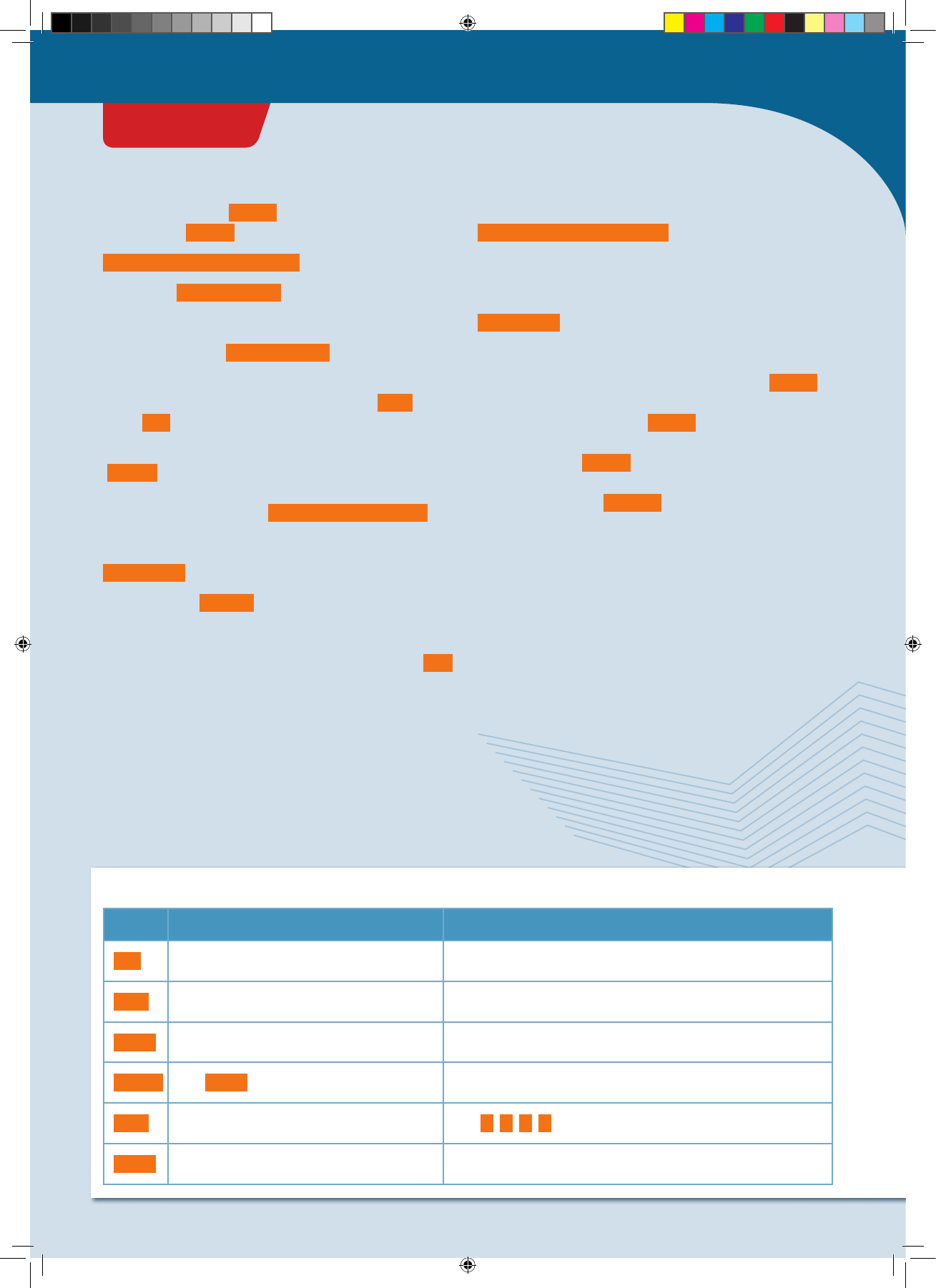
PREPARATION
Attach one jumper wire to pin 9 and the other to one of the
GND pins. GND stands for ground or grounding. These pins
have no actual function beyond conveying current.
int ledPin = 13;
int switchPin = 9;
int switchValue = HIGH;
void setup() {
pinMode(ledPin, OUTPUT);
pinMode(switchPin, INPUT_PULLUP);
}
void loop() {
switchValue = digitalRead(switchPin);
digitalWrite(ledPin, switchValue);
delay(5 0);
}
THE PLAN
Upload the sketch to your KosmoDuino as described on
page 10. After uploading, the LED will light up. If you then
bring the two free jumper wire contacts together and
make them touch, the LED will stop shining.
THE PROGRAM
So what does the program do?
int ledPin = 13;
int switchPin = 9;
int switchValue = HIGH;
You will first have to define three variables:
• ledPin for the pin to which the LED is connected.
• switchPin should be assigned the value 9, because you
will be connecting your “switch” to pin 9.
• switchValue will start by getting the value HIGH .
Later on, you will “read out” pin 9 and save the readout
value in switchValue .
PROJECT 2
Warning! Not suitable for children under 8 years.
There is a risk of hot surfaces of components on the
PCB (printed circuit board) when different polarities
are incorrectly short-circuited or the capacitor is
subject to fault conditions.
CodeGamer manual inside english.indd 14 7/19/16 12:31 PM
void setup() {
pinMode(ledPin, OUTPUT);
pinMode(switchPin, INPUT_PULLUP);
}
void loop() {
switchValue = digitalRead(switchPin);
digitalWrite(ledPin, switchValue);
delay(5 0);
}
</>
This is almost the same as in your first program. The
ledPin is operated as an output pin ( OUTPUT ). Pin 9
(switchPin ), on the other hand, is operated as an input
pin. So in the pi n M o d e() instruction for switchPin ,
instead of the value OUTPUT , you will use INPUT_PULLUP .
First, use digitalRead(switchPin) to read out the
current state of pin 9. If the pin is electrically connected to
a “GND” pin, it yields the value LOW . That means that
there is no voltage supplied. Otherwise, it yields the value
HIGH . Save this value in the switchValue .
Then, write this value into the LED pin. So if pin 9 is
connected to the GND pin, it switches off the LED.
Otherwise, the LED will be switched on.
Finally, d elay(50) will make you wait briefly before the
entire sequence repeats.
On switch
YOU WILL NEED
›
KosmoDuino
› male-male jumper wires
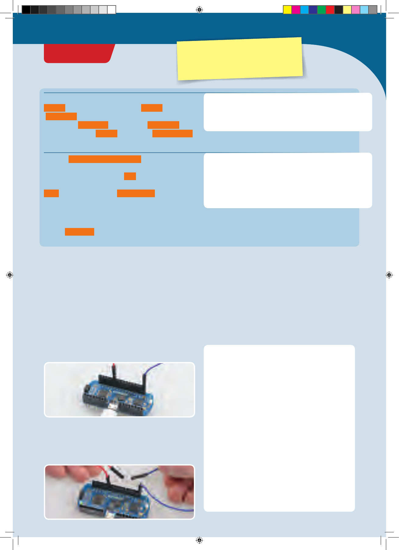
PREPARATION
Connect one jumper wire to pin 9, and the other to one of
the GND pins. int ledPin = 13;
int switchPin = 9;
int switchValue = HIGH;
void setup() {
pinMode(ledPin, OUTPUT);
pinMode(switchPin, INPUT_PULLUP);
}
void loop() {
switchValue = digitalRead(switchPin);
if(switchValue == LOW) {
digitalWrite(ledPin, HIGH);
} else {
digitalWrite(ledPin, LOW);
}
delay(5 0);
}
THE PROGRAM
Upload the sketch to your KosmoDuino as described on
page 10. This time, after uploading, the LED will remain
dark. It only lights up when you touch the two free jumper
wire contacts together.
THE PLAN
In the previous project, you learned how to switch off an
LED with the help of a simple switch. But what do you do if
you want it to work in reverse — in other words, to have
the LED only come on if the contact is closed? Just change
the program!
PROJECT 3
CodeGamer
Warning! Not suitable for children under 8 years.
There is a risk of hot surfaces of components on the
PCB (printed circuit board) when different polarities
are incorrectly short-circuited or the capacitor is
subject to fault conditions.
CodeGamer manual inside english.indd 15 7/19/16 12:31 PM
EXPLANATION
Let’s just take a look at the
l o o p()
function, because that’s the only
place where anything was changed relative to the “off switch” program.
void loop() {
switchValue = digitalRead(switchPin);
if(switchValue == LOW) {
digitalWrite(ledPin, HIGH);
} else {
digitalWrite(ledPin, LOW);
}
delay(5 0);
}
Just as with the “off switch,” you start by reading out the
switchPin and saving the current value, i.e., HIGH or
LOW in the switchValue variable.
But you do not want to write the read value into the LED
pin — just the opposite: When switchValue has the
value of LOW , you want to switch on the LED
(digitalWrite(ledPin, HIGH) ); otherwise, you want to
switch off the LED ( digitalWrite(ledPin, LOW) ).
In the program text, you express that with
if(...){...} els e {...} . Note the “if” and “else.” You
guessed it — this lets you use the program to respond to
different conditions.
The condition to which you are responding here is
switchValue == LOW . You can understand that as a
question: “Is the switch value equal to LOW?” You can
evaluate the answer to that with the if() instruction: If
the switchValue is equal to LOW
(if(switchValue == LOW) ), the program code in the first
pair of curly brackets is carried out:
digitalWrite(ledPin, HIGH) . The LED is switched on.
Otherwise ( else ) the part in the second pair of curly
brackets is carried out: digitalWrite(ledPin, LOW) . The
LED is switched off.
Finally, d elay(50) will make you wait briefly before the
entire sequence repeats.
</>
!
JUMPER WIRES
Jumper wires serve as an easy way to connect electronic
components to each other. In this experiment kit, you will
find two different types: male-male and male-female.
They really are called that! “Male-male” means that there
is a wire on both ends. While “male-female,” on the other
hand, there is a wire on one end and a socket on the other.
Jumper wires are sometimes also called patch cables.
»Female End« »Male End«
PROJECT 3
CodeGamer manual inside english.indd 16 7/19/16 12:31 PM
The Interaction Board
OK, we admit it. Making a little LED light up is not very
exciting. Still, it helped to give you a quick introduction to
programming your KosmoDuino.
To help you learn how to do more exciting things with
your microcontroller as quickly as possible, we have
developed the interaction board. You may have gotten to
know it a little already while playing the CodeGamer
video game. It has several very practical components that
will come in handy for lots of projects:
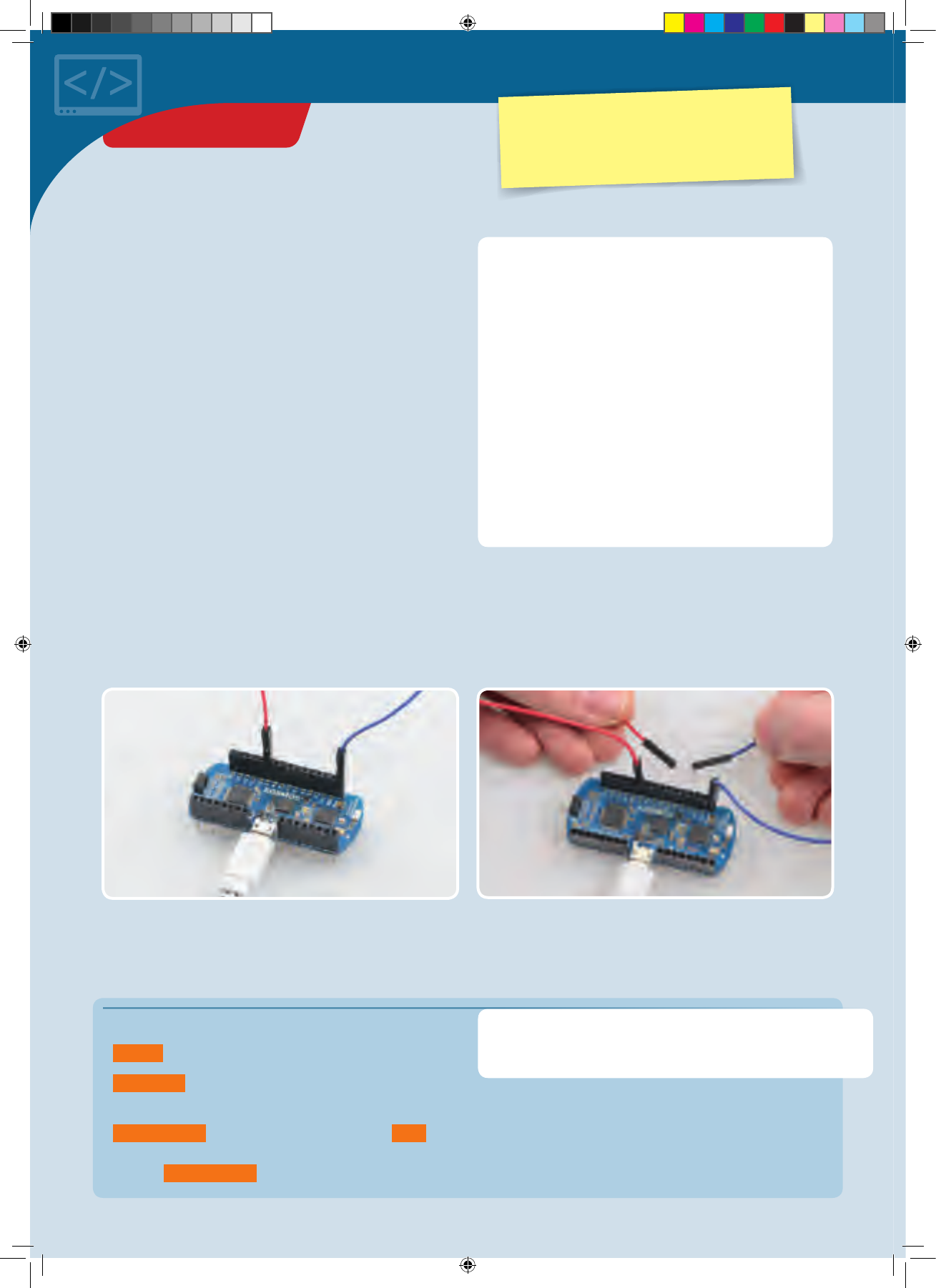
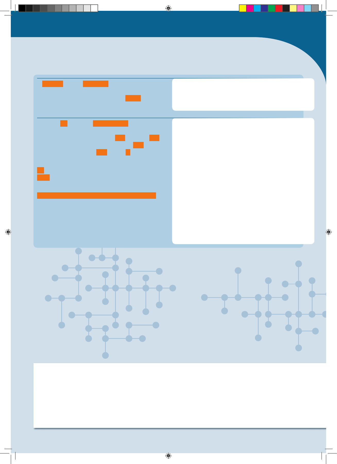
To work with the interaction board, you will first have to
insert your KosmoDuino into the board’s pin socket (see
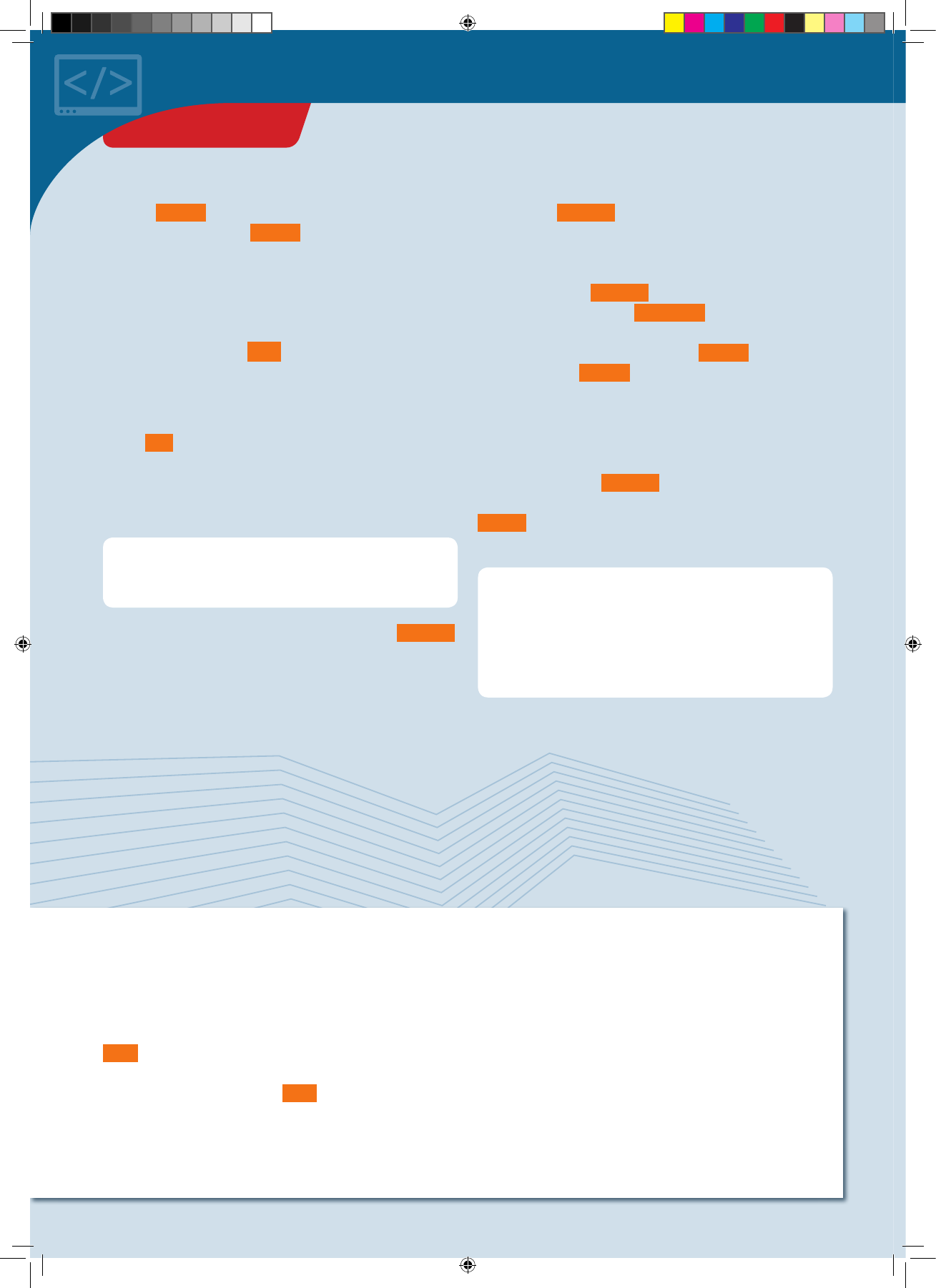
illustration).
!
NOTE!
To upload a program to the
microcontroller, you will
insert the USB cable into
the USB port on the
KosmoDuino. The USB
terminal on the interaction
board is only for charging
the battery.
1
2
Upload
program Charge battery
• Two buttons (“button 1” and “button 2”)
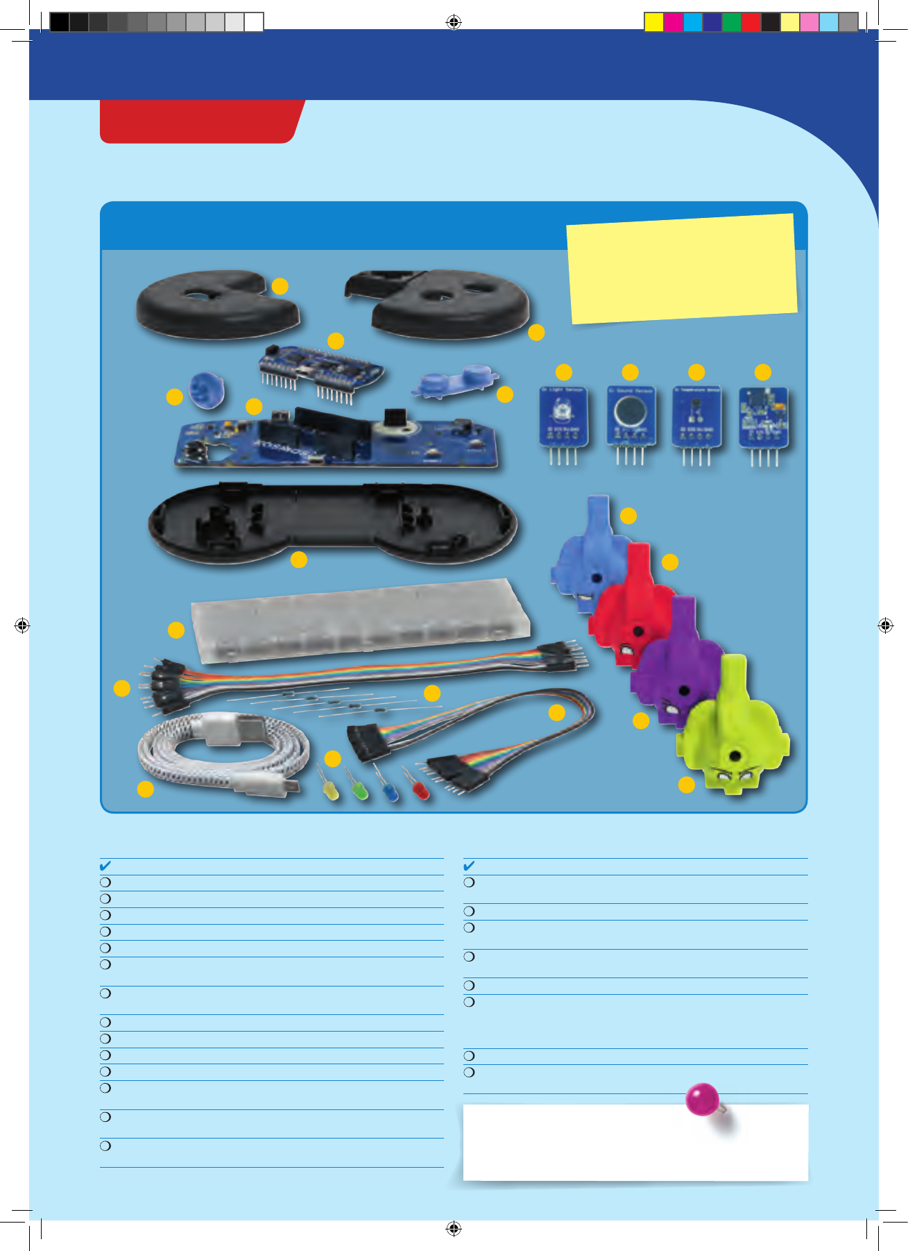
• A multicolored LED (“NeoPixel”)
• A rotating wheel (“rotary encoder”)
• A speaker (“buzzer”)
And most important:
• A socket for connecting the KosmoBits sensors
(temperature, motion, brightness, loudness)
• A battery so that you can also use your
KosmoDuino when it isn’t attached to a computer.
Then you’ll be ready to start! In the following projects,
you will start by exploring the interaction board’s
capabilities, and then move on to the more complex
projects.
CodeGamer
INTERACTION BOARD
CodeGamer manual inside english.indd 17 7/19/16 12:31 PM
Colored light
YOU WILL NEED
› KosmoDuino in the interaction board
THE PLAN
On the interaction board, you will find a multicolored LED
called a NeoPixel. It’s a kind of LED that lets you decide
what color and brightness level you want it to have. This
Up to now, you have only learned about variables that act
as containers for numerical values. The pixel variable
that you are defining here is a little different: Instead of
numbers, it serves as a container for an object of the
KosmoBits_Pixel type. That sounds more confusing than it
really is. It just means that objects can be more than
simple values such as int .
More specifically, rather than just having one value, they
can bring their own functions with them. These are also
known as methods. Your pixel , for example, is an object
that you can use to control the NeoPixel on your
interaction board. For that purpose, it has a method by the
name of setColor() , that you can use to adjust the color
and brightness of the NeoPixel. Next, in the main loop, you
will learn how this works.
To adjust the color and brightness of your NeoPixel, you
will need four number values — one for the brightness
and three for the primary colors red, green, and blue.
These values will be saved in the corresponding
variables red , green , blue , and brightness .
The various colors will be produced by mixing these three
basic colors. You will be setting the corresponding
number value to determine how strongly each of the
colors in this mixture will be represented. You can use
values from 0 to 255. 0 means that the corresponding
color will not light up at all. With a value of 255, the
color will shine with the highest possible brightness.
KosmoBits_Pixel pixel;
#include <Adafruit_NeoPixel.h>
#include <KosmoBits_Pixel.h>
int red = 0;
int green = 0;
int blue = 0;
int brightness = 0;
Here’s something new to you. The
#include
instruction
will let you include code from other programs in your
program. In this case, you will be including content from the
“Adafruit_NeoPixel.h” and “KosmoBits_Pixel.h” files
.
You will always have to insert these two lines at the
beginning of your program when you want to use the
NeoPixel!
Multicolored NeoPixel LED
THE PROGRAM
little project will show you how it works, and how to get
your NeoPixel to shine in all sort of colors
</>
PROJECT 4
CodeGamer manual inside english.indd 18 7/19/16 12:31 PM
void setup() {
// There is nothing to do here.
}
void loop() {
// 50 is a good brightness value.
// The highest brightness level is 255.
// It can be a bit blinding though!
brightness = 50;
// r e d
red = 255;
green = 0;
blue = 0;
pixel.setColor(red, green, blue, brightness);
delay(5 00);
// g r e e n
red = 0;
green = 255;
blue = 0;
pixel.setColor(red, green, blue, brightness);
delay(5 00);
// bl u e
red = 0;
green = 0;
blue = 255;
pixel.setColor(red, green, blue, brightness);
delay(5 00);
// p u r ple
red = 255;
green = 0;
blue = 255;
pixel.setColor(red, green, blue, brightness);
delay(5 00);
// t ur q u o ise
red = 0;
green = 255;
blue = 255;
pixel.setColor(red, green, blue, brightness);
delay(5 00);
// y ell o w
red = 255;
green = 255;
blue = 0;
pixel.setColor(red, green, blue, brightness);
delay(5 00);
</>
In s e t u p () there will be nothing for you to do this time,
since the program that you will be linking with the
#include instruction will already be handling it for you.
In the main loop, the first thing to do is set the brightness:
brightness = 50; . The highest level of brightness is set
with a value of 255; with 0, the NeoPixel remains dark.
Then the various colors are produced one after the other.
To do that, you will be assigning the red , green and
blue variables different values.
The line
pixel.setColor(red, green, blue, brightness); is
the decisive factor for each color. First of all, it tells the
NeoPixel that it is supposed to display a new color! In
these instructions, setColor() is a so-called method of
the pixel object. To invoke a method of an object, the
method’s name is attached to the name of the object
separated by a period.
With d el ay(500); you will make your KosmoDuino wait
half a second before adjusting the net color.
The NeoPixel
shines in
various colors ▶
CodeGamer
CodeGamer manual inside english.indd 19 7/19/16 12:32 PM
// w hite
red = 255;
green = 255;
blue = 255;
pixel.setColor(red, green, blue, brightness);
delay(5 00);
}
</>
!
SOFTWARE LIBRARIES
To avoid having to reinvent the wheel with every
program, there are software libraries. These are not
book collections. Instead, they contain reusable
program functions and definitions. There are some
libraries that provide mathematical functions, while
there are others to make it easy to use certain types of
hardware such as sensors or NeoPixels. To be able to use
the tools that this kind of library can make available to
you, you have to include the corresponding library in
your own program.
You do this with the help of the #include instruction:
#include <KosmoBits_Pixel.h> includes the
KosmoBits_Pixel library, for example. Some libraries,
however, use functions from other libraries. They have to
be additionally included, such as in the KosmoBits_Pixel
library. More specifically, in order to work they require
the Adafruit_NeoPixel library, which is linked via
#include <Adafruit_NeoPixel.h> .
▲Another type of library
PROJECT 4
CodeGamer manual inside english.indd 20 7/19/16 12:32 PM
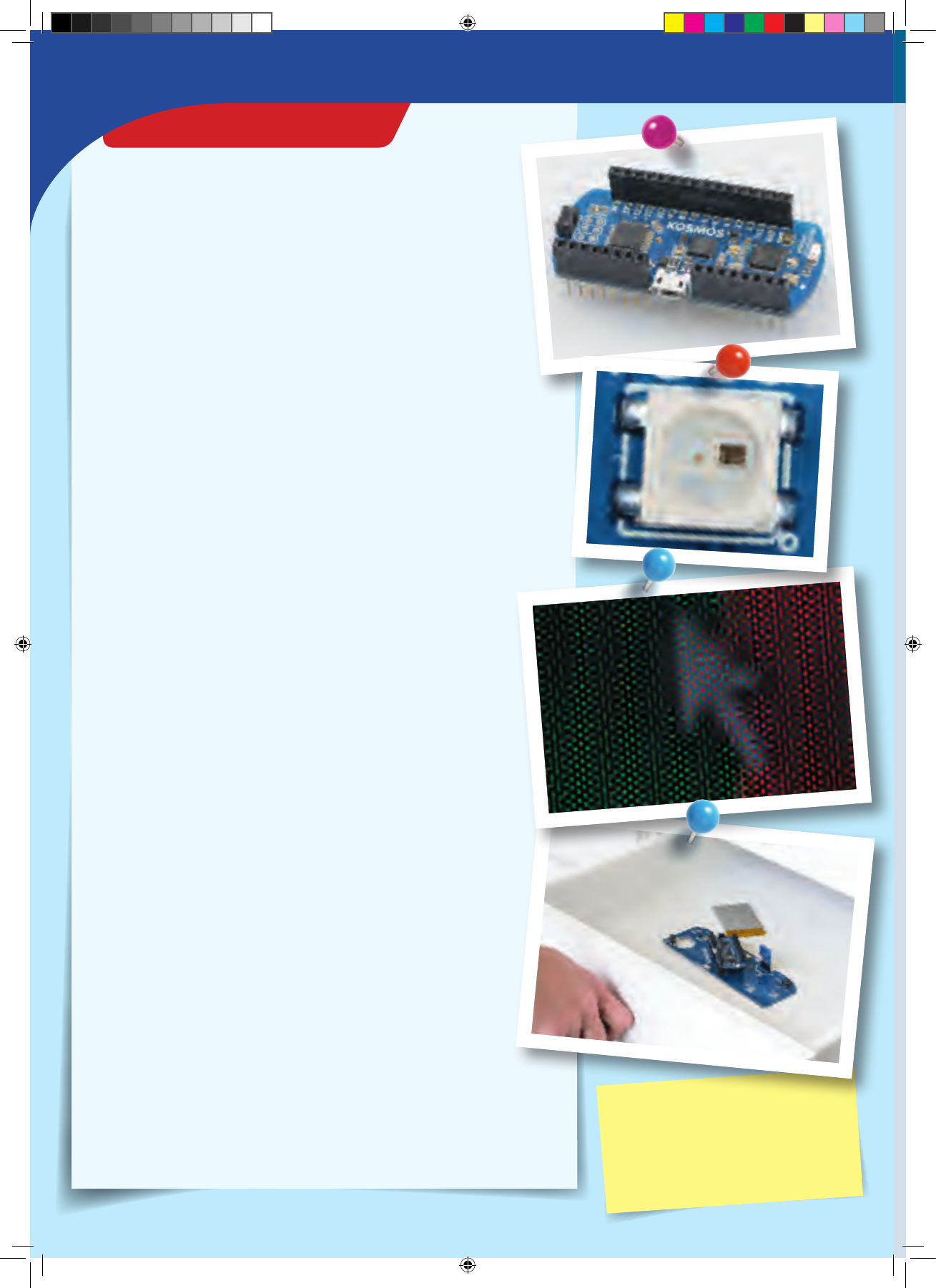
Additive
Color Mixing
What you see as white light is actually a mixture of different lights of
various colors. Which colors? Take a look at a rainbow and you will see them all. A rainbow is
created when the sun’s light is split up into its component colors by raindrops in the air.
This process can also work in reverse when you mix light of various colors together, resulting in a
different color. Any color monitor or screen works by this principle — whether on your TV, your
computer, your smartphone or your tablet. In all these devices, each individual picture element
(“pixel”) consists of three single-colored picture elements of red, green, and blue. Because they are
packed so tightly together, you cannot perceive the individual dots from a normal distance. You can
only see the individual dots of color if you get really close, or use a magnifying lens.
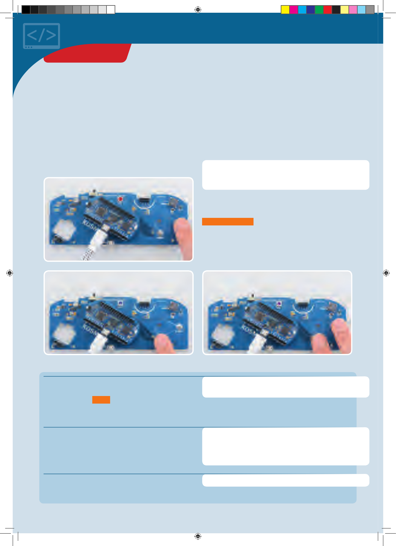
If you look carefully at the NeoPixel on the interaction board, you will be able to see three different
regions (as long as it isn’t shining). Each region can only produce one single color — red, green, or
blue. With the help of the
s e t C ol o r()
method, you can tell the NeoPixel how brightly you want
each of the different regions to shine.
Experiment with mixing together other colors by
varying the individual color values. The picture next to the
table below will serve as a reference for anticipating which
mixtures will produce which colors. Enter your findings into
the following table:
Color name Red Value Green Value Blue Value
Red 255 0 0
Green 0255 0
Blue 0 0 255
CHECK IT OUT
CodeGamer
Enlarged photograph of a screen, reveling the
individual dots of color.
In this close-up, you can easily see the three
individual LEDs of the NeoPixel. ▶
▲You can see
the component
colors of
sunlight in a
rainbow.
CodeGamer manual inside english.indd 21 7/19/16 12:32 PM
At the push of a button
In this project, you will learn how to use the buttons on the
interaction board to make the NeoPixel light up in
different colors.
YOU WILL NEED
› KosmoDuino in the interaction board
THE PLAN #include <Adafruit_NeoPixel.h>
#include <KosmoBits_Pixel.h>
#include <KosmoBits_Pins.h>
Here, you are defining two constants for the pins to which
the two interaction board buttons are connected. These
are abbreviated as const . This keyword communicates to
the program that an object or a variable cannot be
changed.
As in the previous program, you are saving the various
color values and the brightness in corresponding
variables that you define here.
To be able to control the NeoPixel on the interaction
board, you once again need a KosmoBits_Pixel object.
You are defining that here.
const int button1 = KOSMOBITS_BUTTON_1_PIN;
const int button2 = KOSMOBITS_BUTTON_2_PIN;
int red = 0;
int green = 0;
int blue = 0;
const int brightness = 50;
KosmoBits_Pixel pixel;
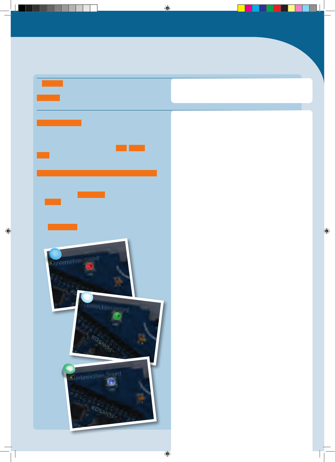
First, we want the NeoPixel to stay dark. If you press
button 1, the NeoPixel will glow red, while if you press
button 2 it will glow blue. If you press both at the same
time, it glows purple.
THE PROGRAM
You learned in the last project how to link to libraries and
code from other files in a program. The new library here is
KosmoBits_Pins.h
. This defines names for the various
KosmoDuino pins used by the interaction board. We will
take a closer look at the KosmoBits libraries a little later
on in this manual.
▲Finger pushes right button — NeoPixel glows red
▲Finger pushes left button — NeoPixel glows blue ▲Two fingers push both buttons simultaneously — NeoPixel glows purple
PROJECT 5
CodeGamer manual inside english.indd 22 7/19/16 12:32 PM
</>
In
s e t u p ()
, you use
pi n M o d e()
to set the operating
mode for the button pins. Since the buttons are connected
to the pins via a resistor, you will use the
INPUT
operating type.
In the first
if
instruction
digitalRead()
is used to read
out the pin to which button 1 is connected. When the
button is pressed, it yields the value
LOW
: The value
255
,
i.e., the largest possible value, is assigned to
red
.
If the button is not pressed,
red
is set to
0
.
The entire sequence is repeated for button 2 in the second
if
instruction. The only difference is that the value for
blue
is given.
Finally,
pixel.setColor(red, green, blue, brightness);
sets the new color value for the NeoPixel.
At the end of the main loop, you make the controller wait
another 50 milliseconds.
void setup() {
pinMode(button1, INPUT);
pinMode(button2, INPUT);
}
void loop() {
if (digitalRead(button1) == LOW) {
red = 255;
} else {
red = 0;
}
if (digitalRead(button2) == LOW) {
blue = 255;
} else {
blue = 0;
}
pixel.setColor(red, green, blue, brightness);
delay(5 0);
}
!
WHAT ACTUALLY HAPPENS WHEN YOU UPLOAD SOMETHING?
When you upload a program to your KosmoDuino, actually, a whole lot of things happen. The microcontroller does not
really understand the program as you have written it. It simply doesn’t speak the programming language. That’s why
the program first has to be translated into machine language. That is something handled by a so-called compiler.
The programming language that you use, in other words, is just an intermediate language that is not only easy for you to
understand and write, but most important of all, is one that the compiler can easily translate into machine language.
CodeGamer
CodeGamer manual inside english.indd 23 7/19/16 12:32 PM
Only under one condition:
The “if” instruction
You have already used the
if
instruction in the
program code. Now it’s time to take a closer look. By
using the
if
instruction, you can require that
portions of your program will be carried out only
if a certain condition is fulfilled:
// Simple if instruction
if (Condition) {
/
/ The following is only carried out
/
/ if the condition is fulfilled.
Instruction 1;
Instruction 2;
...
}
OPERATOR MEANING EXAMPLE
true
== equal to a == b when a is equal to b
<less than a < b when a is less than b
> greater than a > b when a is greater than b
!= unequal a != b when a is unequal to b
<= less than or equal to a <= b when a is less than or equal to b
>= greater than or equal to a >= b when a is greater than or equal to b
!
ATTENTION!
A common and not always easy-to-find error in an
if
statement is instead of the double equal sign to use a
single equal sign. For example, instead of
if (a == b)
the incorrect statement would be
if (a = b)
.
In the case of this
if
statement the value of
a
is
assigned the value
b
. If that value is greater than zero
(
true
), the block of text in the curly brackets is
executed.
The parts of the program in the curly brackets will
only be carried out if the condition is fulfilled.
Otherwise, the entire block in the curly brackets will
simply be skipped.
The condition must return a truth value either
true
or
false
. Usually, two numerical values are
compared. In addition, there are relational operators
that will probably be familiar to you from math class:
if
INSTRUCTION 1
INSTRUCTION 2
Truth values are also known as
Boolean data types, abbreviated as
bool .
These can only take the values true
or false.
KNOWLEDGE BASE
CodeGamer manual inside english.indd 24 7/19/16 12:32 PM
You can also extend an
if
instruction with an
else
statement. The
else
statement is carried out if and
only if the condition is not fulfilled.
// if instruction with else statement
if (Condition) {
/
/ The following is only carried out
/
/ if the condition is fulfilled.
Instruction 1;
Instruction 22;
...
} else {
/
/ This block is carried out if
/
/ the condition is not fulfilled.
Instruction 3;
Instruction 4;
}
Finally, you can build in the additional block
else if
to check another condition if the first one is not
fulfilled.
// if instruction with else block
if (Condition 1) {
/
/ The following is only carried out
/
/ if the condition is fulfilled.
Instruction 1;
Instruction 2;
...
} else if (Condition 2){
/
/ This block is carried out if
/
/ the condition is not fulfilled.
Instruction 3;
Instruction 4;
} else {
/
/ This block is carried out if
/
/ none of the previously checked
/
/ conditions are fulfilled.
Instruction 5;
...
}
You can also omit the closing
else
statement. In
addition, you can line up as many
else if
statements in a row as you like.
CodeGamer
CodeGamer manual inside english.indd 25 7/19/16 12:32 PM
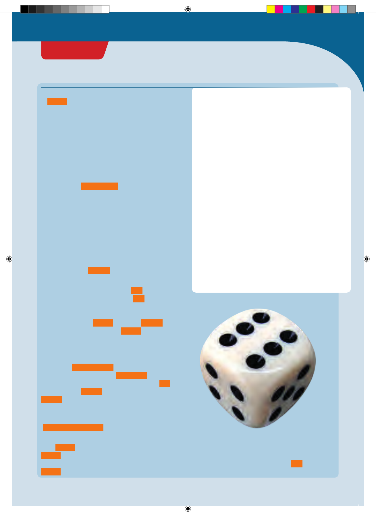
A blinking die
With this project, you will be turning your KosmoDuino
into a simple die. At the push of a button, it will generate a
random number from 1 to 6 and signal the result by
blinking the NeoPixel.
YOU WILL NEED
› KosmoDuino in the interaction board
#include <KosmoBits_Pins.h>
#include <Adafruit_NeoPixel.h>
#include <KosmoBits_Pixel.h>
KosmoBits_Pixel pixel;
const int buttonPin = KOSMOBITS_BUTTON_1_PIN;
const int blinkDuration = 500; // Milli s e c o n d s
const int blinkPause = 250; // M illi s e c o n d s
const int brightness = 50;
In s e t u p () , you prepare your controller for the upcoming
tasks in the usual manner: Use
pinMode(buttonPin, INPUT) to set the pin connected to
button 1 as the input pin.
Later, you will be generating a random number. This will
be handled by a random generator, which will need as
random a value as possible to start with. To get that, read
out pin 12 with analogRead(12) . Since nothing is
connected there, any values that you get will be random.
You will learn more about the analogRead() function a
little later. Then r a n d o m S e e d(...) delivers the read value
to the random generator itself as a starting value.
Finally, pixel.setColor(0, 0, 255, brightness);
makes the NeoPixel glow blue.
void setup() {
pinMode(buttonPin, INPUT);
randomSeed(analogRead(12)); // Starting value
// for random generator
pixel.setColor(0, 0, 255, brightness); // Bl u e
// signals operational readiness
}
void loop() {
if (digitalRead(buttonPin) == LOW) {
r oll();
}
}
You start by including the familiar libraries and add a
KosmoBits_Pixel to address the NeoPixel on the
interaction board.
Then, you add a few constants to make the code legible.
THE PLAN:
• If the controller is ready, the NeoPixel will glow blue.
• If you press button 1, the NeoPixel will begin to blink
green in accordance with the die result, i.e., once if the
rolled result was one, twice if it was two, etc.
• After a brief pause, the NeoPixel will return to blue. That
means that it’s ready to roll again.
In the main
l o o p()
, you read out the
buttonPin
with
digitalRead()
. When it is pushed, the result is
LOW
. With
the help of the
if
instruction the
r oll()
function is
invoked, which calculates and outputs the result of the die
roll. Otherwise,
l o o p()
does nothing.
</>
THE PROGRAM
This is a shortened version of the notation that you
learned in Project 4. The numbers in the brackets control
the RGB value (red/green/blue).
PROJECT 6
CodeGamer manual inside english.indd 26 7/19/16 12:32 PM
loop on pages 30/31
</>
Here’s where you define your own function by the name
of
r oll()
. It will calculate and then output a random
number in the range of 1 to 6. Let’s go through it step by
step:
First (1), you turn off the NeoPixel light and wait briefly.
You know the corresponding commands by now.
Now we come to the actual roll. Since your KosmoDuino
cannot literally roll dice, you have to get the result by
some other means: You query a random number
generator.
You do that with
random(1, 7)
(2). That lets you ask the
random generator for a randomly selected number. The
first parameter, 1 in this case, indicates that the smallest
possible number is to be 1. The second parameter, 7 in this
case, means that the randomly selected number should be
less than 7.
Important: The second parameter must always be 1
greater than the largest possible number to be produced
by the random generator. That may be a little confusing,
but it’s just how it is. The random number produced in this
way is saved in the
number
variable.
Now the random number is to be output by blinking (3).
For that, you make use of a so-called
for
loop. You will
learn all about the composition of the
for
loop on the
following pages. For now, the only important thing to
know is that the code in the curly brackets is carried out
exactly the indicated
number
of times. If
number
has
the value of 1, it will be 1 time. If
number
has the value
of 2, then 2 times, and so on.
What’s happening inside the curly brackets? Exactly —
The NeoPixel lights up in green for the length of time
indicated by
blinkDuration
and then switches off for
the length of time indicated by
blinkPause
. In brief: The
NeoPixel blinks green a single time. But since the
for
loop is executed
number
times, the NeoPixel blinks
number
times altogether. So the result of the roll is
output by blinking.
Finally (4), after another short pause
(
delay(blinkDuration)
)
the NeoPixel returns to blue to
signal that you can roll again.
Since r oll() is only invoked from the main loop
l o o p() in your program, it then returns to the main
loop. So the next thing that happens is another check in
l o o p() to see whether the button is pressed or not.
Have fun rolling!
You will find more information about the
for
loop on
pages 30 and 31.
void roll() {
// (1)
// Light off at first, to show that it is
// ready to respond to the push of the button.
pixel.setColor(0, 0, 0, 0); // Light off
delay(5 00);
// (2) Generate random number
int number = random(1, 7);
// (3) Blink number times
for (int i = 0; i < number; ++i) {
pixel.setColor(0, 255, 0, brightness);
// G r e e n
delay(blinkDuration);
pixel.setColor(0, 0, 0, 0); // Light off
delay(blinkPause);
}
// (4) Signal conclusion of rolling.
delay(blinkDuration); // Pause at end
// somewhat longer
pixel.setColor(0, 0, 255, brightness); // Blue
// signals state of readiness
}
PROJECT 6
CodeGamer
CodeGamer manual inside english.indd 27 7/19/16 12:32 PM
Insert the line Serial.begin(115200); in s e t u p () .
Whenever you want to output something to the serial
monitor, you can do that by using the commands
Serial.print() and Serial.println() . The difference
between the two versions is that Serial.println()
inserts an extra line break. The next output, in other
words, starts on a new line.
Let’s take a look with the help of a little example:
void setup() {
Serial.begin(115200);
}
void loop() {
Serial.print("Hello!");
delay(5 00);
}
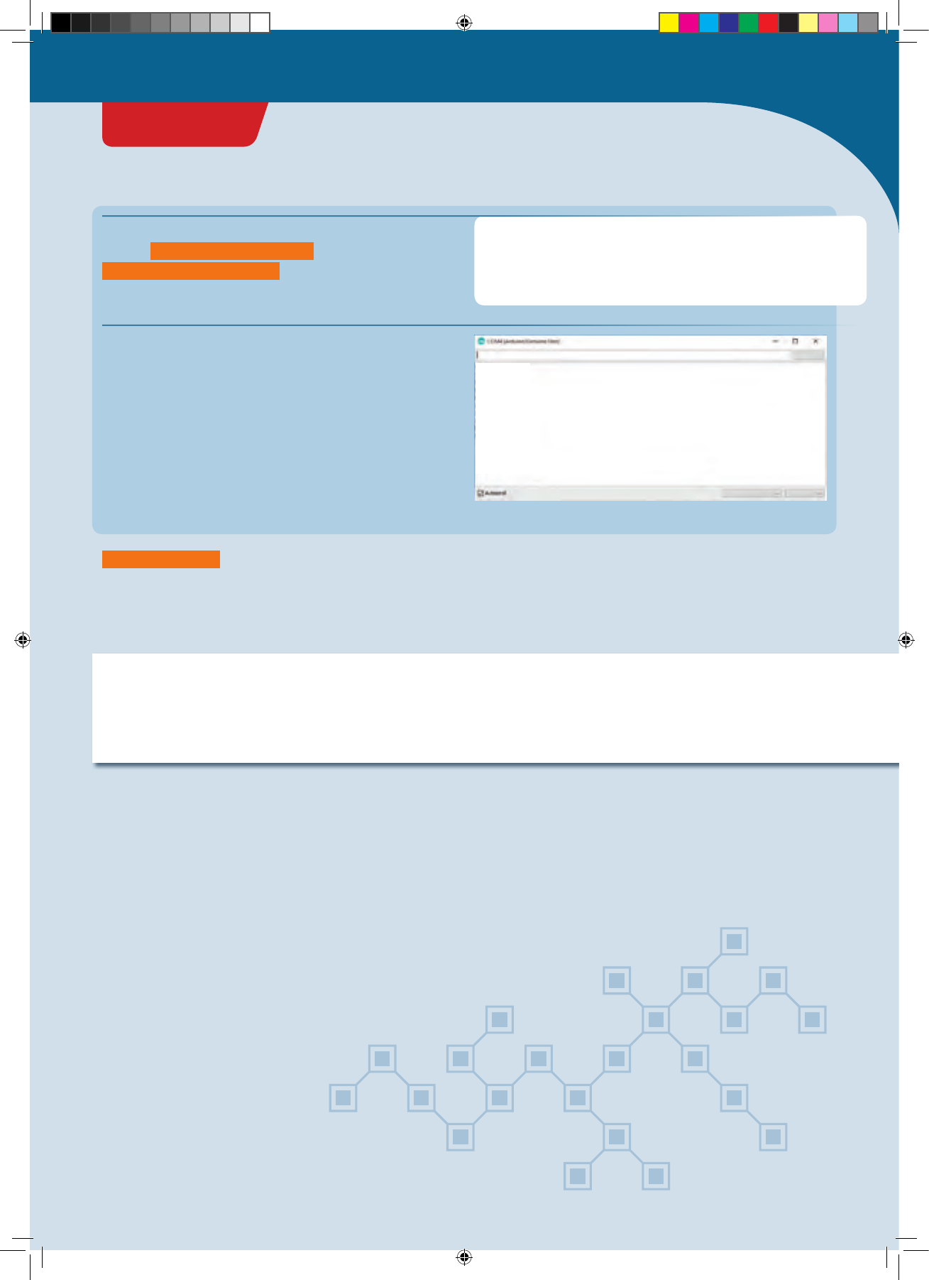
Upload the program to your KosmoDuino. Nothing will
seem to happen. Now click on the magnifying glass
symbol at the top right of the Arduino environment. A new
window will open for the serial monitor.
At first, you will probably just see some funny symbols.
You can fix that in a jiffy by setting the transmission rate
correctly. At the bottom right in the serial monitor, you
will find a drop-down list with a “115200 baud” option.
Select that, and you should see one “Hello!” after another
appear in the window.
▲A click on the magnifying glass at the
upper right will launch the serial monitor.
▲If the wrong baud rate is set (9600 baud in this
case), you will only see a jumble of symbols.
▲Once the right transmission rate is set, you can
receive “messages” from the KosmoDuino.
</>
÷ôôõôõõõôõôõõôõõôõõõôõõúúúôôõõõõõôô
Hello!Hello!Hello!
115200 Baud
9600 Baud
Senden
Senden
No line ending
No line ending
The serial monitor
YOU WILL NEED
› KosmoDuino
› Computer
› USB cable
THE PLAN
With the help of the serial monitor, you can send yourself
a brief message from your KosmoDuino and have it appear
on your computer screen.
To be able to use the serial monitor, proceed as follows:
THE PROGRAM
PROJECT 7
CodeGamer manual inside english.indd 28 7/19/16 12:32 PM
Now close the serial monitor. In the main loop, replace the
request Serial.print("Hello!"); with
Serial.println("Hello!"); :
void loop() {
Serial.println("Hello!");
delay(5 00);
}
Load the changed program to the controller and restart
the serial monitor. Each “Hello!” now gets its own line.
Serial.println() doesn’t just let you output previously
determined messages, though. It can also output newly
determined measurement readings. You will learn about
that in the project “Thermometer,” on page 33.
▲Unlike with Serial.print() you always get a new line with the
Serial.println() output..
</>
Hello!
Hello!
Hello!
Hello!
Hello!
Hello!
Hello!
Hello!
Hello!
Hello!
115200 Baud
Senden
No line ending
!
NOTE!
If you try to load a program to your KosmoDuino while the serial monitor is open, you may sometimes get an error
message. If that happens, close the serial monitor and try uploading the program again.
CodeGamer
PROJECT 7
CodeGamer manual inside english.indd 29 7/19/16 12:32 PM
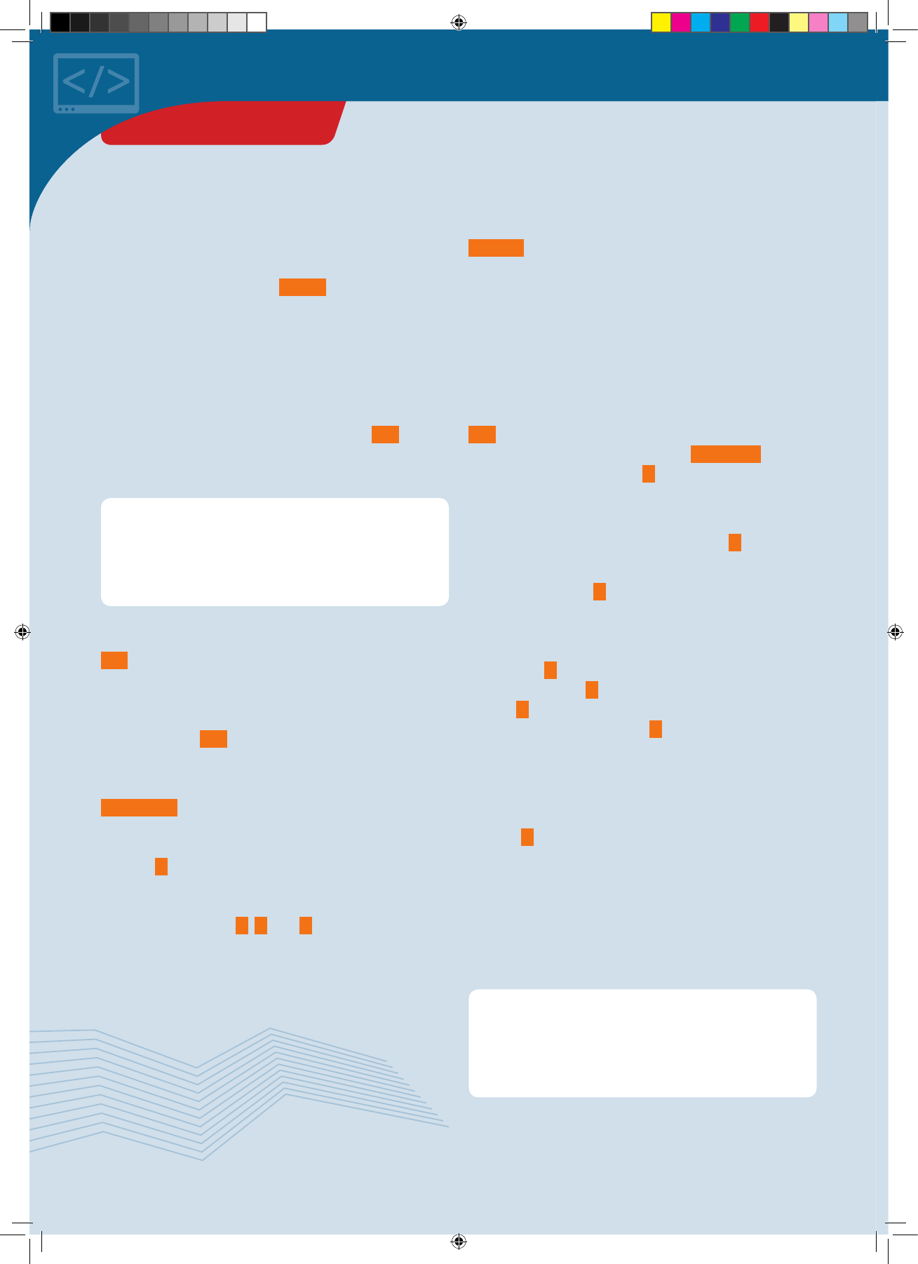
The for loop
When parts of a program are repeatedly carried out, you
call that a loop. You already learned about one import
kind of loop — the main loop, l o o p() . Your KosmoDuino
uses that to handle the most important tasks in your
program. It reads out input pins, processes the
measurement data, and then responds — over and over
again from the beginning.
You may often prefer, however, not to get caught in an
endless loop, and you might rather have just a certain
number of repetitions. For that, you can use a for loop.
You will usually be using it in the following manner as a
so-called counting loop:
i < 20; :
This is the test condition: Before each pass through the
loop, this condition is checked. If the condition is met, the
loop is passed through, meaning that the entire program
code inside the curly brackets is carried out.
If the condition is not met, the loop is abandoned: The
program code in the curly brackets is not carried again.
Instead, the program continues with the next instruction
following the loop.
++i :
First of all, this is an abbreviation for i = i + 1 . The
value of the counter variable i in other words, is
increased by 1. But when? After each pass through the
loop!
As long as the value of the counter variable i is not
changed, the following is what happens:
Before the first pass, i has the value 0. That is less than
20. So the test condition is met, and the loop is passed
through. After the instructions in the loop body have been
carried out, the value of the counter variable is raised by 1.
The value of i is now 1. The condition is still met, the loop
body is carried out, i is raised by 1 again and so on and so
forth. If i finally has the value of 19, the loop body is
carried out one more time and i is then increased to the
value of 20. The test condition is then no longer met, and
the loop is abandoned.
How often has the loop body now been carried out? It has
been carried out for the following values of the counter
variable i: 0, 1, 2, 3, ..., 19. The numbers 1 to 19 yield 19
passes, and one more pass is added for the value 0. So
there are 20 passes in all!
The counter variable, by the way, is not just there to count.
You can use its current value at any time in the loop body.
If, for example, you want to output all numbers from 1 to
42 on the serial monitor, you can do as follows:
for (int i = 0; i < 20; ++i) {
Instruction 1;
Instruction 2;
...
}
What does that mean? The loop is introduced by the word
for . The instructions that are carried out repeatedly are
in the block inside the curly brackets. This block with the
instructions to be repeated is often called the loop body.
For the loop to know how often to repeat these
instructions, the for loop needs some more information
— which you can find inside the parentheses. Let’s take a
closer look:
int i = 0; :
This is known as the initialization of the loop. Before the
loop is run through the first time, you apply the counter
variable i and give it the value of 0. You can give the
counter variable any name and starting value you like. As
long as the counter variable has no special meaning, you
usually use the letters i, j, and k as names. As a rule,
you generally start with the starting value of 0.
// Outputs the numbers 1, 2, 3,..., 42:
for (int i = 1 ; i <= 42; ++i) {
Serial.println(i); // Outputs the current
// value from i
}
THE FOR LOOP
CodeGamer manual inside english.indd 30 7/19/16 12:32 PM
Here, the loop starts with 2 and i = i + 2 raises the
counter variable by 2 after each pass through the loop.
Here, the loop starts with the starting value of 1. This time,
instead of testing whether i is less than 42, it tests
whether i is less than or equal to 42. That means that the
loop is also passed through one more time for the value of
42. But it also works in the opposite direction:
// Outputs the numbers 42, 41, 40, ..., 1:
for (int i = 42; i >= 1; --i) {
Serial.println(i);
}
The loop starts with the value of 42. It keeps running
through as long as i has a value that is greater or equal
to 1. The --i means that i is reduced by 1 after each
pass through the loop. In other words, it counts
backwards.
// Outputs the numbers 2, 4, 6, ..., 42:
for (int i = 2; i <= 42; i = i + 2) {
Serial.println(i);
}
You can actually use any instructions you like in place of
++i or --i . For example, you can just use even numbers:
THE FOR LOOP
CodeGamer
CodeGamer manual inside english.indd 31 7/19/16 12:32 PM
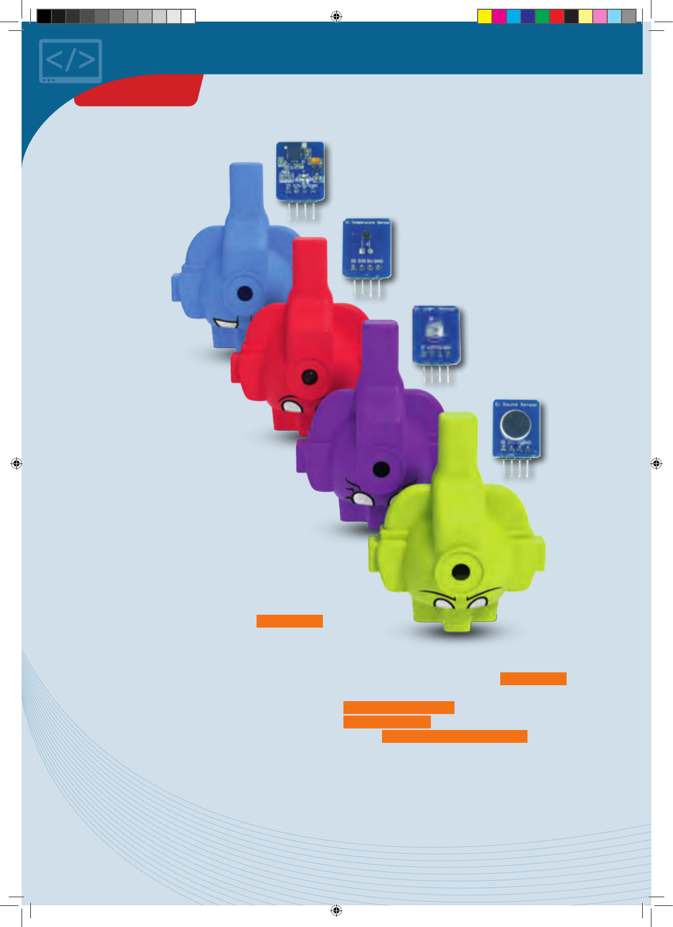
Temperature
sensor
Motion
sensor
Sound
sensor
Light
sensor
Sensors
So far, you have learned how
your KosmoDuino can react to
the push of a button. In this
experiment kit, though,
you will also find a
lot of sensors that
can be used to
help your
microcontroller
respond to its
environment. These
are the KosmoBits
modules!
Your controller can use the
temperature sensor to monitor
the temperature, while the light
sensor monitors brightness. The
motion sensor lets you record even the
slightest movements of the KosmoDuino,
and the sound sensor lets you listen for
noises.
But how does the KosmoDuino get the
information from the sensors? How does it learn
how warm or how bright it is?
Simple: The sensors relay their measurement readings to
the microcontroller in the form of electrical voltage. The
microcontroller can then read this voltage through one of
the pins. A lot of the pins can do a lot more than distinguish
“on” from “off.” They can also measures different voltage
levels. That’s what is handled by the order
analogRead()
,
which lets you determine the voltage at a pin. The result is
a numerical value from 0 to 1023. The higher the voltage
arriving at a pin, the greater the numerical value. 0
indicates no voltage at all, while 1023 indicates 5 volts.
Of course, you will also have to tell analogRead() which
pin to read. In general, it will be the
KOSMOBITS_SENSOR_PIN , which is defined in the
KosmoBits_Pins.h file. So you should always link this
file with #include <KosmoBits_Pins.h> if you want to
access the KosmoBits sensor modules.
You have already learned about the serial monitor. It’s an
important tool for working with the sensors. See the next
projects to find out why.
SENSORS
CodeGamer manual inside english.indd 32 7/19/16 12:32 PM
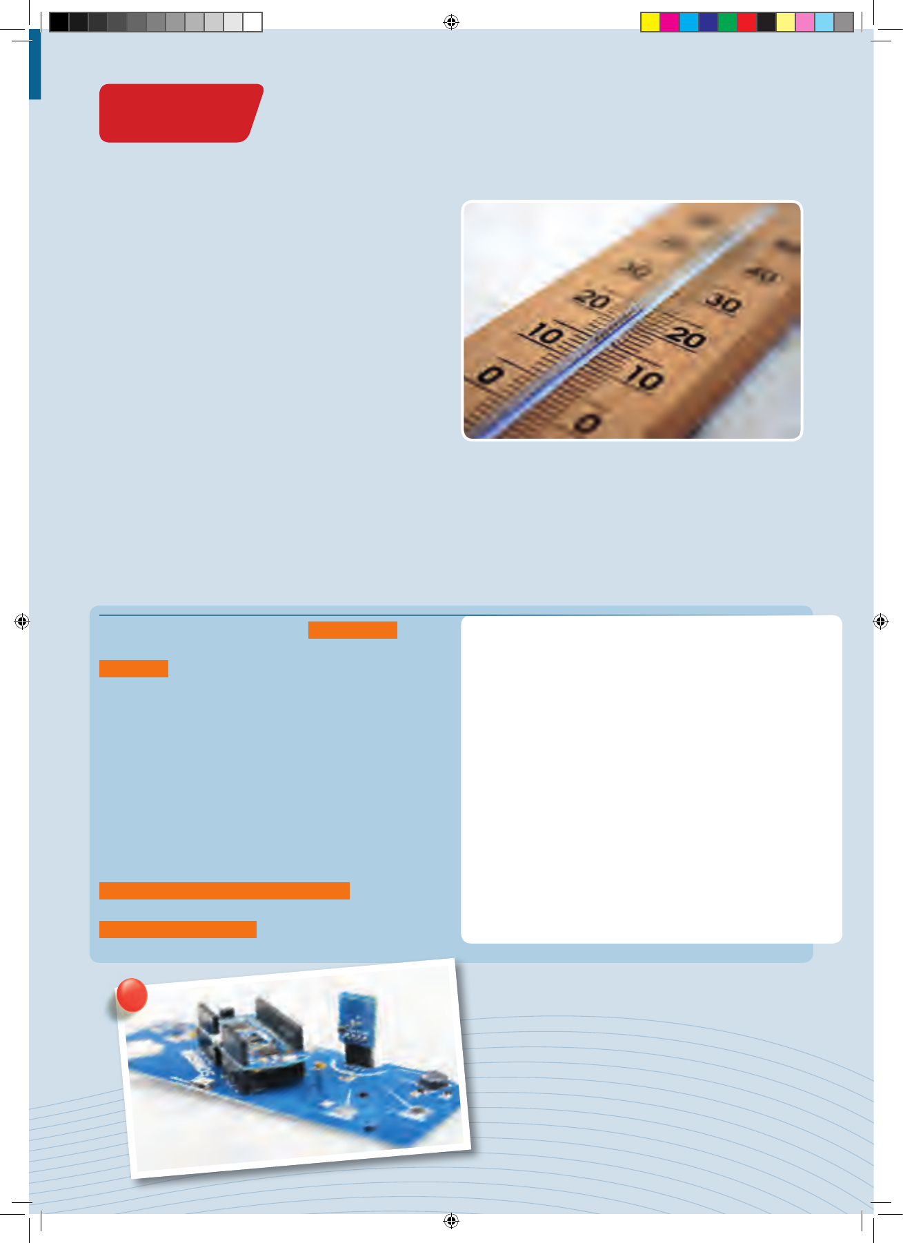
Thermometer
YOU WILL NEED
› KosmoDuino in the interaction board
› Temperature sensor
PREPARATION
Mount the temperature sensor on the interaction board.
THE PLAN
In this project, you will be turning your KosmoDuino into a
thermometer for measuring the temperature with the help
of the temperature sensor. The temperature is output via
the serial monitor.
The program is easy to explain. The analogRead()
portion ensures that the voltage is repeatedly read at the
sensorPin . The measurement reading is then output
through the serial monitor. You will be using this program
whenever you want to learn about a new sensor.
So open the serial monitor and take a look at the
measurement readings. Place your finger on the black dot
sticking up out of the sensor housing. You should see the
measurement readings change. It won’t yet look like a
temperature reading, though. You still have to convert the
measurement readings into temperatures. The KosmoBits
library can help you with that. It includes a function for
that very task, called
thermistor_measurement_in_celsius() .
To use this function, you will first have to link the
KosmoBits_Thermistor.h file.
#include <KosmoBits_Pins.h>
const int sensorPin = KOSMOBITS_SENSOR_PIN;
void setup() {
pinMode(sensorPin, INPUT);
Serial.begin(115200);
}
void loop() {
int value = analogRead(sensorPin);
Serial.print("measurementReading: ");
Serial.println(valu e);
delay(1000);
}
</>
THE PROGRAM
Now, write the following code and upload it to the controller:
◀Board with temperature sensor
CodeGamer
PROJECT 8
CodeGamer manual inside english.indd 33 7/19/16 12:32 PM

SO CHANGE YOUR PROGRAM LIKE THIS:
Close the serial monitor, upload the program, and reopen
the serial monitor. You will see that the current
temperature is now being output at regular intervals.
#include <KosmoBits_Pins.h>
#include <KosmoBits_Thermistor.h>
const int sensorPin = KOSMOBITS_SENSOR_PIN;
void setup() {
pinMode(sensorPin, INPUT);
Serial.begin(115200); // Enable output via
// serial monitor.
}
void loop() {
int measurement = analogRead(sensorPin);
float celsius = thermistor_measurement_in_
celsius(measurement); // C o n v er t
// measurement into degrees Celsius.
Serial.print(celsius); // Celsius value
// is output.
Serial.println(" degrees Celsius"); // Output
// of"Degrees Celsius" and line break.
delay(1000);
}
</>
PROJECT 8
CodeGamer manual inside english.indd 34 7/19/16 12:32 PM
You have already learned a little about numbers and
variables that can incorporate numbers. They aren’t
much use, however, if you can’t use them to calculate.
After all, you will normally be using your KosmoDuino
to read a numerical value from a sensor and then using
that to control something else. To do that, you have to
be able to calculate another numerical value from the
measurement.
In the Arduino programming language, all the basic
calculation types are available to you for this. For
adding and subtracting, you use the typical “+” and “-“
symbols. For multiplication, use a star (“*”). For
division, use a simple forward slash (“/”).
By the way, you can also use the previous value of a
variable to calculate something new with it:
There is even an abbreviation for the frequently used
calculation step
i = i + 1;
:
CALCULATING IN THE PROGRAM:
// Addition (plus)
int x; // x is a whole number.
x = 1 + 4; // x has the value 5.
// Subtraction (minus)
x = 5 - 3; // x has the value 2.
// Multiplication (times)
x = 3 * 4; // x has the value 12.
// Division (divided by)
x = 12 / 6; // x has the value 2.
// Follow order of operations
x = 4 * 3 + 2; // x has the value 14.
int x = 4;
x = x + 2; // x has the value 6.
x = 2 * x; // x has the value 12.
int i = 0;
i++; // means x = x + 1.
++i; // also means x = x + 1.
KNOWLEDGE BASE
CodeGamer
CodeGamer manual inside english.indd 35 7/19/16 12:32 PM
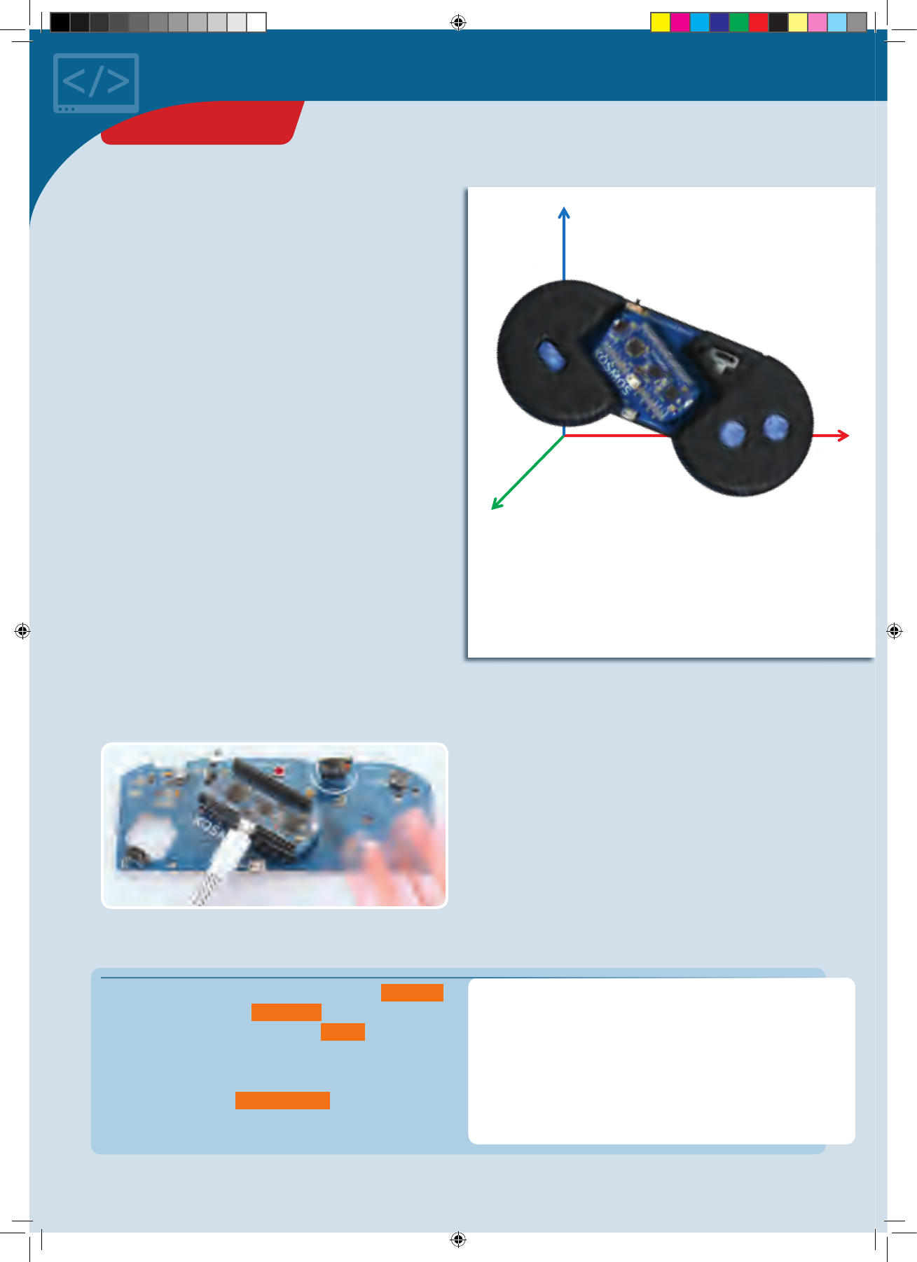
X
Y
Z
THE PROGRAM
Finger disco
YOU WILL NEED
›
KosmoDuino in the
interaction board
› Motion sensor
PREPARATION
With the motion sensor, your KosmoDuino will be able to
record even the tiniest movements. To develop the proper
feel for it, start by inserting the motion sensor into the
interaction board. Then upload the “ReadSensor” sketch to
your KosmoDuino.
You will now be able to observe the motion sensor’s readings
in the serial monitor. As long as you do not move the
controller, the reading will just fluctuate slightly around an
average value.
Now try moving the controller in different directions and
rotating and tipping it. You will see how there are
movement and rotation directions that cause the reading
to change sharply. In other directions the reading may
hardly change at all.
Now try drumming gently, and then somewhat more
strongly with your fingers on the interaction board housing.
Start by linking to the required libraries via the #include
instructions, defining the sensorPin to be able to read
the sensor readings, and defining the pixel in order to be
able to control the NeoPixel.
To be able to recognize deviations from a resting state, you
still have to define the restingValue variable. The
resting average will be saved there.
#include <Adafruit_NeoPixel.h>
#include <KosmoBits_Pins.h>
#include <KosmoBits_Pixel.h>
const int sensorPin = KOSMOBITS_SENSOR_PIN;
KosmoBits_Pixel pixel;
int restingValue = 0;
In fact, the sensor merely measures the sensor’s
acceleration along the so-called z-axis, or the “forward-
and-backward axis.” That’s why the reading changes
when you move the controller away from you or back
towards you. Up-and-down movements, on the other
hand, will not change the reading
.
▲Fingers drum on the board and the NeoPixel blinks.
Even though the shaking caused by your fingers is very
slight, it is registered by the sensor. If you place the
controller on a table, you can even trigger the sensor by
just drumming on the table.
We can make use of this to turn your KosmoDuino into a
finger-drumming disco lighting device. To do that, use the
following program:
THE PLAN
Bright lights dancing in rhythm to your fingers. With this
project, you will be able to turn your KosmoDuino into a
Finger Disco.
PROJECT 9
CodeGamer manual inside english.indd 36 7/19/16 12:32 PM
X
Y
Z
int determineRestingValue() {
const int N = 20; // measurement numbers
float average = 0;
for (int i = 0; i < 20; ++i) {
average = average + analogRead(sensorPin);
delay(10);
}
average = average / N;
return average;
}
void setup() {
pinMode(sensorPin, INPUT);
restingValue = determineRestingValue();
}
void loop() {
int value = analogRead(sensorPin);
int difference;
if (value > restingValue) {
difference = value - restingValue;
} else {
difference = restingValue - value;
}
pixel.setColor(2 * difference, 100 - 2 *
difference, 0, difference); // RGB value and
// b ri g h tn e ss.
delay(10);
}
</>
To determine the resting value, calculate the average of 20
readings. The number of readings will be saved in the N
constant, so it can easily be changed. The average is stored
in the average variable.
You know all about the for loop now. It will be passed
through N times, or 20 times in this case.
With each pass through the loop, another measurement
reading will be added to the current average . There is a
pause of 10 milliseconds before each subsequent reading
When the loop is abandoned, the sum of the 20
measurement readings is saved in the average variable.
To calculate the average from that, the total must be
divided by the number of readings. That happens in the
average = average / N; line.
Finally, return average; returns the calculated
average.
It’s simple: pinMode(sensorPin, INPUT); sets the
sensorPin as the input pin. Finally, the resting value is
calculated and stored in the restingValue variable.
In the main loop, a current sensor value is first read and
saved in value . Now it’s time to determine the deviation
from the average and save it in the difference variable.
The deviation always has to be positive. Since you don’t
know if the current sensor reading is greater than or less
than restingValue , the if instruction will be used to
decide between two cases: If value is greater than
restingValue , difference is calculated as
value - restingValue ; otherwise, it is calculated as
restingValue - value .
Now, pixel.setColor() is used to set the NeoPixel color
independently of the difference value: The greater the
difference, the higher the red portion, and the lower the
green portion.
Do you have your own ideas about
how the NeoPixel color should react
to the deviation from the resting
value? Try it! You’re sure to come up
with all sorts of interesting
variations.
PROJECT 9
CodeGamer
CodeGamer manual inside english.indd 37 7/19/16 12:32 PM
</>
Cheep!
You can also use the interaction board to produce sounds.
This little project will show you how it works.
YOU WILL NEED
› KosmoDuino
in the interaction board
THE PLAN
So far, the KosmoDuino just beeps at regular intervals.
Don’t worry — you will learn how to turn it into a siren or
even a musical instrument.
THE PROGRAM
Start by including the KosmoBits_Pins.h file and
defining the buzzerPin constant in order to address the
pin to which the “buzzer” (the miniature speaker) is
connected.
#include <KosmoBits_Pins.h>
const int buzzerPin = KOSMOBITS_BUZZER_PIN;
void setup() {
// Nothing to do.
}
void loop() {
tone(buzzerPin, 440);
delay(5 00);
noTone(buzzerPin);
delay(5 00);
}
This time, you won’t have to do anything in s e t u p() .
The composition of the lo o p () will probably look
familiar to you. It matches the “Blink” program, which
was the very first program that you uploaded to your
KosmoDuino. But this time, instead of making an LED
blink, you will be making sounds. These two commands
will help:
tone(buzzerPin, 440); produces a tone with a
frequency of 440 Hz. This is the standard pitch of A. The
tone stays on until you switch it off again with
noTone(buzzerPin); To switch the tone on and off again
at regular intervals, use del ay(50 0); to attach a half-
second pause to each of these commands.
C
h
e
e
p
!
C
h
e
e
p
!
PROJECT 10
CodeGamer manual inside english.indd 38 7/19/16 12:32 PM
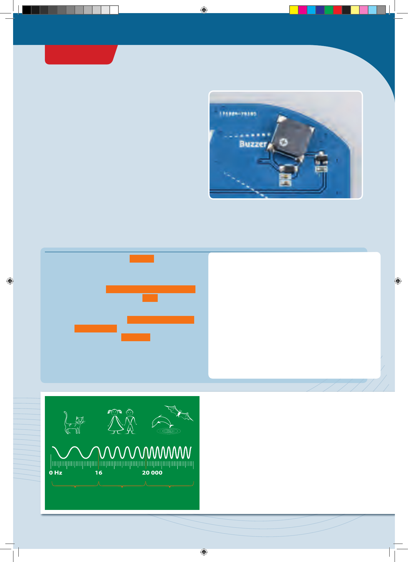
Infrasound Audible
Frequencies
Ultrasound
</>
Random sounds!
You just learned in the “Cheep!” project how to make your
KosmoDuino start beeping. But it can get a little boring
listening to the same tone over and over. Here’s where you
learn how to get random sounds out of your controller.
YOU WILL NEED
› KosmoDuino
in the interaction board
THE PLAN
The random generator will determine the pitch of the
tones as well as their duration.
THE PROGRAM
The program is pretty simple. In s e t u p() , you give the
random generator a starting value just as you did in the
die-rolling project.
Then, in the main loop, int freq = random(110,1000);
randomly determines the frequency ( freq ) of the next
tone, and then its duration in the same manner.
Finally, the tone is output with tone(buzzerPin,freq); .
At the end, delay(dau er); ensures that the tone is played
for the duration indicated by duration .
#include <KosmoBits_Pins.h>
const int buzzerPin = KOSMOBITS_BUZZER_PIN;
void setup() {
randomSeed(analogRead(12));
}
void loop() {
int freq = random(110, 1000);
int duration = random(10, 150);
tone(buzzerPin, freq);
delay(duration);
}
!
SOUND
When the air pushing against our ear drums vibrates back
and forth, we perceive it as sound. The faster the air
vibrates, the higher the sound. Physicists measure that as
“vibrations per second,” or frequency. The unit of frequency
is known as a Hertz, abbreviated Hz. One Hertz means that
the air completes one full oscillation (vibration back and
forth) per second. The higher the frequency of a sound, the
higher the pitch of the sound we hear. Humans can perceive
sounds with frequencies between 16 and 20,000 Hertz. A
lot of animals, on the other hand, are able to perceive
sounds in the infrasonic and ultrasonic range.
CodeGamer
PROJECT 11
CodeGamer manual inside english.indd 39 7/19/16 12:32 PM
</>
Siren
Now it’s time to bring some order to the acoustic chaos.
This project will let you make your KosmoDuino howl like
a siren.
YOU WILL NEED
› KosmoDuino
in the interaction board
Here’s where you specify the frequency range within
which the sound pitch is to move. FREQ_MIN corresponds
to the deepest sound of the siren, and FREQ_MAX the
highest. You can also experiment with these parameters
by changing the values, and find a siren noise to suit your
taste.
DELAY determines how long any given sound will be held.
The variable freq finally, saves the current frequency.
The siren starts at FREQ_MIN .
#include <KosmoBits_Pins.h>
const int buzzerPin = KOSMOBITS_BUZZER_PIN;
const int FREQ_MIN = 440;
const int FREQ_MAX = 660;
const int DELAY = 4;
int freq = FREQ_MIN; // Frequency of the sound
// that is output.
void setup() {
// Nothing to do here.
}
void loop() {
tone(buzzerPin, freq); // (1)
delay(DEL AY);
++freq; // Short for: freq = freq + 1;
if (freq > FREQ_MAX) {
freq = FREQ_MIN;
}
}
This time, you won’t have to do anything in s e t u p() .
The main loop starts by outputting a sound with the
frequency freq (1). After a pause of length DELAY , the
frequency freq is raised by 1 with ++freq; . The if
instruction then checks whether the maximum frequency
has been exceeded. If so, the frequency freq is returned to
the starting value FREQ_MIN .
In the next project, you will be producing an entire musical
scale. But first you will have to learn about an important
programming tool: Arrays.
THE PLAN
With every pass through the main loop, a new sound will
be output. Each time, the pitch will be raised a little. Once
a certain frequency, or sound pitch, is attained, the pitch
drops back to its starting value and the whole thing starts
over from the beginning.
THE PROGRAM
PROJECT 12
CodeGamer manual inside english.indd 40 7/19/16 12:32 PM
Arrays
If you want to save a lot of values of the same type, for
example the last 100 values, it can be pretty time-
consuming and confusing to have to enter all that in.
You would have to apply a separate variable for each
individual value, as follows:
int value 1;
int value 2;
int value 3;
...e t c...
int value 100;
It’s a lot simpler to use what’s called an array.
In an array, you can store many values at one time. To
make it possible to access the individual variables in
the array, they are all consecutively numbered. So you
can think of an array as a kind of table in which the
individual values are entered into numbered columns.
The numbering of the columns, however, starts with 0
rather than 1:
INDEX 0 1 2 3 … n
VALUES Value 0 Value 1 Value 2 Value 3 … Value n
In general, an array is created as follows:
type arrayName[length];
You can also assign values to an array by specifying
the individual values in curly brackets:
The type specifies which type of data can be saved in the
array (int, float, etc.). The number of values that can be
stored in an array is known as its length.
int myArray[10]; // An array that can
// take 10 int values
int myArray[4] = {0, 4, 2, 3};
In that case, you don’t necessarily have to indicate
how many values there are. You can also write:
int myArray[] = {0, 4, 2, 3};
So, for example, to create an array that can take 10
integer values, you proceed as follows:
KNOWLEDGE BASE
An array is sometimes called a Field or
Data Field. However the term Array is
the much more common name.
CodeGamer
CodeGamer manual inside english.indd 41 7/19/16 12:32 PM
You will often want all individual values to be set to
zero. You can do that quickly by writing as follows:
int myArray[10] = {}; // Array of
// length 10 with all the values
// set to 0.
To access the individual values of an array, you indicate
the value in square brackets for the index that you want
to access. So if you think of the array as a table, the
index corresponds to the column number.
int myArray[100] = {}; // Array of
// length 100 with all values set to 0.
myArray[2] = 42; // The value at index
// position 2 is now 42.
int x = myArray[2]; // x contains the
// value saved at index position 2
// in myArray, in this case it is 42.
You may often want to calculate a new value from all
the individual ones, for example the sum of all
individual values. Since you can now address the
individual values via their index, you can easily do this
with a
for
loop:
// values is an array of length 100.
int sum = 0;
for (int index = 0; index < 100;
++index) {
sum = sum + values[index];
}
With the first pass through the loop, the value
values[0]
is added to
sum
. Then,
index
is raised by
1, and the next value is added. This is repeated until
the last value (
valu es[99]
) has been added.
In the next project, you will use an array to play a
musical scale.
!
NOTE!
Since the index for the first value is 0 rather than 1, the
highest possible index for an array of length N is not N,
but rather N-1. With an array of length 100, in other
words, the highest possible index would be 99. If you use
a higher index, it will result in an error in the program
sequence. It’s impossible to predict what would happen
then. So be careful only to use valid values for the index.
KNOWLEDGE BASE
CodeGamer manual inside english.indd 42 7/19/16 12:32 PM
</>
Musical scale
YOU WILL NEED
› KosmoDuino
in the interaction board
THE PLAN
Your KosmoDuino will play a musical scale.
THE PROGRAM
First you include the KosmoBits_Pins.h file and define
the buzzerPin and freqRoot constants. Finally, you
apply the scale[] array, in which the frequency
relationships of the notes of a major-key scale will be
placed. To determine the frequency of a note, you will
have to multiply the corresponding value by the frequency
of the root chord.
#include <KosmoBits_Pins.h>
const int buzzerPin = KOSMOBITS_BUZZER_PIN;
const int freqRoot = 220; // This is the
// note A (one octave deeper than the standard
// pitch A from project 10).
float scale[] = {1.f, 9.f/8, 5.f/4, 4.f/3, 3.f/2,
5.f/ 3, 15.f/8, 2.f};
void setup() {
for (int i = 0; i < 8; ++i) {
tone(buzzerPin, scale[i] * freqRoot);
delay(5 00);
}
noTone(buzzerPin);
}
void loop() {
// Nothing is done here.
}
This time, everything is happening in s e t u p () . In the for
loop, the variable i is counted up from 0 to 7. For each
value of i then, the i-th note of the scale is output with
tone(buzzerPin, scale[i] * freqRoot); . As
described above, the frequency of the root chord
freqRoot is multiplied by the corresponding frequency
relationship s c al e[i] to determine the right frequency.
After a pause, the for loop is passed through again until
the highest note of the scale is reached. Then it’s quiet:
noTone(buzzerPin); .
This time, nothing is done in the main loop. The scale is just
played through a single time, in other words. To make the
scale play again, you can press the reset button on the
KosmoDuino. That will reset the code and carry it out
again from the beginning.
PROJECT 13
CodeGamer
CodeGamer manual inside english.indd 43 7/19/16 12:32 PM
Sensor organ
Now that you have learned how to play musical scales,
it’s time to program an actual musical instrument.
YOU WILL NEED
› KosmoDuino in the interaction board
› Motion sensor
#include <KosmoBits_Pins.h>
const int sensorPin = KOSMOBITS_SENSOR_PIN;
const int buzzerPin = KOSMOBITS_BUZZER_PIN;
const int buttonPin = KOSMOBITS_BUTTON_2_PIN;
const float scale[] = {1.f, 9.f/8, 5.f/4, 4.f/3,
3.f/2, 5.f/ 3, 15.f/8, 2.f};
const int freqRoot = 220; // This is the
// note A.
const int measurementMin = 300;
const int measurementMax = 400;
const int scaling = (measurementMax -
measurementMin) / 9;
const int N = 10; // Number of values that
// are averaged.
int values[N] = {}; // Here is where the last
// 10 values are stored.
int index = 0;
This is where each of the pin modes is set. void setup() {
pinMode(sensorPin, INPUT);
pinMode(buttonPin, INPUT);
}
void loop() {
// Reads a new value from the sensor and
// saves it in values[].
values[index] = analogRead(sensorPin);
First, you will define a few constants for sensor pin,
buzzer pin, and button pin. Then, as you did in the last
project, you will apply an array for the scale as well as a
constant for the root chord.
With the measurementMin and measurementMax
constants, you will be regulating how far the controller
has to be tipped in order to play the highest or the lowest
note. You can adjust these values to suit your own
preferences later on. You will be using the scaling
constant later on to determine the pitch from a
measurement reading, dividing practically the entire
measurement range into 9 portions.
The motion sensor is quite sensitive, so the readings will
fluctuate a little. To keep the pitch from wavering too
much, you won’t be taking the last reading to measure the
pitch. Instead, you will be calculating the average of 10
readings. The last 10 measurement readings will be saved
in the values[] array for this purpose. All values in it will
first be set to 0 by int values[N] = {}; .
With the index variable, the array will be run through,
starting with 0 as usual.
THE PLAN
You will produce musical notes at the push of a button.
The pitch of the note can be changed by moving the
interaction board. With a little practice, you can play an
actual melody this way.
</>
THE PROGRAM
You will start by taking a new measurement reading and
saving it in the values array at the index position. To
ensure that the next measurement reading is saved at the
subsequent position, ++index; raises the index by 1. If
the value of N is reached, the if instruction sets index
PROJECT 14
CodeGamer manual inside english.indd 44 7/19/16 12:32 PM
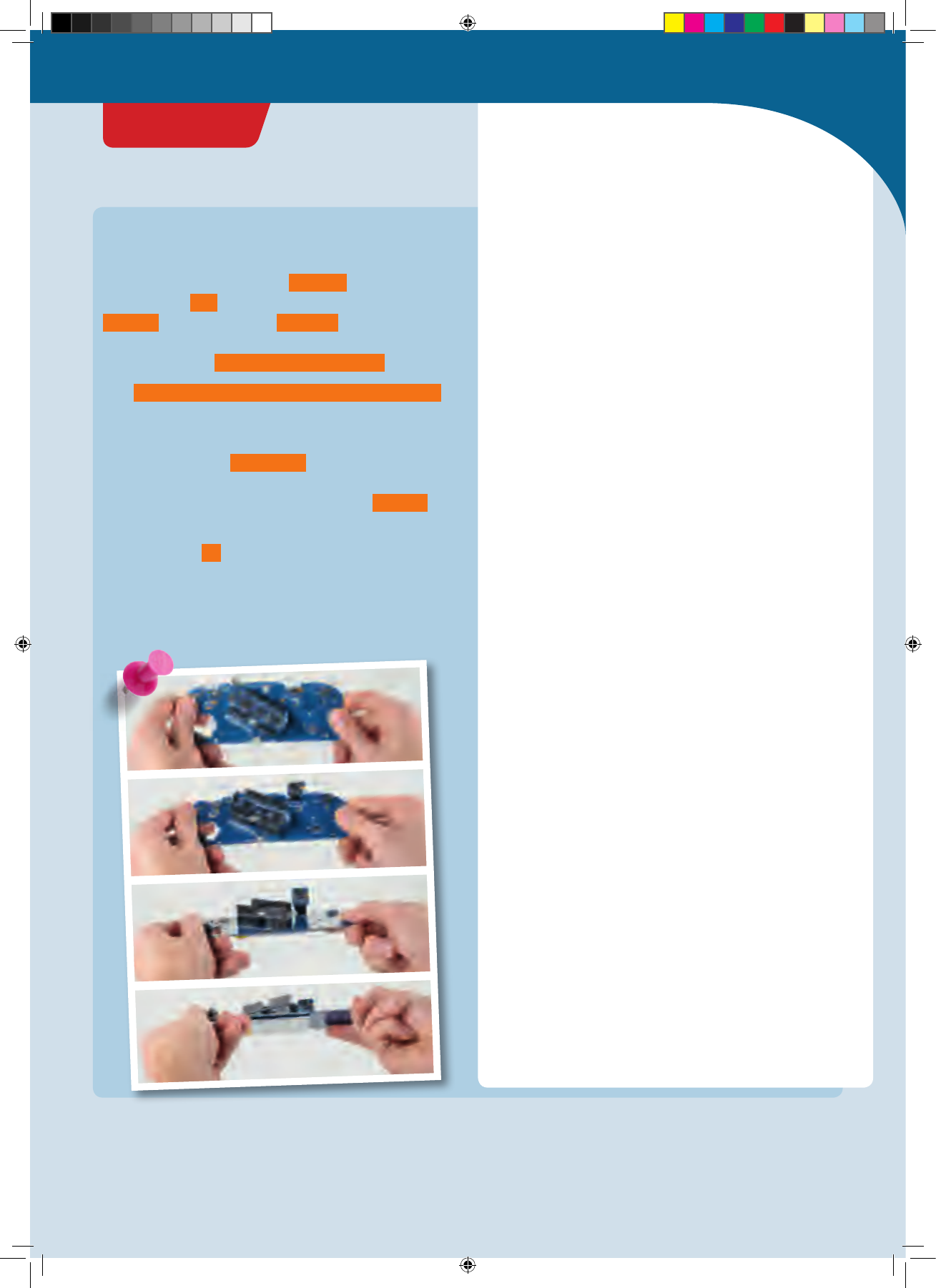
Admittedly, this was a little more involved.
But the results make it all worthwhile!
// Raise the index by 1, so the next
// value can be saved at the next location
// in the values[] field.
++index;
// If index == N, the field is
// fully described.
// index is then set to 0, so that
// the oldest value
// is overwritten in the next pass.
if (index == N) {
index = 0;
}
// Now the average of the last N
// measurement readings is calculated.
int average = 0; // Start with the value 0
// Total the measurement values.
for (int i = 0; i < N; ++i) {
average = average + values[i];
}
// Divide the total by the number of values.
average = average / N;
int noteIndex = (average - measurementMin) /
scaling;
// noteIndex must not be less than 0 or
// greater than 7:
if (noteIndex < 0) {
noteIndex = 0;
} else if (noteIndex > 7) {
noteIndex = 7;
}
// Output note
if (digitalRead(buttonPin) == LOW) {
tone(buzzerPin, scale[noteIndex] * freqRoot);
delay(10);
} else {
noTone(buzzerPin);
delay(1);
}
}
</>
back to 0. The array is filled from the beginning again.
Then it’s a matter of determining the average of the last 10
measurements. To do that, the average variable is first
set to 0. In the for loop, then, all the values saved in the
valu e[] array are added to average . To calculate the
average from that, the result has to be divided by the
number of values: average = average / N; .
With int noteIndex = (average - measurementMin) / scaling; ,
you will be determining the “note index”: Which note in the
scale sequence should be played?
It might happen that noteIndex has an invalid value —
in other words, that it is less than 0 or greater than 7.
That’s why you will be correcting it with the if-else
instruction in case of doubt.
Finally, the last if query checks whether the button is
pushed. If so, the corresponding note is output. If not, no
note is output.
CodeGamer
PROJECT 14
CodeGamer manual inside english.indd 45 7/19/16 12:32 PM
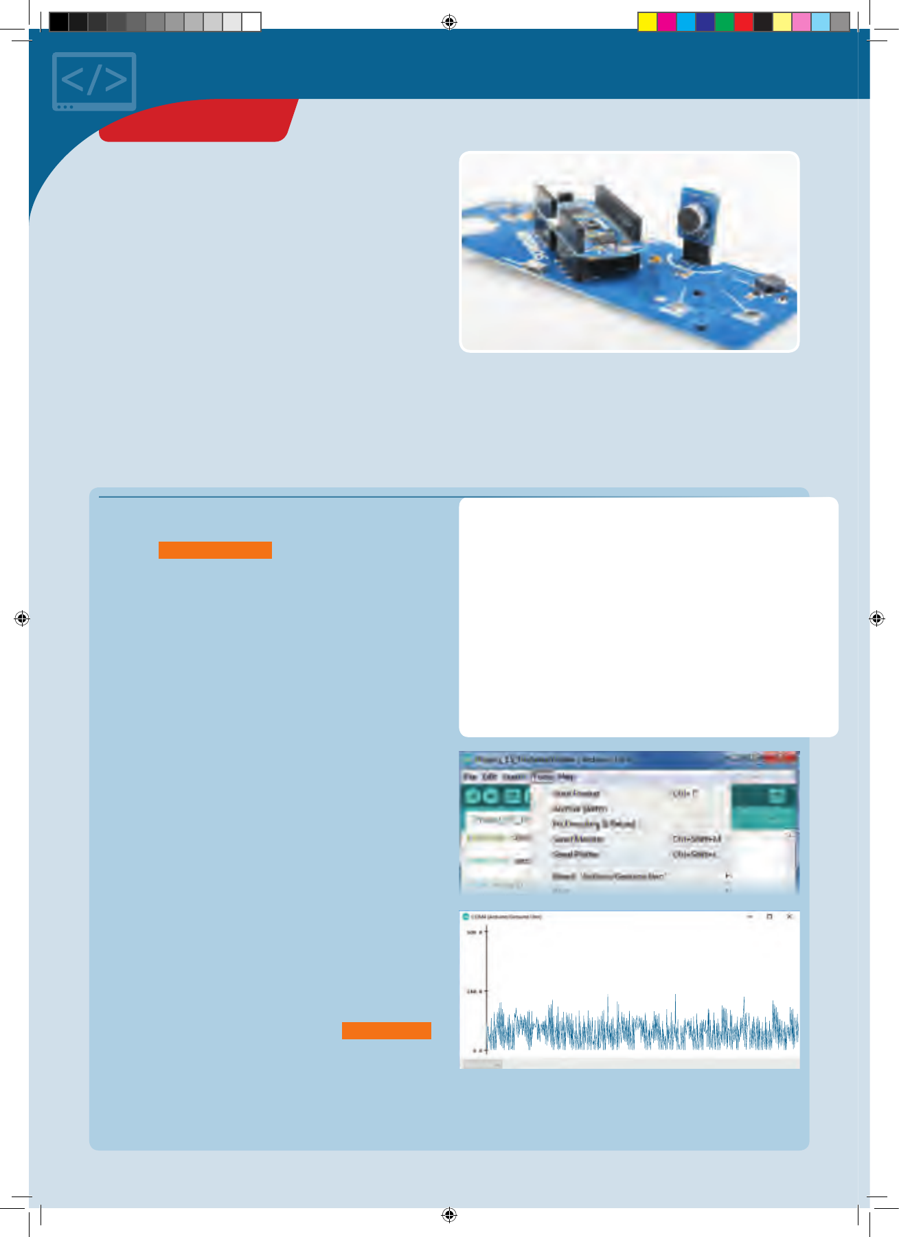
There isn’t a whole lot that the code does. With each pass
of the main loop, a new value is read by the sensor pin and
output by Serial.println() .
#include <KosmoBits_Pins.h>
const int sensorPin = KOSMOBITS_SENSOR_PIN;
void setup() {
pinMode(sensorPin, INPUT);
Serial.begin(115200);
}
void loop() {
Serial.println(analogRead(sensorPin));
}
The serial plotter
YOU WILL NEED
› KosmoDuino in the interaction board
› Sound sensor
THE PLAN
The sound sensor is basically a small microphone that you
can read via the sensor pin. To understand how it works,
115200 Baud
Now start the Serial Plotter from the “Tools” menu. (If you
do not see the Serial Plotter in the Tools menu, you may
need to update your Arduino software to a newer version.)
A new window will open with some crazy-looking things
happening.
Now try to make various sounds, such as whistling or
singing. You will see how the image changes in the serial
plotter.
The scale along the left edge makes it easy to read the
magnitude of the values delivered by the sensor. In the
example shown here, you can see that 0 is the lowest
value. That should be obvious — after all analogRead()
wouldn’t be able to deliver anything smaller. The largest
measured reading is about 250. But if you clap your hands,
the readings may rise to 800.
You will be able to make excellent use of this in your next
project.
</>
THE PROGRAM
Plug the sound sensor into the interaction board and then upload the following little program to your KosmoDuino:
the best thing is to use another cool tool from the Arduino
environment — the serial plotter.
PROJECT 15
CodeGamer manual inside english.indd 46 7/19/16 12:32 PM
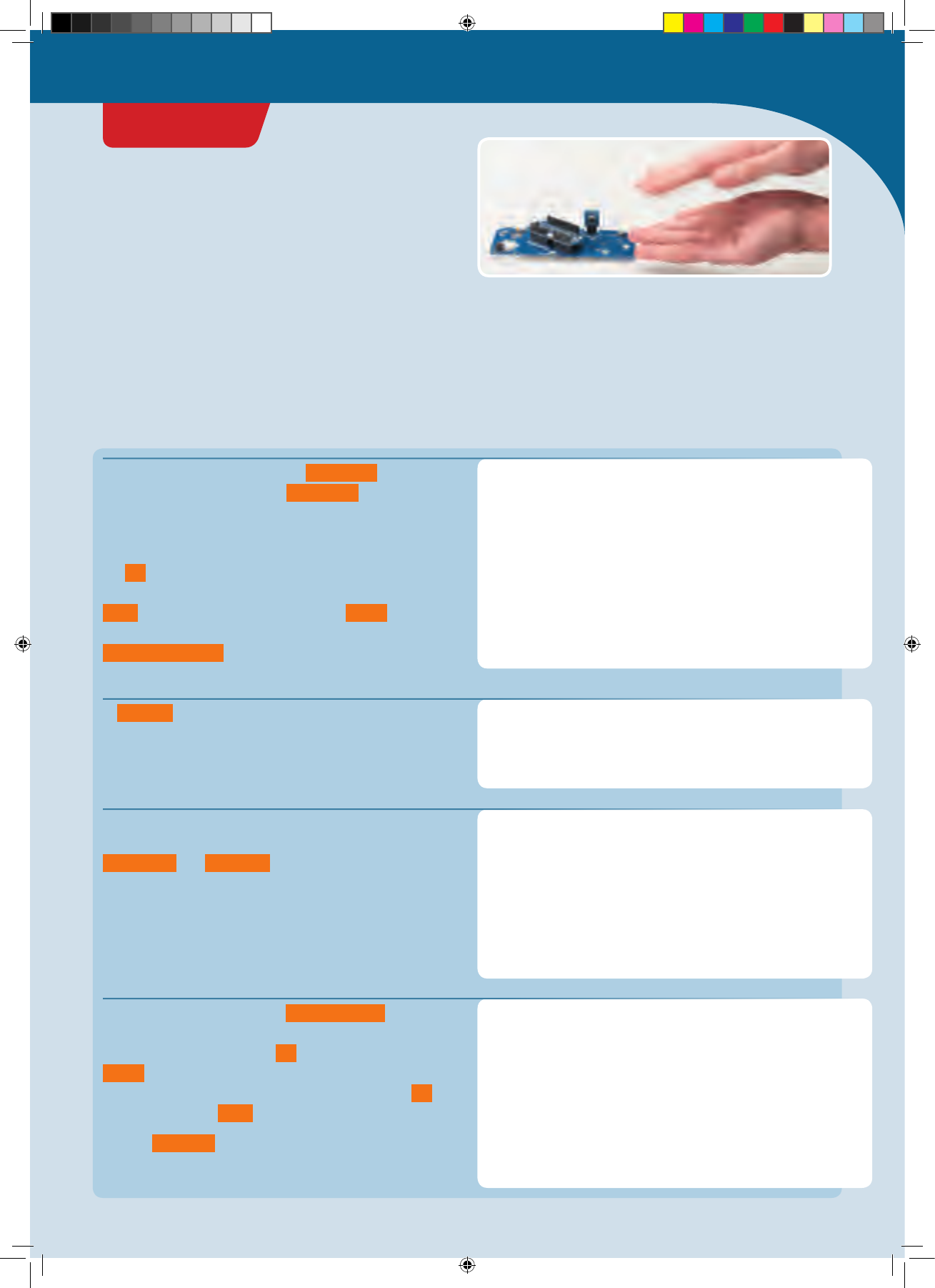
Clap switch
Wouldn’t it be cool if your KosmoDuino could respond to
clapping? You can easily program it to do that with the
help of your sound sensor.
YOU WILL NEED
› KosmoDuino in the interaction board
› Sound sensor
#include <KosmoBits_Pins.h>
#include <Adafruit_NeoPixel.h>
#include <KosmoBits_Pixel.h>
const int sensorPin = KOSMOBITS_SENSOR_PIN;
const int threshold = 500;
KosmoBits_Pixel pixel;
bool on = false;
In s e t u p () , the pin mode of the sensor pin is set and the
NeoPixel is switched off.
void setup() {
pinMode(sensorPin, INPUT);
pixel.setColor(0, 0, 0, 0);
}
void loop() {
int sensorValue = analogRead(sensorPin);
Serial.println(sensorValue);
if (sensorValue > threshold) {
t o g gl e();
delay(200);
}
}
void toggle() {
if (on) {
pixel.setColor(0, 0, 0, 0);
on = false;
} else {
pixel.setColor(255, 0, 0, 30);
on = true;
}
}
The usual files are linked and the sensorPin constant is
defined for the sensor pin. The threshold constant
controls the sensitivity of your clap switch. If the value set
there is exceeded by the measurement reading, the switch
toggles over — either from “on” to “off” or vice-versa. In
the on variable, you will be storing the current state of
the NeoPixel. If it is on, the variable is assigned the value
true , otherwise it is assigned the value false . At the
beginning of the program, the NeoPixel is off:
bool on = false; .
</>
THE PROGRAM
In the main loop, the sound sensor is continuously read. If
the measured value is greater than the value set in
threshold , the t o g gl e() function is invoked and there
is a brief pause.
Here, you will write your own v oi d t o g gle () function.
This queries whether the NeoPixel is currently on. If so, the
NeoPixel is switched off and on is assigned the value
false .
Otherwise (“else”), the NeoPixel is switched on and on is
assigned the value true .
In brief: t o g gl e() does exactly what its name suggests. It
switches back and forth between “on” and “off.”
THE PLAN
If you clap once, it turns on the NeoPixel on the interaction
board. If you clap again, it turns off.
THE PROGRAM
Plug the sound sensor into the interaction board and then upload the following little program to your KosmoDuino:
PROJECT 16
CodeGamer
CodeGamer manual inside english.indd 47 7/19/16 12:32 PM
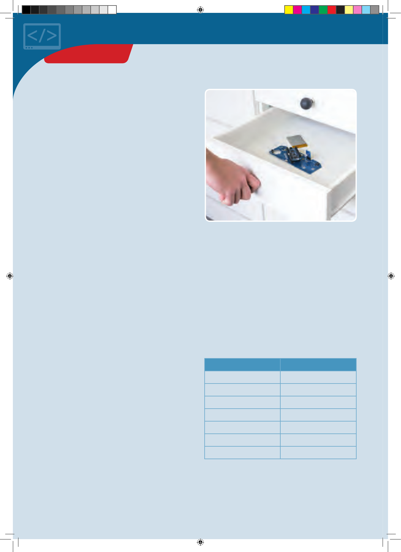
Drawer monitor
Have you ever had the suspicion that your brother or sister
might be secretly looking through your things when you’re
not home? With this drawer monitor, you will be able to
catch them! And the best thing about it is that the
perpetrator won’t even know that the drawer is under
surveillance. There is no alarm, and nothing to indicate to
the culprit that his deed has been noticed. It is only when
you ask the KosmoDuino that you will know whether
someone has been peeking around!
YOU WILL NEED
› KosmoDuino
in the i
nteraction board
› Light sensor
THE PLAN
It’s dark inside a closed drawer, and bright in an open one.
So you can use a light sensor to tell whether your drawer
has been opened or not.
You will be programming your KosmoDuino to do the
following:
1. After it is switched on, it will wait for a push on button 1
to be armed.
2. Once the drawer monitor is armed, it will wait for the
drawer to be closed. That’s when it will start guarding
the drawer.
3. If the drawer is opened again, there are two possibilities
for what will happen then:
a) If the drawer is closed again, it will count as “drawer
was opened.”
b) If you push button 2, the NeoPixel will show you how
often it was opened.
PREPARATION: MEASURING
SENSOR VALUES
To know whether the drawer has been opened or not, you
will be using the light sensor. It measures the brightness of
the light that falls on it. As long as your KosmoDuino is in
the darkness, the reading that it takes will be low. If the
drawer is opened, though, the measurement will rise.
Unfortunately, it is rarely completely dark in any closed
drawer. What level of brightness signals that the drawer
has been opened? Try to find out! Start by inserting your
light sensor into the interaction board. Now you have to
find out how bright it is in daylight. Do that by reading the
sensor and outputting the reading through the serial
monitor. As usual, you will do it with the ReadSensor
sketch on page 33.
Note down the readings output by the sketch when you:
• set the light sensor out under daylight,
• set the light sensor out at dusk,
• cover the sensor completely with your hand,
• shine a flashlight on the sensor.
LIGHT READING
Daylight
Dusk
Shaded
Flashlight
You will need these readings later on when you think
about when the drawer should count as closed.
PROJECT 17
CodeGamer manual inside english.indd 48 7/19/16 12:32 PM
THE MATRIX
In this project, we will be using the NeoPixel and both
buttons. So we will link to the required libraries here.
#include <Adafruit_NeoPixel.h>
#include <KosmoBits_Pins.h>
#include <KosmoBits_Pixel.h>
const int sensorPin = KOSMOBITS_SENSOR_PIN;
const int button1Pin = KOSMOBITS_BUTTON_1_PIN;
const int button2Pin = KOSMOBITS_BUTTON_2_PIN;
int button1 = HIGH;
int button2 = HIGH;
int sensorValue = 0;
enum Mode {IDLE, COUNTDOWN, WAIT_UNTIL_DARK,
CLOSED, OPEN};
Mode mode = IDLE;
const int DARK_VALUE = 100;
unsigned long counter = 0;
KosmoBits_Pixel pixel;
void reset() {
pixel.setColor(0, 0, 0, 0); // Pixel off
mode = IDLE;
counter = 0;
Serial.println("Reset!");
}
</>
We are defining three constants for reading the sensor and
the buttons, as well as the three variables button1 ,
button2 , and sensorValue , which will store the current
measurement readings.
To make sure the program code remains clear, it helps to
think of the program as a machine that can be operated in
various operating modes. Different things happen in the
main loop depending on the mode.
For that purpose, we are using enum Mode to define a so-
called enumeration type: a variable of the Mode type can
only take the values written between the curly brackets —
IDLE , COUNTDOWN , etc.
Next, we define the mode variable in which the current
operating mode is stored. We begin in IDLE mode.
The DARK_VALUE constant specifies the lowest light
sensor reading at which the drawer should start to count
as open. A lot of drawers will let in a little light even when
they are closed. So adjust the value to what makes sense
for yours. The readings that you took in your preliminary
work should help!
The counter variable stores the number of times the
drawer is opened. Finally, pixel gives us access to the
NeoPixel.
When the surveillance is over, we will want to return to
the starting state — as if we had just turned on the
KosmoDuino. For that, we are introducing the r e s e t()
function. The NeoPixel is switched off, mode is set to
IDLE and counter back to 0. As a check, “Reset!” is
output via the serial interface.
PROJECT 17
CodeGamer
CodeGamer manual inside english.indd 49 7/19/16 12:32 PM
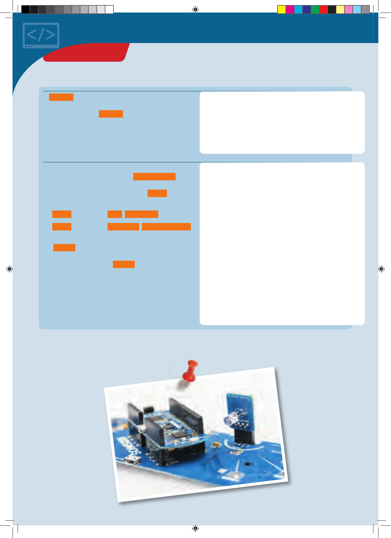
void setup() {
pinMode(sensorPin, INPUT);
pinMode(button1Pin, INPUT);
pinMode(button2Pin, INPUT);
Serial.begin(115200);
reset();
}
void loop() {
sw itch(mod e) {
case IDLE:
loopIdle();
break;
case COUNTDOWN:
loopCountdown();
break;
case WAIT_UNTIL_DARK:
l o o p U n t il D a r k();
break;
case CLOSED:
loopClosed();
break;
case OPEN:
loopOpen();
break;
}
}
</>
In s e t u p () as usual, we determine the operating modes
of the pins being used and initialize the output through the
serial interface. Then, r e s e t () is invoked to return the
drawer monitor to its starting state.
In the main loop, depending on operating mode, different
loop functions may be invoked. The switch(mo d e)
instruction handles that, introducing a case
differentiation. For each case, or possible mode value, a
different function is invoked:
• If mode has the value IDLE , loopIdle() is invoked.
• If mode has the value COUNTDOWN , loopCountdown()
is invoked, etc.
The break; instruction is important here for breaking off
the treatment of a case and ending the case
differentiation. Without the break; instruction, the code
for the next case would also be carried out.
That ends the basic skeleton of our program. Now we will
just have to think about what exactly we want the drawer
monitor to do in its various operating modes.
◀Board with light sensor
PROJECT 17
CodeGamer manual inside english.indd 50 7/19/16 12:33 PM
void loopIdle() {
Serial.println("Idle");
bool pressed = false;
while(digitalRead(button1Pin) == LOW) {
// Button 1 was pressed.
// Wait for it to be released again.
pixel.setColor(0, 255, 0, 25);
pressed = true;
delay(5 0);
}
if (pressed) {
mode = COUNTDOWN;
}
}
void loopCountdown() {
const int COUNTDOWN_NUMBER = 5;
Serial.println("Countdown");
pixel.setColor(0, 0, 0, 0); // Pixel OFF
delay(5 00);
// The actual countdown: Like Blink.
for (int i = 0; i < COUNTDOWN_NUMBER; ++i) {
pixel.setColor(0, 255, 0, 25); // G r e e n
delay(5 00);
pixel.setColor(0, 0, 0, 0); // Pixel off
delay(5 00);
}
pixel.setColor(255, 0, 0, 25); // R e d
delay(1000);
pixel.setColor(0, 0, 0, 0); // Pixel off
mode = WAIT_UNTIL_DARK;
}
</>
By now you probably have a pretty good understanding of
the code. The pressed variable remembers whether the
button was pressed. If button 1 is pressed, the w hil e()
loop is run through: The NeoPixel glows green, and the
pressed variable is set to the true value. When button 1
is released, the w hil e() loop is abandoned. Finally, the
if() instruction tests whether the button was pressed. If
so, the mode is set to COUNTDOWN . Otherwise,
loopIdle() is quit and the main loop is invoked again. It
in turn invokes loopIdle() again, since the mode hasn’t
changed.
IN IDLE
When in its idle state, the drawer monitor is waiting for
button 1 to be pushed before it starts monitoring. What’s
responsible for that is the
loopIdle()
function, which is
invoked by the main loop in
IDLE
mode.
COUNTDOWN
Here, too, you will be familiar with most of the code. First,
the COUNTDOWN_NUMBER determines how many seconds
the countdown should last: 5 seconds, in this case. The
NeoPixel is turned off and after 500 milliseconds the
actual countdown is started in the fo r() loop: 5 times “on
— wait — off.” Then, the NeoPixel is set to “red” for one
second (1000 milliseconds). Finally, the mode is set to
WAIT
_UNTIL_DARK and loopCountdown() is quit.
void loopUntilDark() {
Serial.println("Wait until dark");
while (analogRead(sensorPin) > DARK_VALUE) {
delay(10);
}
mode = CLOSED;
delay(1000);
}
WAIT_UNTIL_DARK
This is easy: It keeps running through the while loop as
long as it’s dark. Measurements are taken every 10
milliseconds. When the w hil e() loop is abandoned, the
mode is set to CLOSED and loopUntilDark() is quit.
PROJECT 17
CodeGamer
CodeGamer manual inside english.indd 51 7/19/16 12:33 PM
void loopClosed() {
Serial.println("In the dark");
sensorValue = analogRead(sensorPin);
if (sensorValue < DARK_VALUE) { // It is
// still dark.
delay(1000); // Wait 1 second, loop() invokes
// this function again.
} else {
// It is bright! Check again
// after 0.5 seconds.
delay(5 00);
if (analogRead(sensorPin) >= DARK_VALUE) {
// It is bright: drawer opened!
mode = OPEN;
}
}
}
void loopOpen() {
Serial.println("Opened");
delay(5 0);
button2 = digitalRead(button2Pin);
sensorValue = analogRead(sensorPin);
if (button2 == LOW) {
output();
} else if (sensorValue < DARK_VALUE) {
// Drawer closed again.
++counter;
mode = CLOSED;
}
}
</>
MONITORING (CLOSED)
The actual monitoring of the drawer happens in CLOSED
mode, i.e. in loopClosed() . First, the current level of
brightness is measured. If it’s dark, it waits one second
(1000 milliseconds). loopClosed() is then invoked once
again from the main loop.
If it’s bright, another reading is performed in 0.5 seconds. If
it’s still bright, it counts as “drawer is open.” The mode is
set to OPEN : In the next pass through the loop, then,
l o o p O P E N () is invoked.
INTRUDERS? (OPEN)
If the drawer has been opened, the drawer monitor still has
to find out if it’s due to an intruder. Maybe, after all, you
opened it yourself. That task is handled by
loopOpen()
.
This function is invoked from the main loop whenever
mode
has the value
OPEN
. We start by checking button 2: If it is
pressed, the monitoring result is output by invoking the
output()
function.
If button 2 is not pressed, the brightness is checked in the
else if part. If it is now dark, the drawer was closed
again. counter is then raised by the value of 1 with
++counter .
If button 2 is not pressed and the drawer has not been
closed again, the function is abandoned and invoked once
again by the main loop.
void output() {
Serial.print("The drawer was opened ");
Serial.print(counter);
Serial.print(" times!\n");
if (counter > 0) {
pixel.setColor(255, 0, 0, 25);
} else {
pixel.setColor(0, 255, 0, 25);
}
delay(2000);
reset();
}
OUTPUT
The output() function is what takes care of the
monitoring result output. First, the exact result is output
via the serial interface. For a quick check without having a
computer connected, though, the result is also output via
the NeoPixel. If the drawer has been opened and then
closed again (i.e., counter > 0 ), the NeoPixel glows red
for 2 seconds. Otherwise, it glows green. Then the monitor
is returned to its starting state with r e s e t () .
PROJECT 17
CodeGamer manual inside english.indd 52 7/19/16 12:33 PM
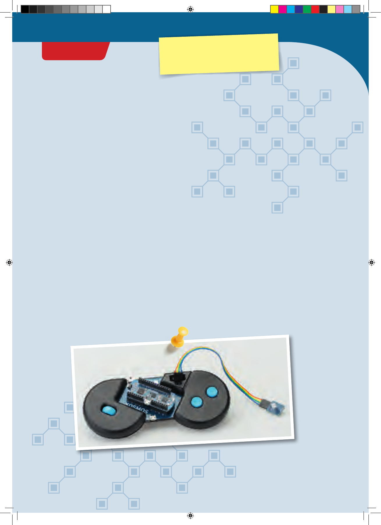
Looking inside the fridge
How can you actually know if the light inside the fridge
really does go out when you close the refrigerator door?
You can’t exactly check just by looking. You would have to
open the door, and then the light would just turn on again.
With your KosmoDuino, though, it’s no problem at all!
YOU WILL NEED
› KosmoDuino in the interaction board
› Light sensor
› Male-female jumper wires
PREPARATION
Remove one strand of 4 wires from the strand of male-
female jumper wires. Insert the plug ends into the socket
that you otherwise stick the KosmoBits sensor module
into.
Then, insert the light sensor into the socket ends of the
wires. Make sure that each of the light sensor pins is
connected via the jumper wire to exactly the right socket
into which it would normally be inserted. In other words,
the wires must not be allowed to cross.
THE PLAN
You will be using the light sensor to measure the
brightness inside the fridge, and you will have the
NeoPixel light up on the interaction board in accordance
with the measured level of brightness.
But how can you have a display outside the fridge for the
brightness on the inside? Easy: You will use extension
wires to hook up the sensor! Then, you will be using the
wires to keep the sensor inside the fridge while
KosmoDuino and its interaction board remain on the
outside.
The wires are so thin that you will still be able to close the
refrigerator door!
PROJECT 18
CodeGamer
Warning! Not suitable for children under 8 years.
There is a risk of hot surfaces of components on the
PCB (printed circuit board) when different polarities
are incorrectly short-circuited or the capacitor is
subject to fault conditions.
CodeGamer manual inside english.indd 53 7/19/16 12:33 PM
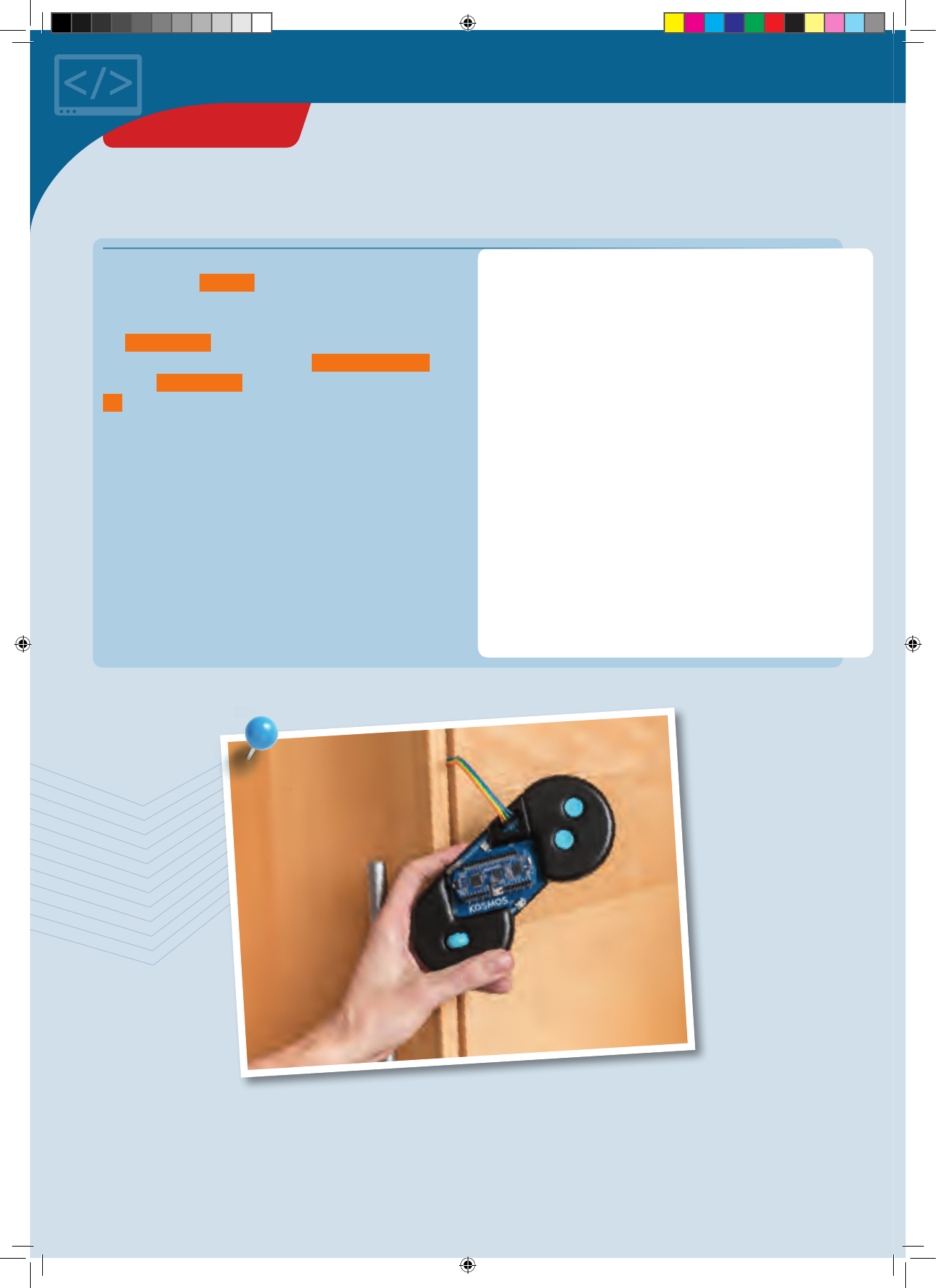
#include <Adafruit_NeoPixel.h>
#include <KosmoBits_Pixel.h>
#include <KosmoBits_Pins.h>
const int sensorPin = KOSMOBITS_SENSOR_PIN;
KosmoBits_Pixel pixel;
void setup() {
pinMode(sensorPin, INPUT);
pixel.setColor(255, 255, 255, 0);
}
void loop() {
int brightness = analogRead(sensorPin);
if (brightness > 255) {
brightness = 255;
}
pixel.setColor(255, 255, 255, brightness);
delay(10);
}
You can probably understand the program without any
help. In brief: In s e t u p () you set the sensor pin mode and
switch off the NeoPixel. In the main loop, you use the light
sensor to measure the brightness and store the reading in
the brightness variable. Since the brightness value
must not be greater than 255 with pixel.setColor() ,
limit the brightness value to 255 with the help of the
if instruction.
Now you just need to place the sensor in the fridge and
close the door. And what’s the answer? Does the light go
out?
</>
THE PROGRAM
▲Jumper wire in fridge
PROJECT 18
CodeGamer manual inside english.indd 54 7/19/16 12:33 PM
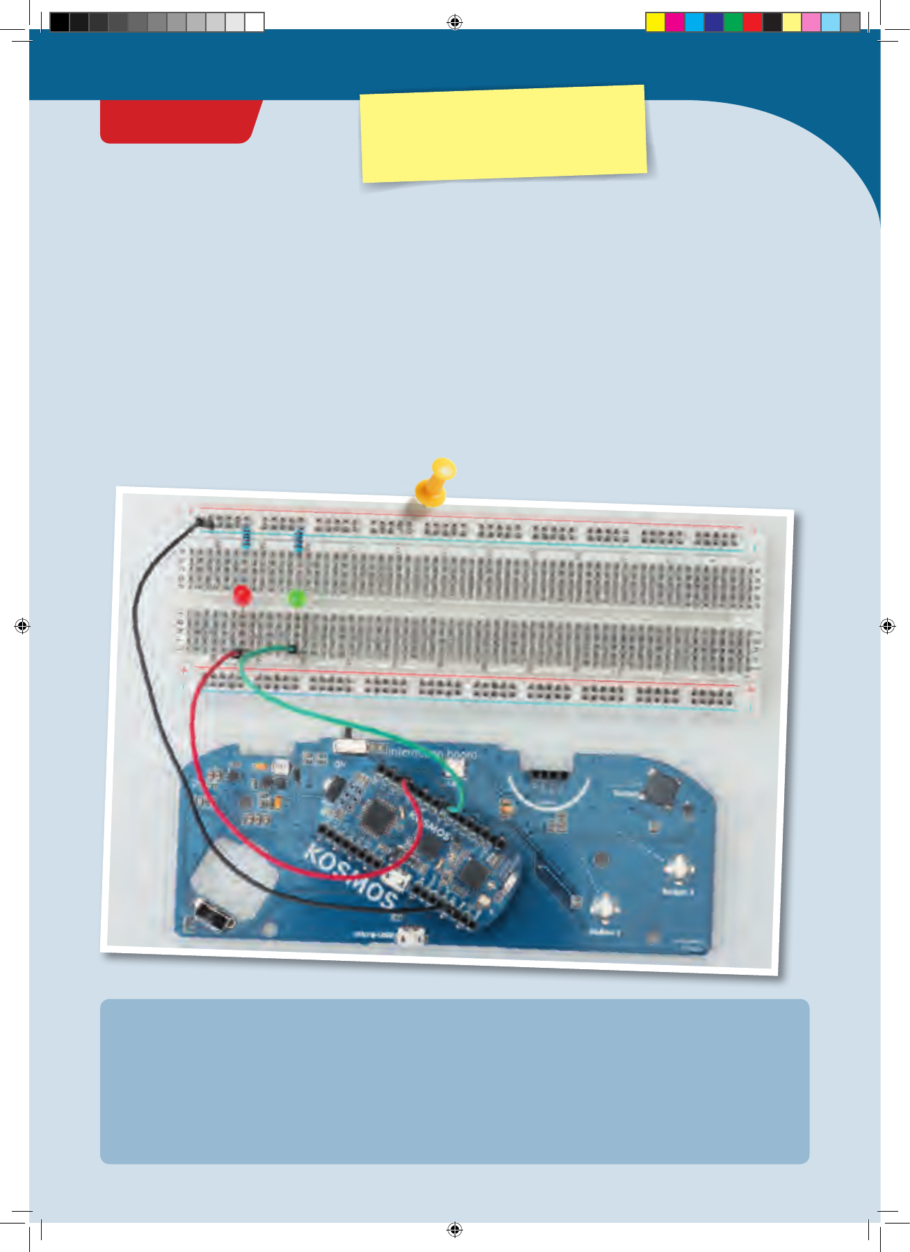
Ghostly eyes
How would you like to turn your jack-o’-lantern into
something even spookier this Halloween? With your
KosmoDuino, you will be able to give it ghostly eyes.
YOU WILL NEED
› KosmoDuino in the interaction board
› Resistors
› Green LED
› Red LED
› Male-male jumper wires
› Male-female jumper wires
› Breadboard
THE PLAN
Make your jack-o’-lantern’s eyes blink colorfully. On top
of that, you can have it make a gruesome hissing noise at
irregular intervals.
PREPARATION
This time, you will need more than just the interaction
board, because you will have to build a small electronic
circuit. Assemble it out of the parts listed on the left,
following the illustration.
Be careful to get the polarity of the LEDs correct! They
only work in one direction. Pay attention to the orientation
of their long and short legs.
• One jumper wire connects one GND pin with the
(–) strip of the breadboard.
• One jumper wire connects pin 11 of the KosmoDuino
with hole j 57 of the breadboard.
• One jumper wire connects pin 6 of the KosmoDuino
with hole j 51 of the breadboard.
• The resistors connect the (–) strip and hole a 57 along
with the (–) strip and hole a 51.
• The long leg of the red LED is inserted in hole f 57, the
short one in e 57. Place the short leg of the green LED
in hole f 51 and the long leg in hole e 57.
• To guide the LEDs from the breadboard to the jack-o’-
lantern’s eyes, use the 4 male-female jumper wires to
connect the correspondingly positioned LEDs with the
breadboard.
IN THIS EXAMPLE, THE ASSEMBLY GOES AS FOLLOWS:
CodeGamer
PROJECT 19
Warning! Not suitable for children under 8 years.
There is a risk of hot surfaces of components on the
PCB (printed circuit board) when different polarities
are incorrectly short-circuited or the capacitor is
subject to fault conditions.
CodeGamer manual inside english.indd 55 7/19/16 12:33 PM
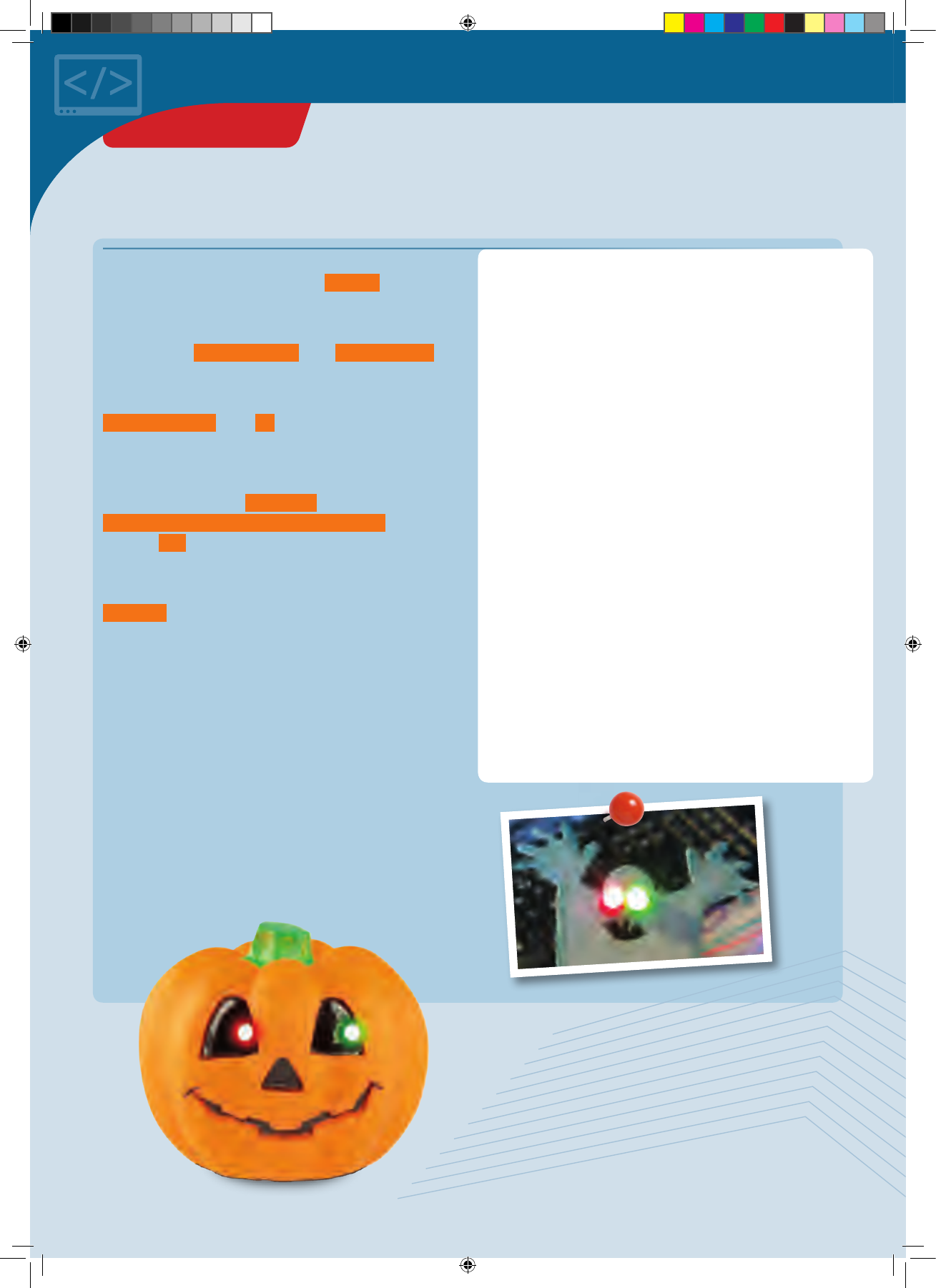
#include <KosmoBits_Pins.h>
const int buzzerPin = KOSMOBITS_BUZZER_PIN;
const int redPin = 11;
const int greenPin = 6;
void setup() {
randomSeed(analogRead(3));
pinMode(redPin, OUTPUT);
pinMode(greenPin, OUTPUT);
}
void loop() {
// Blinking
analogWrite(redPin, random(0, 256));
analogWrite(greenPin, random(0, 256));
delay(200);
// His si n g
if (random(0, 1000) > 900) {
for (int i = 0; i < 3000; ++i) {
analogWrite(buzzerPin, random(0, 256));
}
}
}
The program is extremely simple. First, the constants are
defined for the pins you are using. In s e t u p () , we will
give a starting value to the random generator.
In the main loop, the brightness of each LED is first set to a
random value, random(0, 256) , with a n al o g W r it e() .
That will produce the flickering of the ghostly eyes.
To produce the hissing noise, you will use
ra n do m(0, 1000) in the if statement to create another
random number — this time between 0 (smallest possible
value) and 999 (greatest possible value).
If the random number is greater than 900, write 3000
random values into the buzzerPin with
analogWrite(buzzerPin, random(0, 256)); in the
adjacent for loop. That will produce the hissing sound in
the speaker.
The random numbers to be produced with the help of the
random() function are evenly distributed. That means
that every possible number will occur just as often as any
other over a long period of time. The hissing will only be
output, however, when the random number is greater than
900. That happens about one tenth of the time. If you want
the hissing to happen less often, just choose a number
larger than 900.
Now you can install these ghostly flickering eyes in a
jack-o’-lantern or a homemade ghost.
The ghostly eyes can be combined with lots of other
excellent ideas. How about a siren than howls when you
shine a flashlight on the jack-o’-lantern? You have already
learned how to do that. No doubt, you will also have a lot
of other great ideas of your own!
</>
THE PROGRAM
▲Ghostly eyes
PROJECT 19
CodeGamer manual inside english.indd 56 7/19/16 12:33 PM
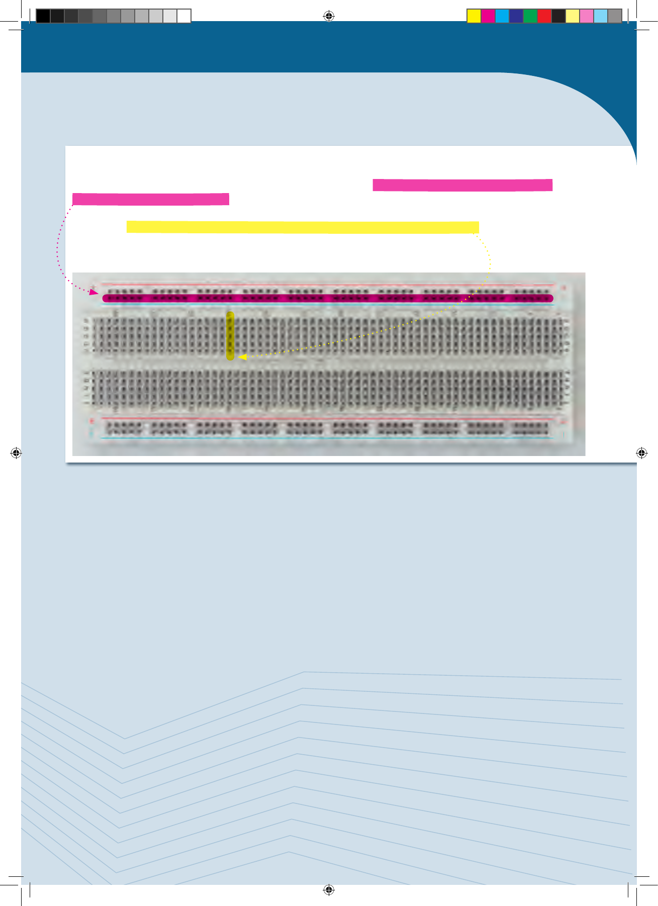
!
BREADBOARD
The breadboard gives you an easy way to assemble electronic circuits. The outer red- and blue-marked rows are
electrically connected to each other. This is where you usually connect the power supply. To do that, you connect one of
the microcontroller pins marked with “GND” (for “ground”) with a (-) hole and one “5V” pin with a (+) hole in the
breadboard. The vertical columns (a to e and f to j) are also electrically connected to each other — although only up to
the “ditch” in the middle of the board. You can see all these details in the illustration.
Where does it go from here?
You have now acquired a solid foundation in Arduino programming. You can and should build on it. The CodeGamer kit
and the KosmoBits system give you a good start, because in addition to the actual microcontroller you already have a
breadboard, some LEDs, jumper wires and, of course, sensors. With the help of the battery, you will even be able to
operate the entire setup independently of a computer and without any extra parts. The battery has a pretty high
capacity. You will notice that by the fact that it rarely needs to be recharged. In short: You are well equipped!
You will find a lot of other project ideas on the Internet. Every once in a while, you will probably need an extra electronic
component for one of those projects. You already have the rest though. Most important, you have even learned how to
program by writing real code!
Now let your imagination run wild!
CodeGamer
CodeGamer manual inside english.indd 57 7/19/16 12:33 PM
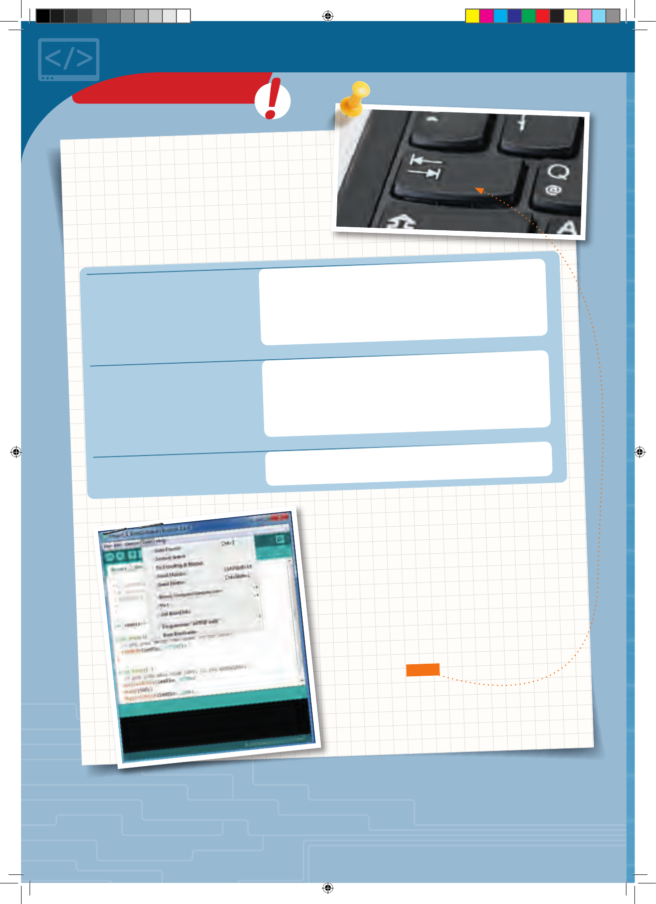
Let’s take a simple example:
It could be written as follows:
Or — even worse — as follows:
if (digitalRead(button1) == LOW) {
red = 255;
} else {
red = 0;
}
if (digitalRead(button1) == LOW) {
red = 255;
} else {
red = 0;
}
if (digitalRead(button1) == LOW) {red = 255;} else
{red = 0;}
Indented
You may have wondered why a lot of the lines found in
the programming text are indented, or moved a little to
the right compared to the others. The reason for it is
simple: It makes the programming text easier to read.
All these versions mean the same thing, it’s just the
formatting that changes. And yet, in the first example
you can see the structure of the program at a glance. It
is easier to read the code.
That is why it makes sense to indent the program code
whenever it begins a new block. Also, as a rule, each
individual instruction should get its own line.
The Arduino environment will help you with this, and
usually moves new blocks to the right all by itself. If
you ever want to indent portions of text by hand,
though, use the tab key rather than the space key.
◀Automatic formatting
KNOWLEDGE BASE
CodeGamer manual inside english.indd 58 7/19/16 12:33 PM
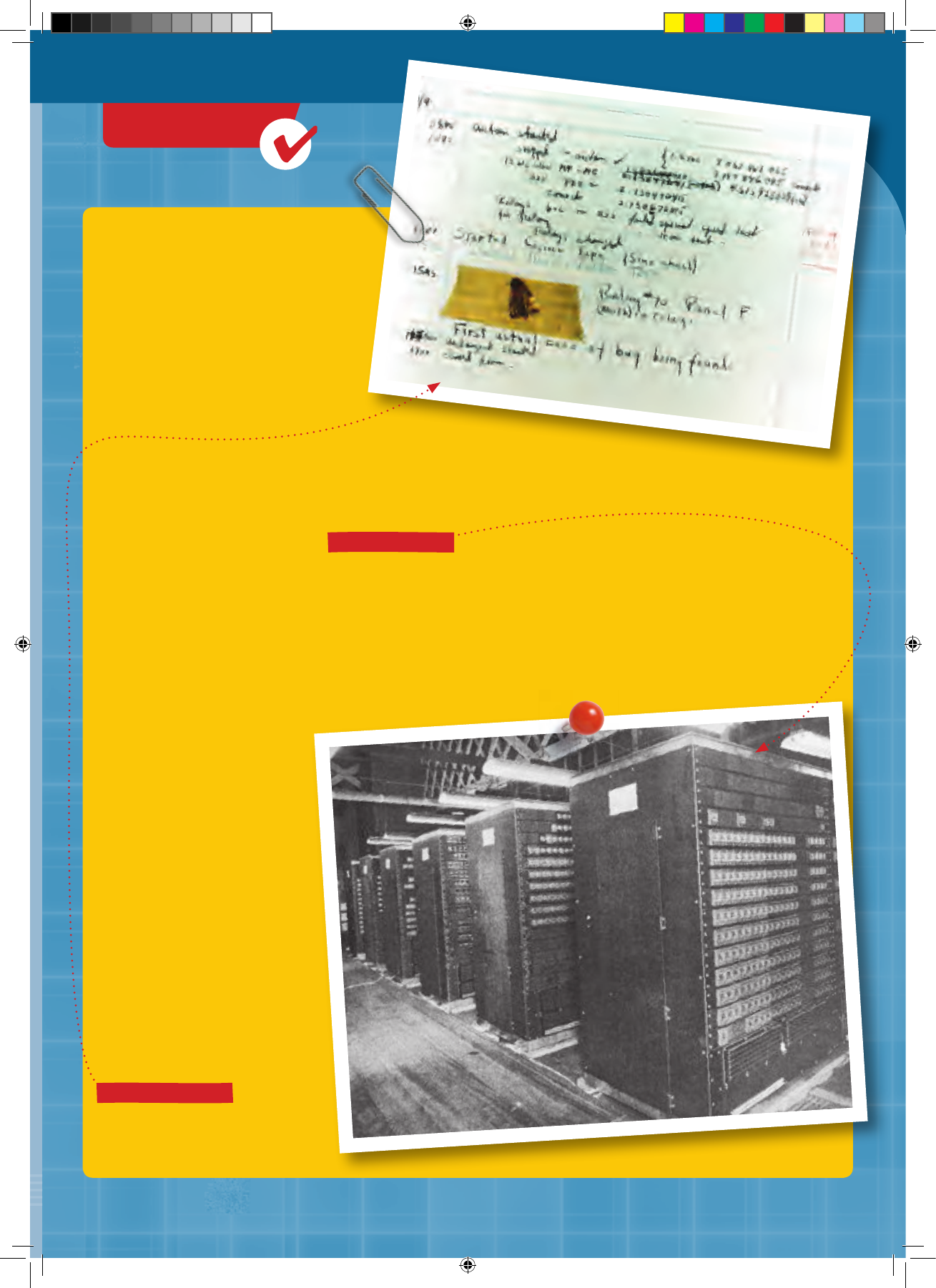
CHECK IT OUT
CodeGamer
▲The logbook page with moth
▲Harvard Mark II
What is
a bug,
anyway?
When a program doesn’t do what it’s supposed to do, the error is called a bug. You can just call it
an error, but the term bug is used much more often. There’s an amazing story behind this term!
Earlier computers, such as the Harvard Mark II, completed in 1947, did not yet have any
microprocessors. Instead, they performed calculations with the help of electromechanical relays.
A relay basically consists of an electromagnet and a magnetically activated switch. If the
electromagnet is turned on, it activates the switch. If the magnet is turned on again, it moves the
switch back to the “off” setting. The important thing is that this kind of relay involves the actual
movement of something, namely the switch.
On September 9, 1947, the
technicians responsible for
the Mark II were looking
for the source of an error.
They found it: There was a
moth that had wedged
itself into a relay! The first
bug in a computer program,
in other words, literally was
an insect. The moth,
meanwhile, was dutifully
taped into the
Mark II logbook.
CodeGamer manual inside english.indd 59 7/19/16 12:33 PM
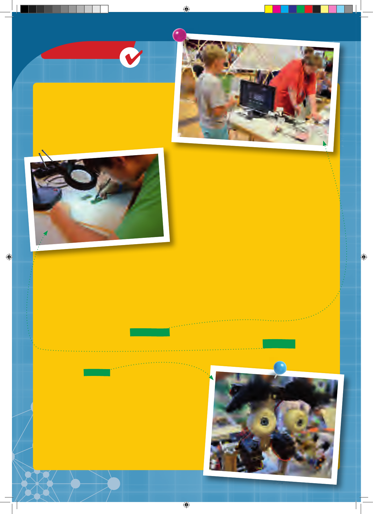
Maker project ▶
▲Workshop at a Maker Faire
CHECK IT OUT
Arduino and
the Maker
Have you ever dreamed of being an inventor? Of
thinking up new machines and gadgets and turning
them into reality? More and more people are moving
beyond merely dreaming, and deciding to actually
do it. They are makers!
Makers used to be called tinkerers or hobbyists. But
those words aren’t quite right anymore. While most
tinkerers used to like to keep themselves busy all
alone in their own workshops, makers also like to come out into the open and share their projects.
So a lot of hackerspaces or makerspaces have been created in cities around the world. These are
like a cross between a meeting place and a community workshop. They are places where the
makers can compare notes, present their latest ideas, give each other advice, and have access to
shared parts and tools.
There are also more and more Maker Faires popping up around the world, which allow makers to
present themselves to a larger public. They also typically offer an array of workshops for
experienced makers to add to their knowledge and for beginners to take their first steps.
In the makers’ projects, microcontrollers such as the
one from Arduino often play an important role. They
are what makes it possible to create complex gadgets
without first having to develop expensive specialized
electronics.
At a Maker Faire ▶
CodeGamer manual inside english.indd 60 7/19/16 12:33 PM
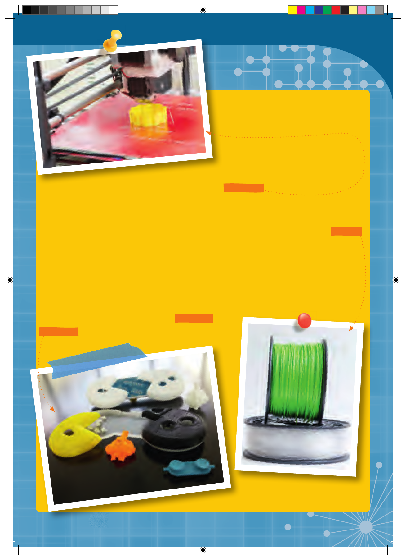
3D Printers
What good will the best electronics
and the greatest software do you
if you can’t find an appropriate housing for your
project? This is where a recent maker solution comes in: 3D printers.
These are devices that are capable of printing out three-dimensional (3D) objects rather than just
two-dimensional (2D) images on paper. It may sound like science fiction, but it’s very simple in
principle. You typically start with a plastic material rolled up like thread on a spool. This filament
is then heated to the melting point in a nozzle. In molten form, the plastic is computer-guided to a
certain location and then squirted out. The plastic then cools and hardens. Drop by drop, layer by
layer, even complicated and intricate structures can be built in this way.
Devices capable of doing this kind of thing have existed for a while, but it is only in the last few
years that they have become affordable for hobbyists.
By the way: The first test versions of the KosmoBits
controller were created in this way too!
CodeGamer
◀A 3D printer at work
◀Various 3D-printed prototypes from the CodeGamer development stages
▲Filament for a 3D Printer
CodeGamer manual inside english.indd 61 7/19/16 12:33 PM
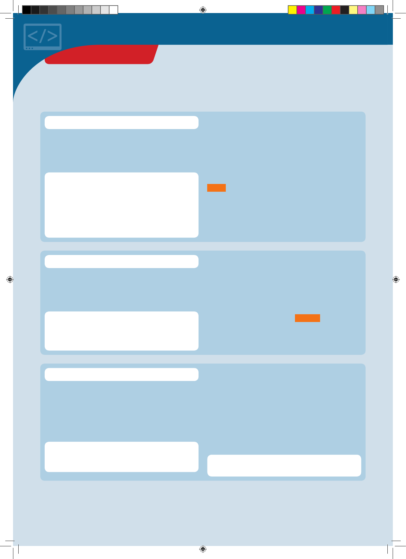
Common Error Messages
Here, a semicolon was expected before the closing
parenthesis, but it was not found.
A name used in the program is not familiar to the computer.
This is often an indication of a simple typo.
A type used in the program is not familiar to the compiler.
In most cases, this either involves a typo or you forgot to
include the corresponding file.
error: expected ';' before ')'
error: '...' was not declared in this scope
error: '...' does not name a type
EXAMPLE:
EXAMPLE:
EXAMPLE:
In function 'int average2()':
DoubleClap:86: error: expected ';' before
')' t o k e n
for (int i = 0; i < N, ++i) {
^
exit status 1
expected ';' before ')' token
error: 'pinnMode' was not declared in this
scope
pinn M ode(A1, INP UT);
error: 'KosmoBits_Pixel' does not name a
type
KosmoBits_Pixel pixel; #include <Adafruit_NeoPixel.h>
#include <KosmoBits_Pixel.h>
SOLUTION:
SOLUTION:
SOLUTION:
The comma has to be replaced with a semicolon after
i < N .
Correct typo: It is actually called pinMode .
Include “KosmoBit_Pixel.h”:
ERROR MESSAGES
CodeGamer manual inside english.indd 62 7/19/16 12:33 PM

You presumably forgot to close the serial monitor before
trying to upload the program.
1. You forgot to connect the KosmoDuino to the computer.
You might also have inserted the USB cable into the
interaction board’s charge socket by mistake.
2. The wrong port has been set. Check Tools ➜ Port and
change the port if necessary.
avrdude: ser_open(): can't open device "\\.\COM4": Access is denied.
avrdude: ser_open(): can't open device "\\.\COM4": The system cannot
find the file specified.
Low memory available, stability problems may occur.
EXAMPLE:
int array[1000] = {}; // That is too large!
SOLUTION:
SOLUTION:
SOLUTION:
SOLUTION:
Change your program by using a smaller array.
Close the serial monitor and re-upload the program.
Use the USB cable to connect your computer to the
KosmoDuino via the USB port.
Select a different port.
Your program is using almost all the microcontroller’s
RAM or is even too large for it. You may have applied a
large array.
Not enough memory.
CodeGamer
CodeGamer manual inside english.indd 63 7/19/16 12:33 PM
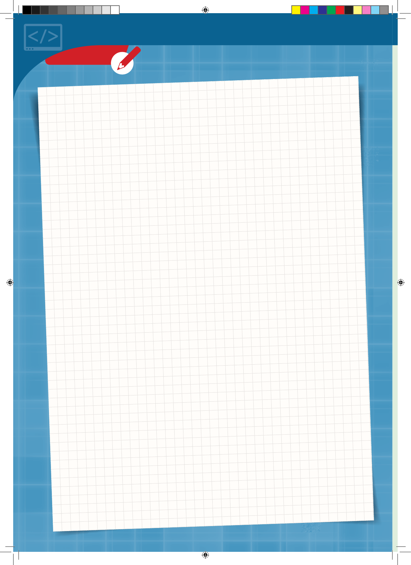
NOTES
CodeGamer manual inside english.indd 64 7/19/16 12:33 PM