TOA S404HDX Wireless Handheld Microphone User Manual S4 system e
TOA Corporation Wireless Handheld Microphone S4 system e
UserManual.wiki
>
TOA
>
S404HDX User Manual
User Manual
Navigation menu
Upload a User Manual
Namespaces
Wiki Guide
HTML
PDF
Info
Views
User Manual
Discussion / Help
Navigation
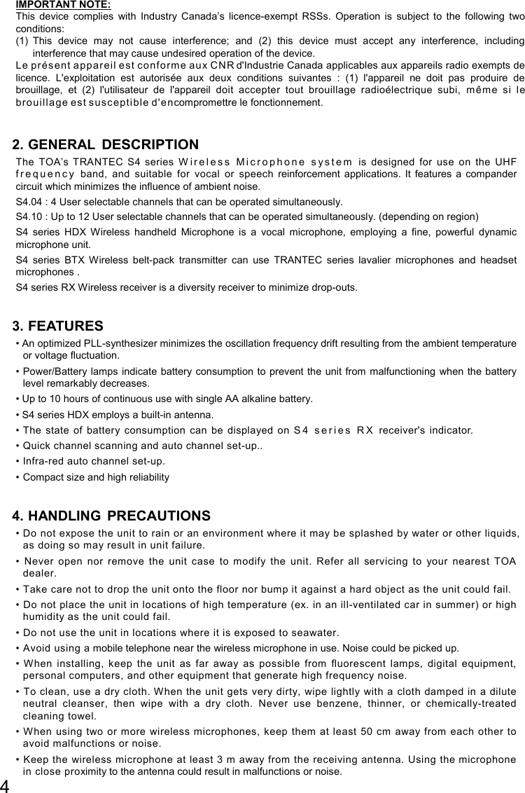
![5 5. NOMENCLATURE AND FUNCTIONS Receiver : S4.04-RX & S4.10-RXA [Front]1. Power switch Press this switch to turn the power on, and press it again to turn off the power. 2. Channel setting key [SET] Used to select the receiving channel (frequency). (The receiver frequency must be identical to that of the microphone.) 3. Infrared (IR) sync key [SYNC] Press this switch to transfer the frequency to the transmitter. 4. Reception lamps [A, B] Either lamp of A (left) or B (right) lights yellow when the receiver matches a radio signal from the transmitter. 5. AF peak lamp [PEAK] Lights red when the receiver output level reaches the point about 3 dB below the clipping level. 6. Infrared (IR) port [IR] Transmit the infrared signal, when pressing SYNC key, 7. Numerical LED display Indicates the current channel number in normal state. In setting mode, the indicated channel number flashes until registered. 8. RF signal level meter (S4.10-RXA only) Indicates the current channel number in normal state. 9. Antennas (S4.04-RX only) Raise both antennas at 45° outwards from a vertical line. When carrying the unit, be sure to fold down both antennas to prevent them from break. S4.04-RX S4.10-RXA](https://usermanual.wiki/TOA/S404HDX/User-Guide-3071038-Page-5.png)
![6 [Rear] 10. DC input jack Connect the power cable of the supplied AC adapter to this jack. 11. Cable hanger Hook the power cable onto this part. 12. AF output Balanced XLR jack, male type (Pin #2: Hot). S4.04-RX : -20 dBu (maximum) S4.10-RXA : 16 dBu (maximum) 13. AF output Unbalanced phone jack S4.04-RX and S4.10-RXA : 10 dBu (maximum) 14. Volume control (S4.10-RXA only) Adjust the output level. 15. Antenna input A, B (S4.10-RXA only) BNC connectors for antennas Phantom powering for the external antenna (optional) For the wireless system covering a relatively narrow area, use the supplied two rod antennas, which should be set up at 45° outwards from a vertical line. Tip S4.10-RXA receiver gain is continuously adjustable. Should the receiver signal be too high, it will distort your mixer / amplifier. If the signal is too low, the result will be an increase in general background noise. Monitor the AF peak LED on the receiver, and adjust the volume control to achieve the best signal quality. S4.04-RX S4.10-RXA](https://usermanual.wiki/TOA/S404HDX/User-Guide-3071038-Page-6.png)
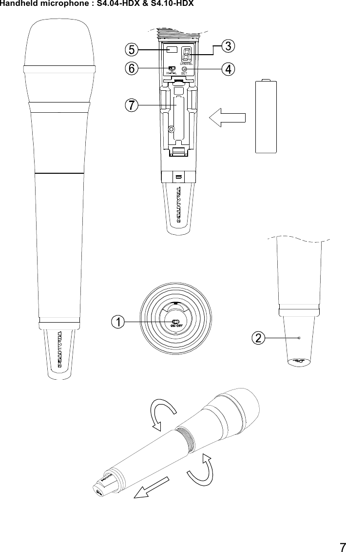
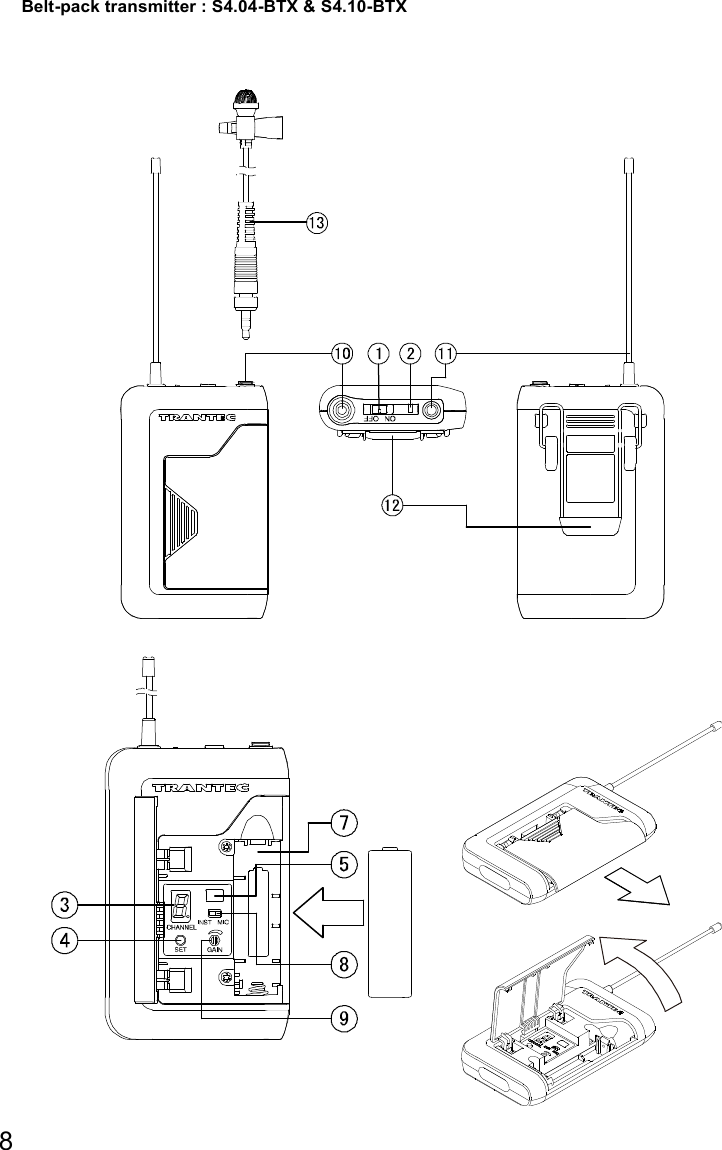
![9 1. Power switch Slide this switch towards “ON” to turn the power on, and slide it again towards “OFF” to turn off the power. 2. Power / Battery lamp A green LED lights as long as the battery capacity is sufficient. When the battery capacity becomes low, the green LED starts to flash. 3. Numerical LED display Indicates the current channel number in normal state. In setting mode, the indicated channel number flashes until registered. 4. Channel setting key [SET] Used to select the channel (frequency). (The frequency must be identical to that of the receiver.) 5. Infrared (IR) port Receive the infrared signal from the receiver. 6. PAD switch (S-4.10-HDX only) This switch is used for microphone sensitivity adjustment .The sensitivity can be decreased by “H” (0dB), “L” (-10dB). Note Never position the transmitter antenna directly against the body or hand. This will have the effect of reducing the operating range considerably. 7. Battery compartment Insert an AA battery according to (+ ) and (–) indications on the battery compartment. Note: Turn off the power switch. HDX: Hold the microphone body and rotate the microphone grip counterclockwise to remove it. BTX: Slide the battery cover in the direction indicated by the arrow while pressing on the cover with a thumb and hinge up-wards. 8. MIC / Instrument switch (BTX only) Slide this switch towards “MIC” to connect the microphone, and slide it towards “INST” to connect the instrument. 9. Audio level control (BTX only) Adjust the audio level control using the suppli ed screwdriver. The transmitter sensitivity increases as the control is rotated clockwise, and decreases as rotated counterclockwise. 10. Input connector (BTX only) 3.5 mm j ack socket, Connect the microphone or the instrument cable. 11. Antenna (BTX only) 12. Clip (BTX only) Clip the transmitter to a belt through the transmitter clip. It is better the belt should be pressed against the base of the transmitter clip. 13. Microphone (BTX only) Note: Route the microphone cable so as to avoid undue strain of friction. Try and keep the microphone cable away from the antenna. 6. CHANNEL NUMBER SETTING by MANUAL Step 1. Press the SET key for about 3 seconds until the displayed channel number blinks. Step 2. Select the desired channel number with the SET key, and once the desired number is reached, release the SET key. After about 5 seconds, the receiver automatically sets channel and the blinking number turns to steady light. Tip Continuous or each depression of the SET key permits the display to cycle through the channel numbers. On the receiver side, when the dot LED by the channel number LED is blinking at selecting channel number, this means that the channel has already been occupied. Note Make sure that the transmitter is identical to the receiver in the channel number. Should the microphone's setting differ from that of the receiver, the receiver does not receive the radio signal from the transmitter. On the transmitter side, the power switch turns on, the channel number display turns on the light for about 30 seconds, and then this display turns off the light. When SET key presses in this condition, this display turns on the light for about 30 seconds.](https://usermanual.wiki/TOA/S404HDX/User-Guide-3071038-Page-9.png)
![11 10. OPERATIONAL HINTS • The transmitter's service distance is 3 – 100 m. When the transmitter user moves in a facility, signal dropouts (momentary losses of signal reception) may be encountered. These dropouts are caused by the building's architectural designs or materials which block the travel of or reflect the radio signal. If this occurs, the user needs to change locations for better signal reception. • Confirm the good line of sight between the transmitter and the receiver. Do not place the large obstructions (ex. Concrete walls or large metal obstructions) between the transmitter and the receiver. In addition keep the receiver away from the metallic beams and obstructions as these can adversely affect the antenna pick-up pattern and induce the interference. • The proper operation of your wireless system may be interfered with by other system operating on the same frequency. In such cases, change the operating frequency of your system. • Hold the microphone within 20cm from the sound source. Move the microphone closer for a warmer sound increased. And do not cover the grille with hand. • Keep your mouth 15 – 20 cm away from the lavalier microphone for the best possible sound reproduction. In case of the Omni-directional response, it will pick up sounds from all directions. It is better that the microphone is placed closer to the sound source. Take care not to bring your mouth too close to the microphone (within 5 cm) as this impairs speech clarity if you speak loudly. • In case of the headset microphone, by adjusting the gooseneck, locate the microphone with the supplied windscreen in front of your mouth, and position it 3 – 5 cm away from your mouth for the best sound reproduction. When the microphone is too close to your mouth or you speak too loud, speech clarity will be impaired, making it hard for the audience to hear announcements. 11. TROUBLESHOOTING Issue Condition Solution No sound Receiver Reception lamps [either A or B] or RF signal level meter lights. Confirm the connections of all sound system or gain Confirm the receiver volume control. Sound distorted AF peak lamp [PEAK] indicates. Confirm the transmitter gain or PAD. Confirm the receiver volume control. Confirm the receiver output level match to the input level of the mixer / amplifier. Poor range or sound dropouts Receiver Reception lamps [A and B] are flicking or RF signal level meter turn light off.. The system must be set up within recommended range. The transmitter must be used in line of sight from the receiver. Check the channel scan, confirm nearby source of interference, and change the receiver and the transmitter to a different channel. Confirm the battery indication, and replace the transmitter battery.](https://usermanual.wiki/TOA/S404HDX/User-Guide-3071038-Page-11.png)