TOA S404HDX Wireless Handheld Microphone User Manual S4 system e
TOA Corporation Wireless Handheld Microphone S4 system e
TOA >
User Manual
OPERATING
INSTRUCTIONS
WIRELESS MICROPHONES SYSTEM
S4.04 / S4.10 series
CONTENTS
1. SAFETY PRECAUTIONS
2. GENERAL DESCRIPTION
3. FEATURES
4. HANDLING PRECAUTIONS
5. NOMENCLATURE AND FUNCTIONS
6. CHANNEL NUMBER SETTING by MANUAL
7. CHANNEL NUMBER SETTING by
INFRARED SYNCHRONIZATION
8. CHANNEL SCAN
9. BATTERY ALARM
10. OPERATIONAL HINTS
11. TROUBLESHOOTING
12. SPECIFICATIONS
13. FREQUENCY TABLE
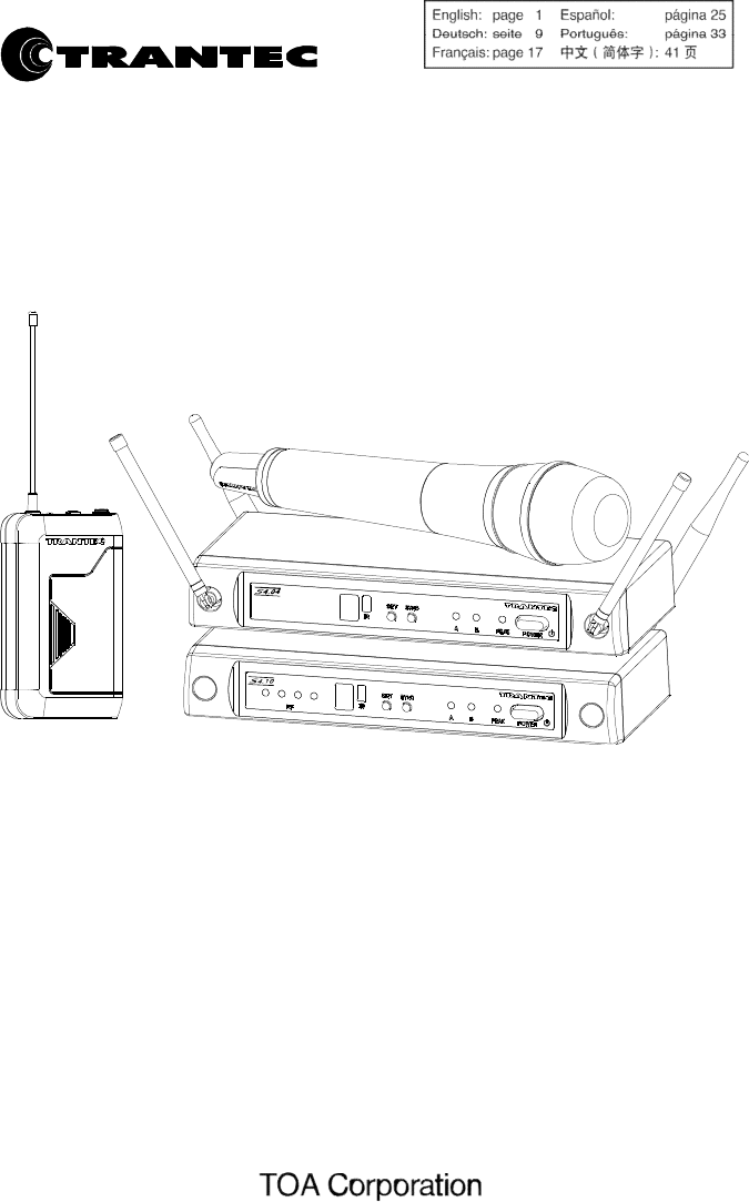
Thank you for purchasing TOA's TRANTEC S4 series Wireless Microphone system.
Please carefully follow the instructions in this manual to ensure long, trouble-free use of your equipment.

2
1. SAFETY
PRECAUTIONS
• Be sure to read the instructions in this section carefully before use.
• Make sure to observe the instructions in this manual as the conventions of safety symbols and messages
regarded as very important precautions are included.
• We also recommend you keep this instruction manual handy for future reference.
Safety Symbol and Message
Conventions
Safety symbols and messages described below are used in this manual to prevent bodily injury and property
damage which could result from mishandling. Before operating your product, read this manual first and
understand the safety symbols and messages so you are thoroughly aware of the potential safety hazards.
WARNING
Indicates a potentially hazardous situation which, if mishandled, could
result in death or serious personal injury.
When Installing the Receiver
• Do not expose the unit to rain or an environment where it may be splashed by water or other liquids, as
doing so may result in fire or electric shock.
• Use the unit only with the voltage specified on the unit. Using a voltage higher than that which is specified
may result in fire or electric shock.
• Do not cut, kink, otherwise damage nor modify the power supply cord. In addition, avoid using the power
cord in close proximity to heaters, and never place heavy objects -- including the unit itself -- on the power
cord, as doing so may result in fire or electric shock.
• Avoid installing or mounting the unit in unstable locations, such as on a rickety table or a slanted surface.
Doing so may result in the unit falling down and causing personal injury and/or property damage.
• To prevent lightning strikes, install the unit at least five meters away from a lightning rod, and yet within the
protective range (angle of 45°) of the lightning conductor. Lightning strikes may cause a fire, electric shock
or personal injury.
• Since the unit is designed for in-door use, do not install it outdoors. If installed outdoors, the aging of parts
causes the unit to fall off, resulting in personal injury. Also, when it gets wet with rain, there is a danger of
electric shock.
When the Receiver is in Use
• Should the following irregularity be found during use, immediately switch off the power, disconnect the power
supply plug from the AC outlet and contact your nearest TOA dealer. Make no further attempt to operate the
unit in this condition as this may cause fire or electric shock.
· If you detect smoke or a strange smell coming from the unit.
· If water or any metallic object gets into the unit
· If the unit falls, or the unit case breaks
· If the power supply cord is damaged (exposure of the core, disconnection, etc.)
· If it is malfunctioning (no tone sounds.)
• Do not place cups, bowls, or other containers of liquid or metallic objects on top of the unit. If they
accidentally spill into the unit, this may cause a fire or electric shock.
• Do not touch the unit's antennas during thunder and lightning, as this may result in electric shock.
When the Microphone or the Transmitter is in Use
• To prevent the electromagnetic wave from badly influencing medical equipment, make sure to switch
off the unit's power when placing it in close proximity to the medical equipment

3
CAUTION
Indicates a potentially hazardous situation which, if mishandled,
could result in moderate or minor personal injury, and/or property
damage.
When Installing the Receiver
• Never plug in nor remove the power supply plug with wet hands, as doing so may cause electric shock.
• When unplugging the power supply cord, be sure to grasp the power supply plug; never pull on the cord
itself. Operating the unit with a damaged power supply cord may cause a fire or electric shock.
• When moving the unit, be sure to remove its power supply cord from the wall outlet. Moving the unit with the
power cord connected to the outlet may cause damage to the power cord, resulting in fire or electric shock.
When removing the power cord, be sure to hold its plug to pull.
• The socket outlet shall be installed near the equipment and shall be easily accessible.
• Avoid installing the unit in humid or dusty locations, in locations exposed to the direct sunlight, near the
heaters, or in locations generating sooty smoke or steam as doing otherwise may result in fire or electric
shock.
When the Receiver is in Use
• Do not place heavy objects on the unit as this may cause it to fall or break which may result in personal injury
and/or property damage. In addition, the object itself may fall off and cause injury and/or damage.
• Make sure that the volume control is set to minimum position before power is switched on. Loud noise
produced at high volume when power is switched on can impair hearing.
• Never open the unit case as there are high temperature parts inside the unit, which may cause a burn if
touched. Refer all servicing to your nearest TOA dealer.
• Use the dedicated AC adapter for the unit. Note that the use of other adapter may cause a fire.
• If dust accumulates on the power supply plug or in the wall AC outlet, a fire may result. Clean it periodically.
In addition, insert the plug in the wall outlet securely.
• Switch off the power, and unplug the power supply plug from the AC outlet for safety purposes when cleaning
or leaving the unit unused for 10 days or more. A fire or electric shock may result.
• Any modifications made to this device that are not approved by TOA Corporation may void the authority
granted to the user to operate this equipment.
• Operation of this device is subject to the following two conditions: (1) this device may not cause interference,
and (2) this device must accept any interference, including interference that may cause undesired operation
of the device.
When the Microphone or the Transmitter is in Use
• When the unit is not in use for 10 days or more, be sure to take the battery out of the unit because battery
leakage may cause personal injury or contamination of environment.
• Make sure to observe the following handling precautions so that a fire or personal injury does not result from
leakage or explosion of the battery.
· Do not short, disassemble heat nor put the battery into a fire.
· Do not solder a battery directly.
· Be sure to use the specified type of battery
· Note correct polarity (positive and negative orientation) when inserting a battery in the unit.
· Avoid locations exposed to the direct sunlight, high temperature and high humidity when storing batteries.
• When the battery becomes inflated or leaks, discontinue use and replace with new one immediately
CAUTION TO USER: Changes or modifications not expressly approved by the party responsible for
compliance could void the user's authority to operate the equipment.
IMPORTANT NOTE: To comply with the FCC RF exposure compliance requirements, no change to the
antenna or the device is permitted. Any change to the antenna or the device could result in the device
exceeding the RF exposure requirements and void user’s authority to operate the device.

4
IMPORTANT NOTE:
This device complies with Industry Canada’s licence-exempt RSSs. Operation is subject to the following two
conditions:
(1) This device may not cause interference; and (2) this device must accept any interference, including
interference that may cause undesired operation of the device.
Le pr és ent a pp ar ei l est co nfo rm e aux CNR d'Industrie Canada applicables aux appareils radio exempts de
licence. L'exploitation est autorisée aux deux conditions suivantes : (1) l'appareil ne doit pas produire de
brouillage, et (2) l'utilisateur de l'appareil doit accepter tout brouillage radioélectrique subi, m êm e si le
brouilla ge est susc epti ble d'e n compromettre le fonctionnement.
2. GENERAL
DESCRIPTION
The TOA’s TRANTEC S4 series W i r e l e s s M i c r o p h o n e s y s t e m is designed for use on the UHF
f r e q u e n c y band, and suitable for vocal or speech reinforcement applications. It features a compander
circuit which minimizes the influence of ambient noise.
S4.04 : 4 User selectable channels that can be operated simultaneously.
S4.10 : Up to 12 User selectable channels that can be operated simultaneously. (depending on region)
S4 series HDX Wireless handheld Microphone is a vocal microphone, employing a fine, powerful dynamic
microphone unit.
S4 series BTX Wireless belt-pack transmitter can use TRANTEC series lavalier microphones and headset
microphones .
S4 series RX Wireless receiver is a diversity receiver to minimize drop-outs.
3.
FEATURES
• An optimized PLL-synthesizer minimizes the oscillation frequency drift resulting from the ambient temperature
or voltage fluctuation.
• Power/Battery lamps indicate battery consumption to prevent the unit from malfunctioning when the battery
level remarkably decreases.
• Up to 10 hours of continuous use with single AA alkaline battery.
• S4 series HDX employs a built-in antenna.
• The state of battery consumption can be displayed on S 4 s e r i e s R X receiver's indicator.
• Quick channel scanning and auto channel set-up..
• Infra-red auto channel set-up.
• Compact size and high reliability
4. HANDLING
PRECAUTIONS
• Do not expose the unit to rain or an environment where it may be splashed by water or other liquids,
as doing so may result in unit failure.
• Never open nor remove the unit case to modify the unit. Refer all servicing to your nearest TOA
dealer.
• Take care not to drop the unit onto the floor nor bump it against a hard object as the unit could fail.
• Do not place the unit in locations of high temperature (ex. in an ill-ventilated car in summer) or high
humidity as the unit could fail.
• Do not use the unit in locations where it is exposed to seawater.
• Avoid using a mobile telephone near the wireless microphone in use. Noise could be picked up.
• When installing, keep the unit as far away as possible from fluorescent lamps, digital equipment,
personal computers, and other equipment that generate high frequency noise.
• To clean, use a dry cloth. When the unit gets very dirty, wipe lightly with a cloth damped in a dilute
neutral cleanser, then wipe with a dry cloth. Never use benzene, thinner, or chemically-treated
cleaning towel.
• W hen using two or more wireless microphones, keep them at least 50 cm away from each other to
avoid malfunctions or noise.
• Keep the wireless microphone at least 3 m away from the receiving antenna. Using the microphone
in close proximity to the antenna could result in malfunctions or noise.
5
5. NOMENCLATURE AND
FUNCTIONS
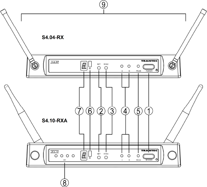
Receiver : S4.04-RX & S4.10-RXA
[Front]
1. Power switch
Press this switch to turn the power on, and press it
again to turn off the power.
2. Channel setting key [SET]
Used to select the receiving channel (frequency).
(The receiver frequency must be identical to that of
the microphone.)
3. Infrared (IR) sync key [SYNC]
Press this switch to transfer the frequency to
the transmitter.
4. Reception lamps [A, B]
Either lamp of A (left) or B (right) lights yellow
when the receiver matches a radio signal from the
transmitter.
5. AF peak lamp [PEAK]
Lights red when the receiver output level reaches
the point about 3 dB below the clipping level.
6. Infrared (IR) port [IR]
Transmit the infrared signal, when pressing
SYNC key,
7. Numerical LED display
Indicates the current channel number in normal
state.
In setting mode, the indicated channel number
flashes until registered.
8. RF signal level meter (S4.10-RXA only)
Indicates the current channel number in normal
state.
9. Antennas (S4.04-RX only)
Raise both antennas at 45° outwards from
a vertical line.
When carrying the unit, be sure to fold down
both antennas to prevent them from break.
S4.04-RX
S4.10-RXA
6
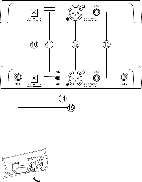
[Rear]
10. DC input jack
Connect the power cable of the supplied
AC adapter to this jack.
11. Cable hanger
Hook the power cable onto this part.
12. AF output
Balanced XLR jack, male type (Pin #2: Hot).
S4.04-RX : -20 dBu (maximum)
S4.10-RXA : 16 dBu (maximum)
13. AF output
Unbalanced phone jack
S4.04-RX and S4.10-RXA : 10 dBu (maximum)
14. Volume control (S4.10-RXA only)
Adjust the output level.
15. Antenna input A, B (S4.10-RXA only)
BNC connectors for antennas
Phantom powering for the external
antenna (optional)
For the wireless system covering a relatively
narrow area, use the supplied two rod antennas,
which should be set up at 45° outwards from
a vertical line.
Tip S4.10-RXA receiver gain is continuously adjustable. Should the receiver signal be too high, it will distort
your mixer / amplifier. If the signal is too low, the result will be an increase in general background noise.
Monitor the AF peak LED on the receiver, and adjust the volume control to achieve the best signal
quality.
S4.04-RX
S4.10-RXA
7
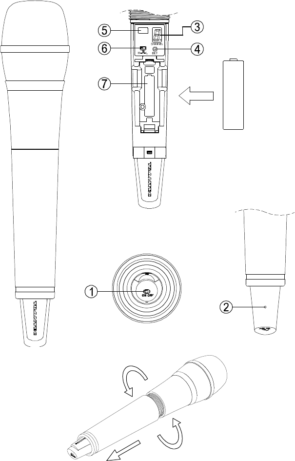
Handheld microphone : S4.04-HDX & S4.10-HDX
8
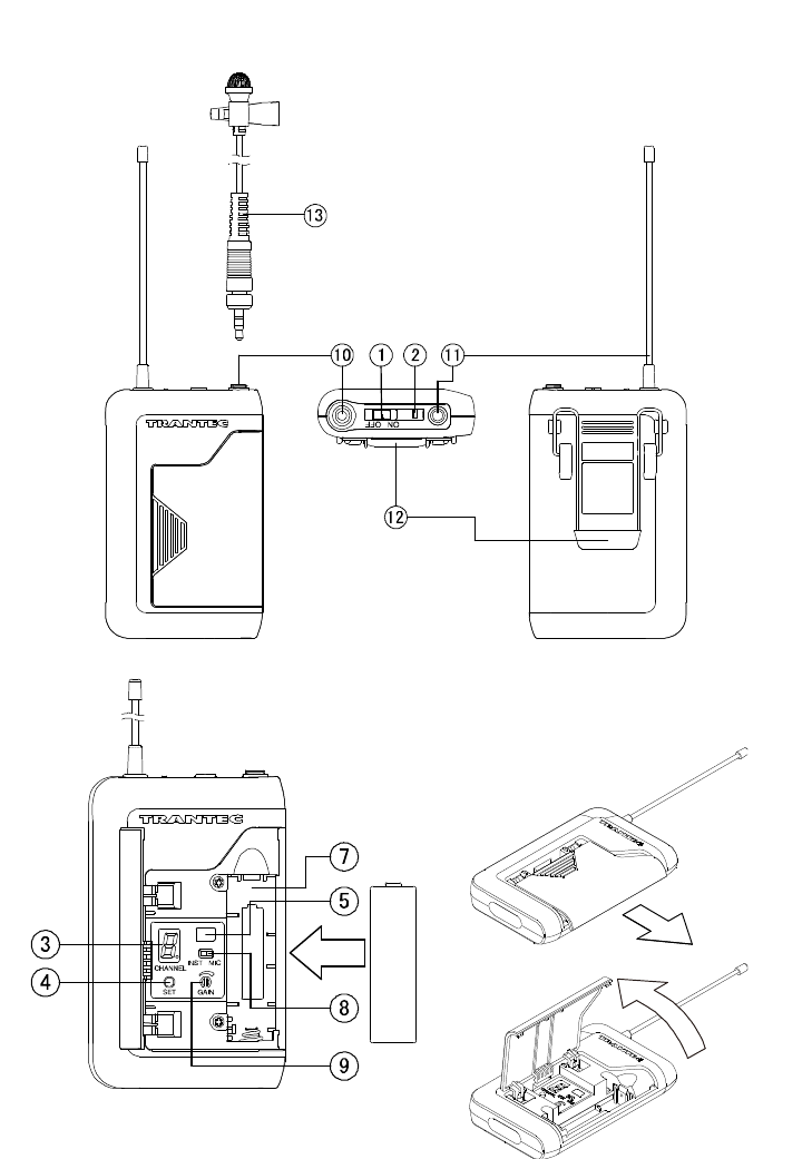
Belt-pack transmitter : S4.04-BTX & S4.10-BTX
9
1. Power switch
Slide this switch towards “ON” to turn the
power on, and slide it again towards “OFF” to
turn off the power.
2. Power / Battery lamp
A green LED lights as long as the battery
capacity is sufficient. When the battery
capacity becomes low, the green LED starts
to flash.
3. Numerical LED display
Indicates the current channel number in
normal state.
In setting mode, the indicated channel
number flashes until registered.
4. Channel setting key [SET]
Used to select the channel (frequency). (The
frequency must be identical to that of the
receiver.)
5. Infrared (IR) port
Receive the infrared signal from the receiver.
6. PAD switch (S-4.10-HDX only)
This switch is used for microphone sensitivity
adjustment .The sensitivity can be decreased
by “H” (0dB), “L” (-10dB).
Note Never position the transmitter antenna
directly against the body or hand. This
will have the effect of reducing the
operating range considerably.
7. Battery compartment
Insert an AA battery according to (+ ) and (–)
indications on the battery compartment.
Note: Turn off the power switch.
HDX:
Hold the microphone body and rotate the
microphone grip counterclockwise to remove it.
BTX
:
Slide the battery cover in the
direction indicated by the arrow while pressing
on the cover with a thumb and hinge up-wards.
8. MIC / Instrument switch (BTX only)
Slide this switch towards “MIC” to connect the
microphone, and slide it towards “INST” to
connect the instrument.
9. Audio level control (BTX only)
Adjust the audio level control using the
suppli ed screwdriver. The transmitter
sensitivity increases as the control is rotated
clockwise, and decreases as rotated
counterclockwise.
10. Input connector (BTX only)
3.5 mm j ack socket, Connect the
microphone or the instrument cable.
11. Antenna (BTX only)
12. Clip (BTX only)
Clip the transmitter to a belt through the
transmitter clip. It is better the belt should
be pressed against the base of the
transmitter clip.
13. Microphone (BTX only)
Note: Route the microphone cable so as to
avoid undue strain of friction. Try and keep the
microphone cable away from the antenna.
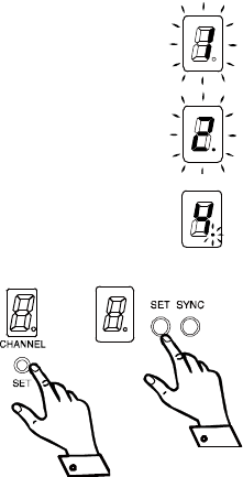
6. CHANNEL NUMBER
SETTING by MANUAL
Step 1. Press the SET key for about 3 seconds until the displayed channel number blinks.
Step 2. Select the desired channel number with the SET key, and once the desired number is
reached, release the SET key. After about 5 seconds, the receiver automatically sets
channel and the blinking number turns to steady light.
Tip Continuous or each depression of the SET key permits the display to cycle through the
channel numbers.
On the receiver side, when the dot LED by the channel number LED is blinking at
selecting channel number, this means that the channel has already been occupied.
Note Make sure that the transmitter is identical to the receiver in the channel number.
Should the microphone's setting differ from that of the receiver, the receiver does not receive the
radio signal from the transmitter.
On the transmitter side, the power switch turns on, the channel
number display turns on the light for about 30 seconds, and
then this display turns off the light. When SET key presses in
this condition, this display turns on the light for about 30
seconds.
10
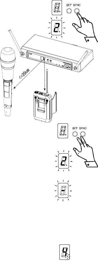
7. CHANNEL NUMBER
SETTING by
INFRARED SYNCHRONIZATION
Step 1. Confirm that the receiver is set the channel number and the transmitter is
turned the power on, and open the battery case on the transmitter.
Step 2. Bring the IR port in the transmitter within 20cm of IR port on the receiver.
Step 3. Press the SYNC key on the receiver for about 3 seconds. When the
channel data be transmitted successfully from the IR port on the receiver,
the displayed channel number flashes.
Step 4. When the channel number are synchronized
successfully between the receiver and the
transmitter, the displayed channel number in
the transmitter blinks for about 3 seconds,
Note On the transmitter side, even if the channel
number display turns off the light, the display
turns on again when IR synchronization
succeeds.
8. CHANNEL
SCAN
Step 1. Press the SET key and the SYNC key at the same time for about 3 seconds.
Channel scan begins, and an idle channel number is indicated blinking on
the channel number display.
Step 2. After channel scan finishes, the idle channels are displayed in turn.
Step 3. Press the SET key and the SYNC key at the same time, the receiver sets the
idle channel automatically.
Note Before starting the channel scan, turn off all transmitters and any other
equipment that could cause the interference during the performance so it will be detected during the
channel scan.
If there are no idle channels, the channel number is displayed blinking as a “-“.
And then the channel before starting the channel scan is set again.
Multiple System Setup
Set up each system one at a time, confirm each system is assigned a different
channel, and leave the transmitter powered on. Otherwise, the channel scan from the other receiver will
not detect as the occupied channel.
9.
BATTERY ALARM INDICATON
• When the battery capacity in the corresponding transmitter becomes low, the dot LED of the numerical LED
on the receiver and the transmitter blinks. Replace the transmitter battery.

11
10.
OPERATIONAL HINTS
• The transmitter's service distance is 3 – 100 m. When the transmitter user moves in a facility, signal
dropouts (momentary losses of signal reception) may be encountered. These dropouts are caused by the
building's architectural designs or materials which block the travel of or reflect the radio signal. If this occurs,
the user needs to change locations for better signal reception.
• Confirm the good line of sight between the transmitter and the receiver. Do not place the large obstructions
(ex. Concrete walls or large metal obstructions) between the transmitter and the receiver. In addition keep
the receiver away from the metallic beams and obstructions as these can adversely affect the antenna pick-
up pattern and induce the interference.
• The proper operation of your wireless system may be interfered with by other system operating on the same
frequency. In such cases, change the operating frequency of your system.
• Hold the microphone within 20cm from the sound source. Move the microphone closer for a warmer sound
increased. And do not cover the grille with hand.
• Keep your mouth 15 – 20 cm away from the lavalier microphone for the best possible sound reproduction. In
case of the Omni-directional response, it will pick up sounds from all directions. It is better that the
microphone is placed closer to the sound source. Take care not to bring your mouth too close to the
microphone (within 5 cm) as this impairs speech clarity if you speak loudly.
• In case of the headset microphone, by adjusting the gooseneck, locate the microphone with the supplied
windscreen in front of your mouth, and position it 3 – 5 cm away from your mouth for the best sound
reproduction. When the microphone is too close to your mouth or you speak too loud, speech clarity will be
impaired, making it hard for the audience to hear announcements.
11.
TROUBLESHOOTING
Issue Condition Solution
No sound Receiver Reception lamps
[either A or B] or RF signal level
meter lights.
Confirm the connections of all
sound system or gain
Confirm the receiver volume
control.
Sound distorted AF peak lamp [PEAK] indicates. Confirm the transmitter gain or
PAD.
Confirm the receiver volume
control.
Confirm the receiver output level
match to the input level of the
mixer / amplifier.
Poor range or sound dropouts Receiver Reception lamps [A
and B] are flicking or RF signal
level meter turn light off..
The system must be set up within
recommended range.
The transmitter must be used in
line of sight from the receiver.
Check the channel scan, confirm
nearby source of interference,
and change the receiver and the
transmitter to a different channel.
Confirm the battery indication,
and replace the transmitter
battery.

12
12.
SPECIFICATIONS
System
Modulation Wideband FM
Frequency Range UHF band (500-538, 538-576, 576-603, 603-638, 638-671,
671-701, 720-758, 785-815, 819-832, 836-867, 925-937.5 MHz)
Tunable Frequencies 25 kHz Steps
Switchable Channels S4.04 : 4 channels
S4.10 : 16 channels
Operated channels simultaneously S4.04 : 4 channels
S4.10 : up to 12 channels (depending on region)
Pilot tone 32.768kHz
Total Harmonic Distortion < 1 % @1kHz
Function IR sync, Channel scan, Battery life information
Dynamic Range >96 dB(A)
Operating Range approx. 100 m
Operating Temperature Range -10°C to +50° C
Note: 500–603 MHz and 614–698 MHz for USA/Canada, 614–698 MHz for Brazil, 865–867 MHz for India, 925-
937.5 MHz for Korea
TRANSMITTER
S4.04-HDX, S4.10-HDX S4.40-BTX, S4.10-BTX
Microphone unit Dynamic with cardioid pattern TRANTEC series lavalier and head set
microphone
RF Carrier Power 10 mW 10 mW
Audio Frequency
Response 80 - 15000 Hz 50 - 15000 Hz
Audio input Level 140 dBSPL (maximum) -6dBV (maximum), mic gain 0dB
Battery Life approx. 10 hours approx. 10 hours
Power Supply 1 AA size alkaline battery, 1.5 V 1 AA size alkaline battery, 1.5 V
Finish Resin, coating Resin, coating
Dimensions* 250 x φ55 mm 62 (W) x 100 (H) x 25 (D) mm (with clip)
Weight* 245 g (with battery) 85 g (with battery)
RECEIVER S4.04RX, S4.10-RXA
Diversity Reception Antenna Diversity
Sensitivity 10uV at 45dBA S/N
Squelch (SQ) Tone SQ, Carrier SQ, Noise SQ
Audio Frequency Response 50 - 15000 Hz
Audio Output Level
(Maximum)
S4.04-RX Balanced (XLR socket) : -20 dBu
Un-balanced (1/4" jack socket) : 10 dBu
S4.10-RXA Balanced (XLR socket) : 16 dBu
Un-balanced (1/4" jack socket) : 10 dBu
Power Supply 12 VDC 500 mA
Dimensions* 215 (W) x 39 (H) x 102 (D) mm (excluding antenna and BNC)
Weight* 480g
0dBu=0.775V
Note: The design and specifications are subject to change without notice for improvement.
• Accessory
AC adapter
Microphone holder (For handheld microphone)
Screwdriver (For setting of Belt-pack transmitter)
Color label set (10 colors)
Storage case (For transmitter)
13.
FREQUENCY TABLE