TON ELECTRONICS TECHNOLOGY TK228 OBD-II GPS Tracker User Manual

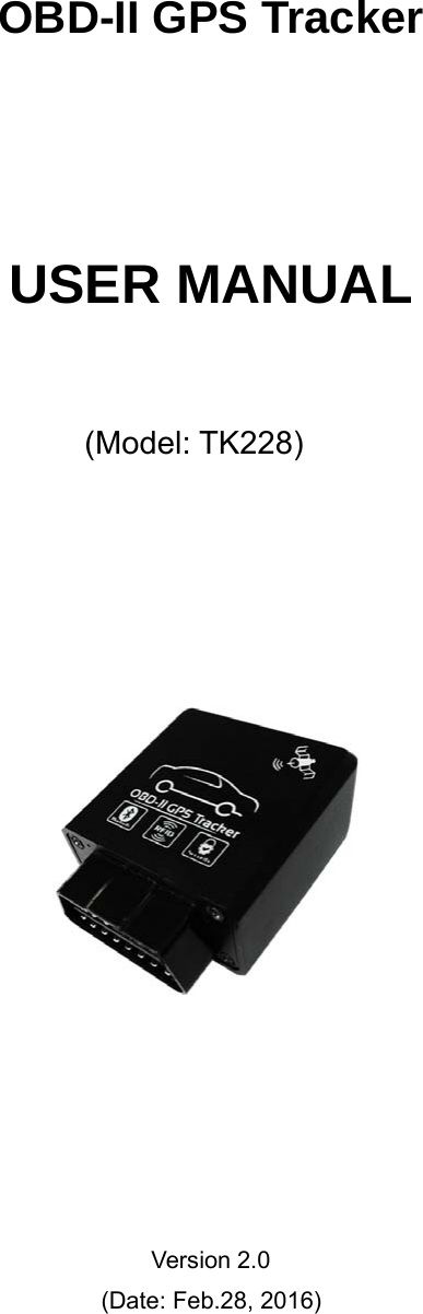
TOPTEN ELECTRONICS TECHNOLOGY LIMITED OBD-II GPS Tracker Users Manual

User Manual

OBD-II GPS TrackerUSER MANUAL(Model: TK228)Version 2.0(Date: Feb.28, 2016)
TK228 OBD-II GPS Tracker User ManualPage 1CONTENTPreface...............................................................................................................................2I. Features & Functions.....................................................................................................2II. How to operate it.......................................................................................................... 3SMS Command Format..................................................................................................................3Authorize the Alert-received Mobile..............................................................................................4Change User Password...................................................................................................................4Check the Vehicle’s Status..............................................................................................................4Arm/Disarm the System................................................................................................................. 5Check the Location by Google Map’s URL...................................................................................5Check the Real Physical Address...................................................................................................6Monitor the Voice........................................................................................................................... 6Pair the Wireless Immobilizer........................................................................................................ 7Stop/Restore the Car.......................................................................................................................7Set up the Shock Sensor................................................................................................................. 7Turn ON/OFF Sleep Mode.............................................................................................................8Check the IMEI No.........................................................................................................................8Odometer function..........................................................................................................................8Set up Movement Alert...................................................................................................................9Set up Over-speed Alert..................................................................................................................9Set up Geo-Fence Alert.................................................................................................................. 9Trace Optimization.......................................................................................................................10Reboot the Device........................................................................................................................ 10Read the Vehicle Identification No.............................................................................................. 10Set the Time for OBD Module's Entering into Sleep Mode........................................................ 10Upload Intervals of CANBUS data via GPRS.............................................................................11Change the Heart-beating Interval................................................................................................11Reset the Accumulated Fuel Reading...........................................................................................11Read & Clear the Error Code of CANBUS..................................................................................11III. Transmission of CAN-BUS Data..............................................................................12IV. The Setting for GPRS Connection.............................................................................13V. Alarm Type..................................................................................................................14VI. Installation.................................................................................................................15VII. Specifications...........................................................................................................17VIII. FAQs & Troubleshooting....................................................................................... 18
TK228 OBD-II GPS Tracker User ManualPage 2PrefaceTK228 OBD-II GPS Tracker is a multifunctional product. It is an integrationof OBD-II GPS tracker, Remote/Bluetooth Diagnostics & wireless immobilizer.It has plug & play design, which is compatible with all the cars with OBD-IIconnector, and it supports all the CAN-BUS protocols as followings:No. Protocol Name Protocol standard1 ISO9141-2 ISO91412 KWP2000_5BPS ISO142303 KWP2000_FAST4 CANBUS_11B_500KISO157655 CANBUS_29B_500K6 CANBUS_11B_250K7 CANBUS_29B_250KThe device will read vehicle's ECU's data (speed, rpm, odometer, speed,driver behavior data...etc) via CAN-BUS and send out by GPRS networkremotely or by blue-tooth connection on spot.Read it Firstly:Please read this manual thoroughly before you use the device; please keepit for future reference.Attention:(1) Please keep the device away from water, humidity, high temperature,heavy dust or strong magnetism.(2) Please prepare a valid GSM SIM card in advance.Warning:We strongly suggest user let the professional car electrician to install thesystem.I. Features &Functions1. Plug & play design with OBD-II connector, compatible with all the vehicleswith OBD-II connector, supports most of vehicles with the CAN-BUS;2. It is the integration of GPS tracker + Bluetooth diagnostics+ Wirelessimmobilizer;3. Arm/disarm by SMS/phone call;
TK228 OBD-II GPS Tracker User ManualPage 34. Check the real physical address (such as city name, street name.) directly;5. Track by SMS/website to get the latitude, longitude, speed, direction &odometer etc.;6. Movement alarm, Over-speed alarm, Geo-fence alarm;7. Engine on alarm, power failure alarm, vibration alarm;8. Anti-tamper alarm. Once the device is disconnected, it will trigger the alarm;9. Built-in shock sensor for power saving & triggering vibration alarm;10. Monitor the voice;11. Accurate odometer & speed reading directly via CAN-BUS;12. Data logger 4Mb for offline GPS waypoint;13. Wireless immobilizer to stop the car in safe mode;14. High reliable anti-tamper design. If the unit is unplug illegally, it will lock theengine automatically.15. Built-in rechargeable backup battery; when the car battery is cut off ordamaged, the built-in backup battery can work for emergency check, andthe system will send out power failure alert immediately.16. Two kinds of location information: GPS coordinates & GSM base stationcode.17. Remote diagnostics function. Transmission of the CAN data via blue-toothor GPRS network: (1) Vehicle's real-time data: battery's voltage, RPM,speed, TAP throttle opening, engine load, coolant temperature, fuelconsumption, odometer, error code & times, acceleration times &deceleration times; (2) Driver behavior data: ignition time, total driving time,total idling time, average engine hot-start time, average speed, history highspeed, history RPM, total acceleration times & total deceleration times.18. Read the vehicle's error code & clear the error code via GPRS or blue-tooth;II. How to operate itSMS Command FormatUser can send SMS instruction to operate the tracker by any mobile phone,the format of the instruction is:User Password (******) + Control Code(XXX)The default user password is 111111.
TK228 OBD-II GPS Tracker User ManualPage 4If the user password is changed, user should send the SMS instruction withthe new user password instead of 111111.XXX is the control code, all the letters must be all capital letters or smallletters, any code mixed by two of them will be not available.There is no space between the user password & the control instruction.Authorize the Alert-received MobileSMS command: 111111*10 Mobile #1*20 Mobile #2*In case of alarm, if user wants to get the alert SMS from the tracker, he/sheneeds send the following SMS to program the system firstly, otherwise, the alertinformation can not be received correctly.Example:User sends the SMS 111111*1013922713571*2013711189059* to thetracker’s SIM card number, if there is any alert, system will send alert SMS toboth of these two mobiles.Change User PasswordSMS command: 111111PSWnnnnnnThis instruction is used to change the user password. The length of theuser’s password is 3~6 digits. Users are suggested to change to the newpassword in use.Example:User sends the SMS “111111PSW12345” to the system SIM card number,and gets the confirmed SMS “111111PSW12345” in 3 seconds. It means thatthe user password has been changed to 12345.Remark: Please keep the password deep in mind if it is changed.Check the Vehicle’s StatusSMS command: 111111CHKThis instruction is used to inquiry the vehicle’s location & system’s status.The system will send back the SMS, includes the similar information, suchas “Car is Armed……”
TK228 OBD-II GPS Tracker User ManualPage 5Arm/Disarm the SystemThere are 3 ways to arm/disarm the tracker: by SMS, phone call or RFID tagBy SMS CommandSMS command: 111111ARMThis SMS instruction is used to arm the systemSMS command: 111111DSMThis SMS instruction is used to disarm the systemBy Phone CallingUser could also use the first alarm-received mobile phone to call thesystem SIM card number, so as to arm/disarm the system.Arm: After hearing several ring tones, if the systems hang up the callautomatically, and call back you, it means that the system is armed.Disarm: After hearing several ring tones, if the system hangs up the callautomatically, and don’t call back you, it means that the system is disarmed.Note:(1) There is no communication fee for this operation, it is a very convenient way to arm& disarm the system.(2)The SIM card inside the device must have the function of Caller ID Display.(3) Only the 1st authorized mobile phone can realize this function.Check the Location by Google Map’s URLCommand: 111111MAPUser can use any mobile phone to send this command to tracker’s SIMnumber, the tracker will automatically send back the SMS including the Googlemap’s URL, user can use smart phone(be able to visit internet) to open the URLlink and then the car’s location will be showed on the Google map.
TK228 OBD-II GPS Tracker User ManualPage 6Check the Real Physical AddressSMS command: 111111ADDWhen user sends this SMS command to the tracker, the tracker willautomatically send back the car’s real physical address (such as city name,street name) to your mobile by SMS.Attentions: If you want this function, you need to link your tracker into ourTS03 tracking centre.Remark:(1) The GPRS service of the tracker’s SIM card must be activated, andthe correct GPRS setting is needed (refer to the chapter of the setting ofGPRS connection), user can set up the GPRS upload time interval to 0 soas to save the GPRS flow;(2) The physical address depends on the Google map’s addressinformation. If the place has very detailed information on Google map, thenthe physical address by SMS is very detailed.Monitor the VoiceSMS command: 111111MONThis instruction is used to monitor the voice around the car.After sending out this SMS, the tracker will call back immediately, then, usercan monitor the voice around the car upon picking up the call.SMS command: 111111MON:TelThis instruction is used to program the phone number which is used for
TK228 OBD-II GPS Tracker User ManualPage 7carrying out direct monitoring or talking.User uses this phone number to call the tracker, it will be connectedautomatically without driver’s permission. By this way, user can monitor thevoice freely.Example: 111111MON:13922713571Pair the Wireless Immobilizer111111RELAYPlease power up one or more wireless immobilizers firstly & put themaround the main unit, then send the SMS command 111111RELAY to the mainunit, the immobilizers will give out Bi-Bi sounds, it means the pairing issuccessful.Stop/Restore the CarSMS command: 111111STPThis instruction is used to cut off the car’s power supply or fuel supply, so asto stop the car, user can add one or more wireless immobilizer to realize it.If the car’s speed is less than 30KM/H, the car will be stopped immediately.If the car’s speed is over 30KM/H, the instruction will not be carried out until thecar is slow down at speed of less than 30KM/H.SMS command: 111111RESIt is used to restore the car to normal status after being stopped.Set up the Shock SensorCommand:111111SHK@Normal status, when shock sensor is activated, it will trigger the alarmimmediately.@=0, turn off shake sensor.@=1, normal working mode(default setting).Normal status, when sensor is activated, it will trigger the alarm immediately.It is the default setting@=2, Time-delay working mode
TK228 OBD-II GPS Tracker User ManualPage 8Time-delay status, if the sensor is activated for 3 seconds continuously, itwill trigger the alarm. This setting can avoid some false vibration alarm.Turn ON/OFF Sleep Mode.111111SLEEP0 Turn off sleep mode, it is the default setting111111SLEEP1 Turn ON sleep mode, it is used to save power & GPRSflow. In this working mode, if the engine is OFF, the system will go into sleepmode after 3 minutes. In sleep mode, the device only reports the heart-beatingpacket by GPRS, GSM & GPS module will go into power save mode also. Oncethere is any vibration, or alarm, or incoming call/SMS, the system will wake upimmediately.Check the IMEI No.Command: 111111REGThis instruction is used to check the GSM module’s IMEI number. Last 14bits is tracker’s ID.Odometer function111111ODO:? It is used to read the present odometer value.111111ODO:R It will reset the device’s odometer reading to 00000 & startcalculation from the beginning.111111ODO:0 It will reset the device’s odometer reading to 00000 &close the calculation of odometer.111111ODO:1~999999 It will make the device to start calculation ofodometer from the base value. Example: 111111ODO:38980, then the devicewill reset the initial odometer reading as 38980KM & start the calculation again.(The commands work only when the OBD module is not in sleep mode)
TK228 OBD-II GPS Tracker User ManualPage 9Set up Movement AlertCommand: 111111MOV@@ =0, to disable the movement alert;@=1, to enable the movement alert;@=?, to check the setting of movement alert.If user sends 111111MOV1 to enable the movement alert function, themovement alert centre is your tracker’s current position. Every time whenthe system is armed, if the car moves away from the present parking pointfor about 90 meters(default setting), the movement alert will be triggered.User can change the radius of triggering movement alarm by this SMScommand: 111111MOV:R (R=50~999).Set up Over-speed Alert111111SPD:X x is the speed in KM/H , maximum value is 255M/H(For example: 111111SPD:120, if the car speed is over 120KM/H, it willsend SMS to warn you)111111SPD:0 to disable the over-speed alert. It is the default settingWhen the over-speed alert function is activated, if the car is running overthe speed limitation, the tracker will send out alert message.Set up Geo-Fence Alert111111FEN0 Disable the Geo-fence111111FEN1 Enable the Geo-fence, using the stored setting111111FEN?Check the setting of geo-fence111111FEN1(YL:a,XL:b,DL:C)Set up the all the parameters111111FEN1(YL:a)Setup the latitude separately111111FEN1(XL:b)Setup the longitude separately111111FEN1(DL:C)Setup the radius separatelyYL:a, a is latitude of the reference pointXL:b, b is the longitude of the reference point
TK228 OBD-II GPS Tracker User ManualPage 10DL:c, c is radius of latitude & longitude, the range of the value is (1-990),the unit is :100 meters. The range is 1~99000 meters.(0.1-99KM)Remark: (1) FEN, XL, YL,DL must be in capital letter.(2) The Setting will be stored and used all the time.Example: If the fence’s center coordinate is: latitude:+23.1400, longitude:+113.4500, theradius is 5KM, then the SMS instruction is:111111FEN1(YL: +23.1400,XL: +113.4500,DL:50) .If the vehicle is running across the boundary of the fence, the system will automaticallysend out alert SMS.Trace OptimizationWhen the vehicle turns around a certain angle: 30 degree, it will report onelocation, that is to optimize the trace and make the history routine looks smooth.111111DEG:1 : Enabled (default)111111DEG:0: DisabledReboot the DeviceSMS command: 111111STARTIt is to reboot the device, the settings will not changeRead the Vehicle Identification No.SMS command: 111111VINIt is to read out the vehicle's VIN no. from CANBUS.(The command works only when the OBD module is not in sleep mode)Set the Time for OBD Module's Entering into Sleep Mode.SMS command: 111111AT504=n ,(nistimeinsecond,thedefaultvalueis900seconds=15minutes. The range of n is: 0-43200 seconds).When the engine is turned OFF, the OBD module should go into sleep modefor saving power. This command is to set the waiting time to enter into sleep
TK228 OBD-II GPS Tracker User ManualPage 11mode. For example: 111111AT504=300, when the engine is turned off, the OBDmodule will go to sleep after 5 minutes(=300seconds).(The command works only when the OBD module is not in sleep mode)Upload Intervals of CANBUS data via GPRSIt is to set the time interval of upload the CANBUS data via GPRS.111111CANUP:X (X is the whole number from 0 ~1000)If the GPRS upload time interval of normal GPS coordinate packet is T, thenthe real time upload interval of CANBUS data is: T*X.For example: If user set normal GPRS upload interval as 30 seconds by this111111WWW:RPT:30; and the command 111111CANUP:5 will change theCANBUS data upload time interval as: 30*5=150 seconds.Change the Heart-beating Interval111111HRT:1~999This instruction is used to change the time interval of heart-beating GPRSdata package. The default setting is 3 minutes.If the GSM networks do not detect the tracker’s activities for a certain time, itwill close the GPRS connection and the device will be offline. User can adjustthe value so as to avoid this situation. Example: 111111HRT:5 (set time intervalof hear-beating as 5 minutes)Reset the Accumulated Fuel Reading111111fuelThis instruction is clear the accumulated fuel volume. (The command works only when the OBD module is not in sleep mode)Read & Clear the Error Code of CANBUS111111READ : It is to read the CANBUS error code, use can checkthe real problem of the car by this code
TK228 OBD-II GPS Tracker User ManualPage 12111111REMOVE : ItistocleartheCANBUSerrorcode(The commands work only when the OBD module is not in sleep mode)III. Transmission of CAN-BUS DataThe CAN-BUS data includes 3 types as followings:Real-time vehicle dataDriving behavior dataError CodeThese data can be sent to tracking platform remotely via GPRS network orsent via blue-tooth locally. The real-time vehicle data & driving behavior datacan be transmitted automatically on basis of the time interval, while the Errorcode can only be sent out after it gets the request command. If the OBD moduleis in sleep mode, it will not upload the CAN-BUS data any more.(1) Real-time vehicle data1. Battery voltage (V) 2.Engine speed (RPM) 3. Running Speed (Km/h)4. Throttle openingwidth (TPS %)5. Engine load (%) 6. Coolant temperature(℃)7. Instantaneous fuelConsumption (L/100km)8.Average fuel consumption(L/100km)9. Driving range (Km)10. Total mileage (km) 11. Single fuel consumptionvolume (L)12. Total fuel consumptionvolume (L)13. Current Error codenumbers14. Harsh acceleration No.(times)15. Harsh brake No.(times)(2) Driving behavior data1.Total ignition no. (times) 2.Total driving time (h) 3. Total idling time (h)4. Average hot start time (s) 5. Average speed (km/h) 6. History highest speed(km/h)7. History highest rotation(rpm)8. Total Harsh acceleration No.(times)9. Total Harsh brake No.(times)(3) Error code of the vehicleThe request command should be sent to the device firstly, then it will send
TK228 OBD-II GPS Tracker User ManualPage 13out the error code if it has. User can judge the malfunction type according to thecode.IV. The Setting for GPRS ConnectionThe GPRS setting is necessary for using the following 2 functions:(1) Check the car’s real physical address by send 111111ADD(2) Online tracking service by web-based tracking platform(www.track800.com )SMS format: 111111WWW:APN:APNname,APNuser,APNpassword;IPN:IP;COM:Port;RPT:time;SLP:time;GPRS:X; (separated by;)Composite SMS Command for GPRS Setting(Please kindly noted that the device GPRS ID is the last 14 digits of the IMEI,you can check it on the sticker on the device or send 111111REG to get it)User can use one SMS to do all the GPRS setting. For example, if the APNname is internet, APN user name web and APN password gprs , GPRS reporttime(Engine ON): 180seconds, (Engine OFF:):600seconds.Server’sIP:98.143.144.145, Server’s Port: 8500, then you can do all settings together inone SMS command:11111WWW:APN:internet,web,gprs;IPN:98.143.144.145;COM:8500;RPT:180;SLP:600;GPRS:1;111111WWW:IPN:XXX.XXX.XXX.XXX;COM:YYYY;This is to set the server’s IP address & port 8500E.g.: 111111WWW:IPN:98.143.144.145;COM:8500;If user wants to use domain name as server, please use DSN instead of IPNSuch as: 111111WWW:DSN:www.track800.com;If user wants to use UDP transmission, please use UDP instead of IPNSuch as: 111111WWW:UDP:98.143.144.145;COM:8500;111111WWW:APN:XXX;This is to set the APN (access point name). Please use “,” to separate the APN,APN username & APN password.E.g.: 111111WWW:APN:web.gprs.mtnnigeria.net,web,gprs;
TK228 OBD-II GPS Tracker User ManualPage 14111111WWW:RPT:XXX;This is to set the upload time interval. The unit is second, the value is between15-999 seconds.The default setting is 0, the tracker will not upload data but GPRS is online.E.g.: 111111WWW:RPT:60;(Upload time interval is every 60s)111111WWW:SLP:X ;X is the time in seconds. For example: if you want to set the report time forEngine ON is: 30seconds & Engine OFF is 3minutes(180seconds). The SMScommand is: 111111WWW:RPT:30;SLP:180;GPRS:0/1;GPRS:0; is to close down the GPRS;GPRS:1; is to open the GPRS.E.g.: 111111WWW:GPRS:1;(Open the GPRS connection)Check the GPRS Settings111111WWW:You can send 111111WWW: to check the parameters if you forgot.(with : atthe end)Default GPRS SettingThe default GPRS setting is:Server IP: www.track800.comServer Port:8500APN: internetGPRS report interval: 0GPRS connection: openV. Alarm Type.Vibration AlarmIn arming status, if the car is vibrated, the system will send out alert SMS.Power Failure Alarm
TK228 OBD-II GPS Tracker User ManualPage 15In arming status, if the device is taken off from the OBD-II connector, it willtrigger this alarm.Engine ON AlarmIn arming status, if the car engine is turned ON, it will trigger this alarm. Youwill get alert SMS firstly & then two calls from the system.Movement AlarmIn arming status, the movement alert is enabled automatically. Once the carmoves away from the parking point for 90 meters, it will trigger this alarm.Geo-Fence AlarmOnce the Geo-fence is activated, if the vehicle oversteps the boundary, itwill trigger this alarm.Over-speed AlarmIf the vehicle runs over the speed limitation, it will trigger this alarm.VI. Installation(1) Prepare the SIM CardPlease prepare a valid GSM card (CDMA card not supported) with Caller IDDisplay & GPRS function.Please make sure that main unit is powered off, and then insert SIM cardinto the SIM card holder. (Attention): If you want to take out the SIM card from
TK228 OBD-II GPS Tracker User ManualPage 16the main unit, please power off the main unit firstly, otherwise, it might damagethe unit.(2) Insert the main unit into the OBD-II connectorFor most cars, the location of the OBD-II connector is nearby the driver'splace & under the dashboard. The installation sequence is as followings:Turn ON the engine -----> Insert the device into the OBD-II connector tightly-----> Switch on the power switch of the device, make sure the LED flash ----->Wait for a while until you hear Di sound, it means that the device recognize thevehicle's CANBUS already. -----> If the RFID tag is around, you will also hear 2sounds Di -Di, it means that the RFID tag is working fine.If there is no enough space for installation, or for more secure purpose, thedevice can also be fixed at other place with extended OBD cable. Please payattention that the side with pattern should be placed upside or be kept way fromthe metal materials, because the GPS antenna is at that side.(3) Check the wiringTry to use the double-sticky paper or other material to fix the device. Fastentightly the junction point of accessories and wires. Pay attention to insulationand precaution of water and hot temperature. Please check the installationaccording to the wiring diagram.(4) Check the functionPlease check the key functions after installation, such as--Sending 111111CHK to see if it gets correct location & ACC status.---Sending 111111MON to check if monitoring is OK(5) Wiring Diagram of Wireless ImmobilizerP2P1Ground+12 WirelessImmobilizer
TK228 OBD-II GPS Tracker User ManualPage 17(Note: The relay's 2 green control output lines (P1 & P2, no polarity) can be connectedin two ways. It can be used to cut off the engine ignition loop or the fuel pump's powersupply loop. it is recommend to control the fuel pump's power supply loop)VII.SpecificationsItems SpecificationsWorking voltage: +12VDC/1.5ABackup battery: Rechargeable 3.7V 200mAh Li-ion batteryDimension (main unit): 54.0*51.5*28.5(mm)Weight (main unit): 73gGSM frequency: 2G: 850MHz1900MHz3G: 850/1900MHzGPS chipset: U-blox7 chipsetGPS sensibility -162dBmGPS receiving channel 56 channelsWorking frequencies 1575.42Mhz C/A(GPS)Positioning accuracy ≤10m (wide-open area)Speed accuracy ≤0.1M/S (wide-open area)Positioning mode Auto 2D/3DHot start 1 sec., averageWarm start 2 sec., averageCold start 40 sec., averageWorking temperature: -20 ~ 85℃Humidity: 0 ~ 95%High-Voltage Ingiton windingP1 P2Engine Ignition LoopFuel Pump's Power Supply LoopDP1 P2Fuel Pump's Motor
TK228 OBD-II GPS Tracker User ManualPage 18VIII. FAQs &TroubleshootingFAQ TroubleshootingI call the tracker, it does notring(1) The GSM SIM card has no credit;(2) The SIM card is protected by PIN code;(3) Please make sure there is no metalobstacles above the device;(4) The SIM card is placed correctly in theslot;I call the tracker, it rings, butit doesn’t send backresponse SMS(1)The user password is wrong, please usethe correct password or reset the passwordto test;(2) Low power, please use outside 12VDCpower supply to power on the unit to test(3) Check whether your command format isright or not.I can not get the alarmmessage(1) The SIM card inside the device has nocredit;(2) The Alert-received mobile number is notprogrammed correctly, or the SMS instructionis not in correct format;(3) The mailbox of the user’s mobile is full;I can not get the correct GPScoordinates or the location iswrong(1) Please make sure there is no metalobstacles above the device;(2) Please check the connection of the GPSantenna;(3) Chang another GPS antenna to test;(4) In cloudy condition, it is a little hard to getthe GPS signal, and the GPS coordinatemight have some errors.I can check the location, but Ican not get the alert SMSwhen the car moves(1) Please setup the system firstly. (authorizeSMS-received mobile number, etc);(2) In arming status,the device only warn youonce the car moves at about 50 metersaway from the parking place;The device can not recognizethe CAN BUS signal(1). The engine must be turned ON for study;(2). Power on the unit and wait for DI sound.
TK228 OBD-II GPS Tracker User ManualPage 19FCC Information and CopyrightThis equipment has been tested and found to comply with the limits for a Class B digital device,pursuant to part 15 of the FCC Rules.These limits are designed to provide reasonable protection against harmful interference in a residentialinstallation. This equipment generates,uses and can radiate radio frequency energy and, if not installed and used in accordance with theinstructions, may cause harmful interferenceto radio communications. However, there is no guarantee that interference will not occur in a particularinstallation. If this equipment doescause harmful interference to radio or television reception, which can be determined by turning theequipment off and on, the user isencouraged to try to correct the interference by one or more of the following measures:—Reorient or relocate the receiving antenna.—Increase the separation between the equipment and receiver.—Connect the equipment into an outlet on a circuit different from that to which the receiver isconnected.—Consult the dealer or an experienced radio/TV technician for help.changes or modifications not expressly approved by the party responsible for compliance couldvoid the user's authority to operate the equipment.This equipment complies with FCC radiation exposure limits set forth for an uncontrolledenvironment .This equipment should be installed and operated with minimum distance 20cmbetween the radiator& your body. This transmitter must not be co-located or operating inconjunction with any other antenna or transmitter.This device complies with part 15 of the FCC Rules. Operation is subject to the condition thatthis device does not cause harmful interference

Navigation menu