TON ELECTRONICS TECHNOLOGY TK228 OBD-II GPS Tracker User Manual
TOPTEN ELECTRONICS TECHNOLOGY LIMITED OBD-II GPS Tracker Users Manual
User Manual
OBD-II GPS Tracker
USER MANUAL
(Model: TK228)
Version 2.0
(Date: Feb.28, 2016)

TK228 OBD-II GPS Tracker User Manual
Page 1
CONTENT
Preface...............................................................................................................................2
I. Features & Functions.....................................................................................................2
II. How to operate it.......................................................................................................... 3
SMS Command Format..................................................................................................................3
Authorize the Alert-received Mobile..............................................................................................4
Change User Password...................................................................................................................4
Check the Vehicle’s Status..............................................................................................................4
Arm/Disarm the System................................................................................................................. 5
Check the Location by Google Map’s URL...................................................................................5
Check the Real Physical Address...................................................................................................6
Monitor the Voice........................................................................................................................... 6
Pair the Wireless Immobilizer........................................................................................................ 7
Stop/Restore the Car.......................................................................................................................7
Set up the Shock Sensor................................................................................................................. 7
Turn ON/OFF Sleep Mode.............................................................................................................8
Check the IMEI No.........................................................................................................................8
Odometer function..........................................................................................................................8
Set up Movement Alert...................................................................................................................9
Set up Over-speed Alert..................................................................................................................9
Set up Geo-Fence Alert.................................................................................................................. 9
Trace Optimization.......................................................................................................................10
Reboot the Device........................................................................................................................ 10
Read the Vehicle Identification No.............................................................................................. 10
Set the Time for OBD Module's Entering into Sleep Mode........................................................ 10
Upload Intervals of CANBUS data via GPRS.............................................................................11
Change the Heart-beating Interval................................................................................................11
Reset the Accumulated Fuel Reading...........................................................................................11
Read & Clear the Error Code of CANBUS..................................................................................11
III. Transmission of CAN-BUS Data..............................................................................12
IV. The Setting for GPRS Connection.............................................................................13
V. Alarm Type..................................................................................................................14
VI. Installation.................................................................................................................15
VII. Specifications...........................................................................................................17
VIII. FAQs & Troubleshooting....................................................................................... 18

TK228 OBD-II GPS Tracker User Manual
Page 2
Preface
TK228 OBD-II GPS Tracker is a multifunctional product. It is an integration
of OBD-II GPS tracker, Remote/Bluetooth Diagnostics & wireless immobilizer.
It has plug & play design, which is compatible with all the cars with OBD-II
connector, and it supports all the CAN-BUS protocols as followings:
No. Protocol Name Protocol standard
1 ISO9141-2 ISO9141
2 KWP2000_5BPS ISO14230
3 KWP2000_FAST
4 CANBUS_11B_500K
ISO15765
5 CANBUS_29B_500K
6 CANBUS_11B_250K
7 CANBUS_29B_250K
The device will read vehicle's ECU's data (speed, rpm, odometer, speed,
driver behavior data...etc) via CAN-BUS and send out by GPRS network
remotely or by blue-tooth connection on spot.
Read it Firstly:
Please read this manual thoroughly before you use the device; please keep
it for future reference.
Attention:
(1) Please keep the device away from water, humidity, high temperature,
heavy dust or strong magnetism.
(2) Please prepare a valid GSM SIM card in advance.
Warning:
We strongly suggest user let the professional car electrician to install the
system.
I. Features &Functions
1. Plug & play design with OBD-II connector, compatible with all the vehicles
with OBD-II connector, supports most of vehicles with the CAN-BUS;
2. It is the integration of GPS tracker + Bluetooth diagnostics+ Wireless
immobilizer;
3. Arm/disarm by SMS/phone call;

TK228 OBD-II GPS Tracker User Manual
Page 3
4. Check the real physical address (such as city name, street name.) directly;
5. Track by SMS/website to get the latitude, longitude, speed, direction &
odometer etc.;
6. Movement alarm, Over-speed alarm, Geo-fence alarm;
7. Engine on alarm, power failure alarm, vibration alarm;
8. Anti-tamper alarm. Once the device is disconnected, it will trigger the alarm;
9. Built-in shock sensor for power saving & triggering vibration alarm;
10. Monitor the voice;
11. Accurate odometer & speed reading directly via CAN-BUS;
12. Data logger 4Mb for offline GPS waypoint;
13. Wireless immobilizer to stop the car in safe mode;
14. High reliable anti-tamper design. If the unit is unplug illegally, it will lock the
engine automatically.
15. Built-in rechargeable backup battery; when the car battery is cut off or
damaged, the built-in backup battery can work for emergency check, and
the system will send out power failure alert immediately.
16. Two kinds of location information: GPS coordinates & GSM base station
code.
17. Remote diagnostics function. Transmission of the CAN data via blue-tooth
or GPRS network: (1) Vehicle's real-time data: battery's voltage, RPM,
speed, TAP throttle opening, engine load, coolant temperature, fuel
consumption, odometer, error code & times, acceleration times &
deceleration times; (2) Driver behavior data: ignition time, total driving time,
total idling time, average engine hot-start time, average speed, history high
speed, history RPM, total acceleration times & total deceleration times.
18. Read the vehicle's error code & clear the error code via GPRS or blue-tooth;
II. How to operate it
SMS Command Format
User can send SMS instruction to operate the tracker by any mobile phone,
the format of the instruction is:
User Password (******) + Control Code(XXX)
The default user password is 111111.

TK228 OBD-II GPS Tracker User Manual
Page 4
If the user password is changed, user should send the SMS instruction with
the new user password instead of 111111.
XXX is the control code, all the letters must be all capital letters or small
letters, any code mixed by two of them will be not available.
There is no space between the user password & the control instruction.
Authorize the Alert-received Mobile
SMS command: 111111*10 Mobile #1*20 Mobile #2*
In case of alarm, if user wants to get the alert SMS from the tracker, he/she
needs send the following SMS to program the system firstly, otherwise, the alert
information can not be received correctly.
Example:
User sends the SMS 111111*1013922713571*2013711189059* to the
tracker’s SIM card number, if there is any alert, system will send alert SMS to
both of these two mobiles.
Change User Password
SMS command: 111111PSWnnnnnn
This instruction is used to change the user password. The length of the
user’s password is 3~6 digits. Users are suggested to change to the new
password in use.
Example:
User sends the SMS “111111PSW12345” to the system SIM card number,
and gets the confirmed SMS “111111PSW12345” in 3 seconds. It means that
the user password has been changed to 12345.
Remark: Please keep the password deep in mind if it is changed.
Check the Vehicle’s Status
SMS command: 111111CHK
This instruction is used to inquiry the vehicle’s location & system’s status.
The system will send back the SMS, includes the similar information, such
as “Car is Armed……”

TK228 OBD-II GPS Tracker User Manual
Page 5
Arm/Disarm the System
There are 3 ways to arm/disarm the tracker: by SMS, phone call or RFID tag
By SMS Command
SMS command: 111111ARM
This SMS instruction is used to arm the system
SMS command: 111111DSM
This SMS instruction is used to disarm the system
By Phone Calling
User could also use the first alarm-received mobile phone to call the
system SIM card number, so as to arm/disarm the system.
Arm: After hearing several ring tones, if the systems hang up the call
automatically, and call back you, it means that the system is armed.
Disarm: After hearing several ring tones, if the system hangs up the call
automatically, and don’t call back you, it means that the system is disarmed.
Note:
(1) There is no communication fee for this operation, it is a very convenient way to arm
& disarm the system.
(2)The SIM card inside the device must have the function of Caller ID Display.
(3) Only the 1st authorized mobile phone can realize this function.
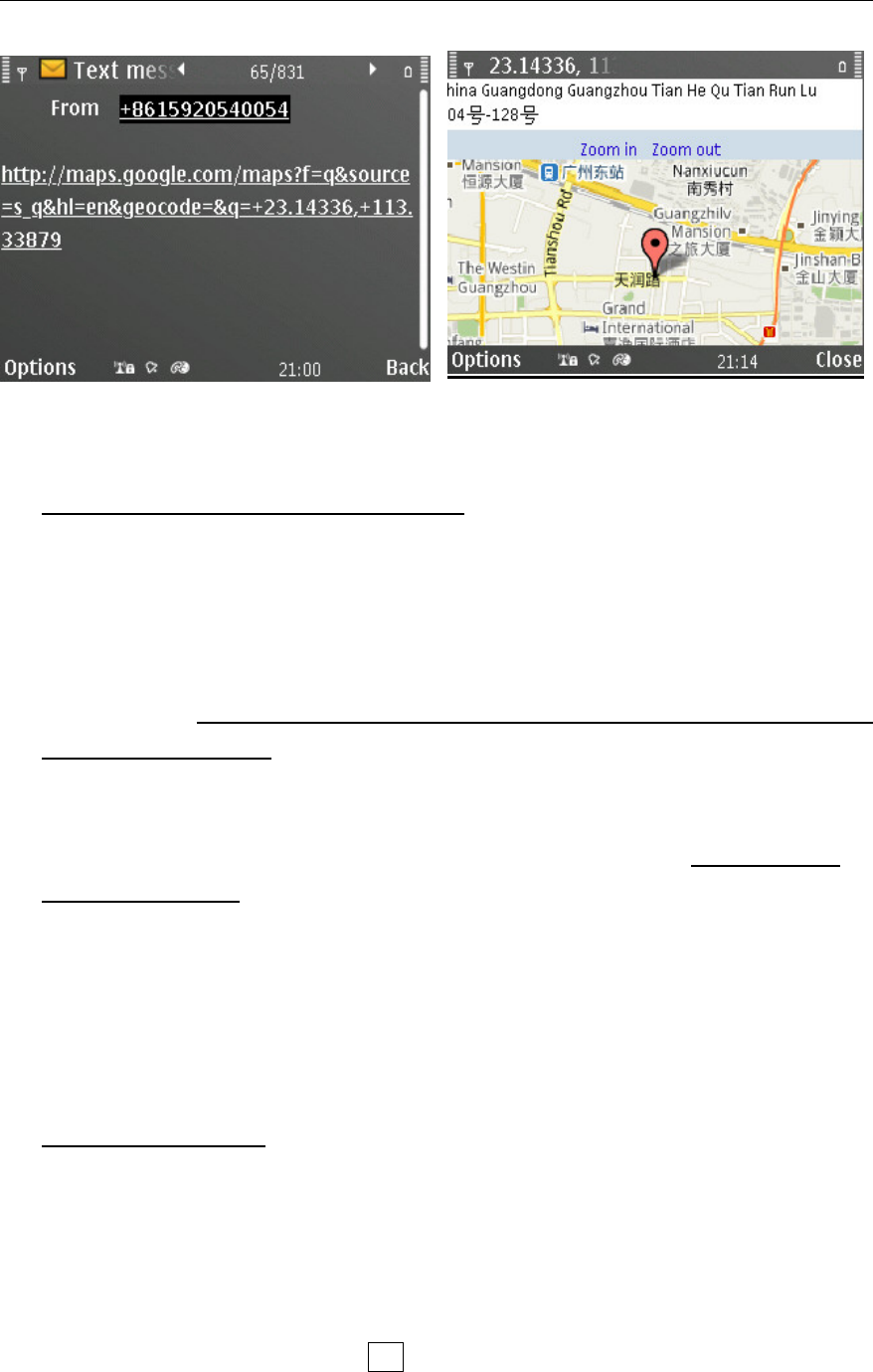
Check the Location by Google Map’s URL
Command: 111111MAP
User can use any mobile phone to send this command to tracker’s SIM
number, the tracker will automatically send back the SMS including the Google
map’s URL, user can use smart phone(be able to visit internet) to open the URL
link and then the car’s location will be showed on the Google map.
TK228 OBD-II GPS Tracker User Manual
Page 6
Check the Real Physical Address
SMS command: 111111ADD
When user sends this SMS command to the tracker, the tracker will
automatically send back the car’s real physical address (such as city name,
street name) to your mobile by SMS.
Attentions: If you want this function, you need to link your tracker into our
TS03 tracking centre.
Remark:
(1) The GPRS service of the tracker’s SIM card must be activated, and
the correct GPRS setting is needed (refer to the chapter of the setting of
GPRS connection), user can set up the GPRS upload time interval to 0 so
as to save the GPRS flow;
(2) The physical address depends on the Google map’s address
information. If the place has very detailed information on Google map, then
the physical address by SMS is very detailed.
Monitor the Voice
SMS command: 111111MON
This instruction is used to monitor the voice around the car.
After sending out this SMS, the tracker will call back immediately, then, user
can monitor the voice around the car upon picking up the call.
SMS command: 111111MON:Tel
This instruction is used to program the phone number which is used for

TK228 OBD-II GPS Tracker User Manual
Page 7
carrying out direct monitoring or talking.
User uses this phone number to call the tracker, it will be connected
automatically without driver’s permission. By this way, user can monitor the
voice freely.
Example: 111111MON:13922713571
Pair the Wireless Immobilizer
111111RELAY
Please power up one or more wireless immobilizers firstly & put them
around the main unit, then send the SMS command 111111RELAY to the main
unit, the immobilizers will give out Bi-Bi sounds, it means the pairing is
successful.
Stop/Restore the Car
SMS command: 111111STP
This instruction is used to cut off the car’s power supply or fuel supply, so as
to stop the car, user can add one or more wireless immobilizer to realize it.
If the car’s speed is less than 30KM/H, the car will be stopped immediately.
If the car’s speed is over 30KM/H, the instruction will not be carried out until the
car is slow down at speed of less than 30KM/H.
SMS command: 111111RES
It is used to restore the car to normal status after being stopped.
Set up the Shock Sensor
Command:111111SHK@
Normal status, when shock sensor is activated, it will trigger the alarm
immediately.
@=0, turn off shake sensor.
@=1, normal working mode(default setting).
Normal status, when sensor is activated, it will trigger the alarm immediately.
It is the default setting
@=2, Time-delay working mode

TK228 OBD-II GPS Tracker User Manual
Page 8
Time-delay status, if the sensor is activated for 3 seconds continuously, it
will trigger the alarm. This setting can avoid some false vibration alarm.
Turn ON/OFF Sleep Mode.
111111SLEEP0 Turn off sleep mode, it is the default setting
111111SLEEP1 Turn ON sleep mode, it is used to save power & GPRS
flow. In this working mode, if the engine is OFF, the system will go into sleep
mode after 3 minutes. In sleep mode, the device only reports the heart-beating
packet by GPRS, GSM & GPS module will go into power save mode also. Once
there is any vibration, or alarm, or incoming call/SMS, the system will wake up
immediately.
Check the IMEI No.
Command: 111111REG
This instruction is used to check the GSM module’s IMEI number. Last 14
bits is tracker’s ID.
Odometer function
111111ODO:? It is used to read the present odometer value.
111111ODO:R It will reset the device’s odometer reading to 00000 & start
calculation from the beginning.
111111ODO:0 It will reset the device’s odometer reading to 00000 &
close the calculation of odometer.
111111ODO:1~999999 It will make the device to start calculation of
odometer from the base value. Example: 111111ODO:38980, then the device
will reset the initial odometer reading as 38980KM & start the calculation again.
(The commands work only when the OBD module is not in sleep mode)

TK228 OBD-II GPS Tracker User Manual
Page 9
Set up Movement Alert
Command: 111111MOV@
@ =0, to disable the movement alert;
@=1, to enable the movement alert;
@=?, to check the setting of movement alert.
If user sends 111111MOV1 to enable the movement alert function, the
movement alert centre is your tracker’s current position. Every time when
the system is armed, if the car moves away from the present parking point
for about 90 meters(default setting), the movement alert will be triggered.
User can change the radius of triggering movement alarm by this SMS
command: 111111MOV:R (R=50~999).
Set up Over-speed Alert
111111SPD:X x is the speed in KM/H , maximum value is 255M/H
(For example: 111111SPD:120, if the car speed is over 120KM/H, it will
send SMS to warn you)
111111SPD:0 to disable the over-speed alert. It is the default setting
When the over-speed alert function is activated, if the car is running over
the speed limitation, the tracker will send out alert message.
Set up Geo-Fence Alert
111111FEN0 Disable the Geo-fence
111111FEN1 Enable the Geo-fence, using the stored setting
111111FEN?Check the setting of geo-fence
111111FEN1(YL:a,XL:b,DL:C)Set up the all the parameters
111111FEN1(YL:a)Setup the latitude separately
111111FEN1(XL:b)Setup the longitude separately
111111FEN1(DL:C)Setup the radius separately
YL:a, a is latitude of the reference point
XL:b, b is the longitude of the reference point

TK228 OBD-II GPS Tracker User Manual
Page 10
DL:c, c is radius of latitude & longitude, the range of the value is (1-990),
the unit is :100 meters. The range is 1~99000 meters.(0.1-99KM)
Remark: (1) FEN, XL, YL,DL must be in capital letter.
(2) The Setting will be stored and used all the time.
Example: If the fence’s center coordinate is: latitude:+23.1400, longitude:+113.4500, the
radius is 5KM, then the SMS instruction is:
111111FEN1(YL: +23.1400,XL: +113.4500,DL:50) .
If the vehicle is running across the boundary of the fence, the system will automatically
send out alert SMS.
Trace Optimization
When the vehicle turns around a certain angle: 30 degree, it will report one
location, that is to optimize the trace and make the history routine looks smooth.
111111DEG:1 : Enabled (default)
111111DEG:0: Disabled
Reboot the Device
SMS command: 111111START
It is to reboot the device, the settings will not change
Read the Vehicle Identification No.
SMS command: 111111VIN
It is to read out the vehicle's VIN no. from CANBUS.
(The command works only when the OBD module is not in sleep mode)
Set the Time for OBD Module's Entering into Sleep Mode.
SMS command: 111111AT504=n ,(nistimeinsecond,thedefaultvalueis
900seconds=15minutes. The range of n is: 0-43200 seconds).
When the engine is turned OFF, the OBD module should go into sleep mode
for saving power. This command is to set the waiting time to enter into sleep

TK228 OBD-II GPS Tracker User Manual
Page 11
mode. For example: 111111AT504=300, when the engine is turned off, the OBD
module will go to sleep after 5 minutes(=300seconds).
(The command works only when the OBD module is not in sleep mode)
Upload Intervals of CANBUS data via GPRS
It is to set the time interval of upload the CANBUS data via GPRS.
111111CANUP:X (X is the whole number from 0 ~1000)
If the GPRS upload time interval of normal GPS coordinate packet is T, then
the real time upload interval of CANBUS data is: T*X.
For example: If user set normal GPRS upload interval as 30 seconds by this
111111WWW:RPT:30; and the command 111111CANUP:5 will change the
CANBUS data upload time interval as: 30*5=150 seconds.
Change the Heart-beating Interval
111111HRT:1~999
This instruction is used to change the time interval of heart-beating GPRS
data package. The default setting is 3 minutes.
If the GSM networks do not detect the tracker’s activities for a certain time, it
will close the GPRS connection and the device will be offline. User can adjust
the value so as to avoid this situation. Example: 111111HRT:5 (set time interval
of hear-beating as 5 minutes)
Reset the Accumulated Fuel Reading
111111fuel
This instruction is clear the accumulated fuel volume
. (The command works only when the OBD module is not in sleep mode)
Read & Clear the Error Code of CANBUS
111111READ : It is to read the CANBUS error code, use can check
the real problem of the car by this code

TK228 OBD-II GPS Tracker User Manual
Page 12
111111REMOVE : ItistocleartheCANBUSerrorcode
(The commands work only when the OBD module is not in sleep mode)
III. Transmission of CAN-BUS Data
The CAN-BUS data includes 3 types as followings:
Real-time vehicle data
Driving behavior data
Error Code
These data can be sent to tracking platform remotely via GPRS network or
sent via blue-tooth locally. The real-time vehicle data & driving behavior data
can be transmitted automatically on basis of the time interval, while the Error
code can only be sent out after it gets the request command. If the OBD module
is in sleep mode, it will not upload the CAN-BUS data any more.
(1) Real-time vehicle data
1. Battery voltage (V) 2.Engine speed (RPM) 3. Running Speed (Km/h)
4. Throttle opening
width (TPS %)
5. Engine load (%) 6. Coolant temperature
(℃)
7. Instantaneous fuel
Consumption (L/100km)
8.Average fuel consumption
(L/100km)
9. Driving range (Km)
10. Total mileage (km) 11. Single fuel consumption
volume (L)
12. Total fuel consumption
volume (L)
13. Current Error code
numbers
14. Harsh acceleration No.
(times)
15. Harsh brake No.
(times)
(2) Driving behavior data
1.Total ignition no. (times) 2.Total driving time (h) 3. Total idling time (h)
4. Average hot start time (s) 5. Average speed (km/h) 6. History highest speed
(km/h)
7. History highest rotation
(rpm)
8. Total Harsh acceleration No.
(times)
9. Total Harsh brake No.
(times)
(3) Error code of the vehicle
The request command should be sent to the device firstly, then it will send

TK228 OBD-II GPS Tracker User Manual
Page 13
out the error code if it has. User can judge the malfunction type according to the
code.
IV. The Setting for GPRS Connection
The GPRS setting is necessary for using the following 2 functions:
(1) Check the car’s real physical address by send 111111ADD
(2) Online tracking service by web-based tracking platform
(www.track800.com )
SMS format: 111111WWW:APN:APNname,APNuser,APNpassword;
IPN:IP;COM:Port;RPT:time;SLP:time;GPRS:X; (separated by;)
Composite SMS Command for GPRS Setting
(Please kindly noted that the device GPRS ID is the last 14 digits of the IMEI,
you can check it on the sticker on the device or send 111111REG to get it)
User can use one SMS to do all the GPRS setting. For example, if the APN
name is internet, APN user name web and APN password gprs , GPRS report
time(Engine ON): 180seconds, (Engine OFF:):600seconds.Server’sIP:
98.143.144.145, Server’s Port: 8500, then you can do all settings together in
one SMS command:
11111WWW:APN:internet,web,gprs;IPN:98.143.144.145;COM:8500;RPT:180;SLP:600;
GPRS:1;
111111WWW:IPN:XXX.XXX.XXX.XXX;COM:YYYY;
This is to set the server’s IP address & port 8500
E.g.: 111111WWW:IPN:98.143.144.145;COM:8500;
If user wants to use domain name as server, please use DSN instead of IPN
Such as: 111111WWW:DSN:www.track800.com;
If user wants to use UDP transmission, please use UDP instead of IPN
Such as: 111111WWW:UDP:98.143.144.145;COM:8500;
111111WWW:APN:XXX;
This is to set the APN (access point name). Please use “,” to separate the APN,
APN username & APN password.
E.g.: 111111WWW:APN:web.gprs.mtnnigeria.net,web,gprs;

TK228 OBD-II GPS Tracker User Manual
Page 14
111111WWW:RPT:XXX;
This is to set the upload time interval. The unit is second, the value is between
15-999 seconds.
The default setting is 0, the tracker will not upload data but GPRS is online.
E.g.: 111111WWW:RPT:60;(Upload time interval is every 60s)
111111WWW:SLP:X ;
X is the time in seconds. For example: if you want to set the report time for
Engine ON is: 30seconds & Engine OFF is 3minutes(180seconds). The SMS
command is: 111111WWW:RPT:30;SLP:180;
GPRS:0/1;
GPRS:0; is to close down the GPRS;
GPRS:1; is to open the GPRS.
E.g.: 111111WWW:GPRS:1;(Open the GPRS connection)
Check the GPRS Settings
111111WWW:
You can send 111111WWW: to check the parameters if you forgot.(with : at
the end)
Default GPRS Setting
The default GPRS setting is:
Server IP: www.track800.com
Server Port:8500
APN: internet
GPRS report interval: 0
GPRS connection: open
V. Alarm Type
.Vibration Alarm
In arming status, if the car is vibrated, the system will send out alert SMS.
Power Failure Alarm
TK228 OBD-II GPS Tracker User Manual
Page 15
In arming status, if the device is taken off from the OBD-II connector, it will
trigger this alarm.
Engine ON Alarm
In arming status, if the car engine is turned ON, it will trigger this alarm. You
will get alert SMS firstly & then two calls from the system.
Movement Alarm
In arming status, the movement alert is enabled automatically. Once the car
moves away from the parking point for 90 meters, it will trigger this alarm.
Geo-Fence Alarm
Once the Geo-fence is activated, if the vehicle oversteps the boundary, it
will trigger this alarm.
Over-speed Alarm
If the vehicle runs over the speed limitation, it will trigger this alarm.
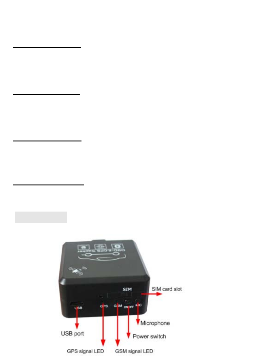
VI. Installation
(1) Prepare the SIM Card
Please prepare a valid GSM card (CDMA card not supported) with Caller ID
Display & GPRS function.
Please make sure that main unit is powered off, and then insert SIM card
into the SIM card holder. (Attention): If you want to take out the SIM card from

TK228 OBD-II GPS Tracker User Manual
Page 16
the main unit, please power off the main unit firstly, otherwise, it might damage
the unit.
(2) Insert the main unit into the OBD-II connector
For most cars, the location of the OBD-II connector is nearby the driver's
place & under the dashboard. The installation sequence is as followings:
Turn ON the engine -----> Insert the device into the OBD-II connector tightly
-----> Switch on the power switch of the device, make sure the LED flash ----->
Wait for a while until you hear Di sound, it means that the device recognize the
vehicle's CANBUS already. -----> If the RFID tag is around, you will also hear 2
sounds Di -Di, it means that the RFID tag is working fine.
If there is no enough space for installation, or for more secure purpose, the
device can also be fixed at other place with extended OBD cable. Please pay
attention that the side with pattern should be placed upside or be kept way from
the metal materials, because the GPS antenna is at that side.
(3) Check the wiring
Try to use the double-sticky paper or other material to fix the device. Fasten
tightly the junction point of accessories and wires. Pay attention to insulation
and precaution of water and hot temperature. Please check the installation
according to the wiring diagram.
(4) Check the function
Please check the key functions after installation, such as
--Sending 111111CHK to see if it gets correct location & ACC status.
---Sending 111111MON to check if monitoring is OK
(5) Wiring Diagram of Wireless Immobilizer
P2
P1
Ground
+12 Wireless
Immobilizer

TK228 OBD-II GPS Tracker User Manual
Page 17
(Note: The relay's 2 green control output lines (P1 & P2, no polarity) can be connected
in two ways. It can be used to cut off the engine ignition loop or the fuel pump's power
supply loop. it is recommend to control the fuel pump's power supply loop)
VII.Specifications
Items Specifications
Working voltage: +12VDC/1.5A
Backup battery: Rechargeable 3.7V 200mAh Li-ion battery
Dimension (main unit): 54.0*51.5*28.5(mm)
Weight (main unit): 73g
GSM frequency: 2G: 850MHz1900MHz
3G: 850/1900MHz
GPS chipset: U-blox7 chipset
GPS sensibility -162dBm
GPS receiving channel 56 channels
Working frequencies 1575.42Mhz C/A(GPS)
Positioning accuracy ≤10m (wide-open area)
Speed accuracy ≤0.1M/S (wide-open area)
Positioning mode Auto 2D/3D
Hot start 1 sec., average
Warm start 2 sec., average
Cold start 40 sec., average
Working temperature: -20 ~ 85℃
Humidity: 0 ~ 95%
High-Voltage Ingiton winding
P1 P2
Engine Ignition Loop
Fuel Pump's Power Supply Loop
D
P1 P2
Fuel Pump's Motor

TK228 OBD-II GPS Tracker User Manual
Page 18
VIII. FAQs &Troubleshooting
FAQ Troubleshooting
I call the tracker, it does not
ring
(1) The GSM SIM card has no credit;
(2) The SIM card is protected by PIN code;
(3) Please make sure there is no metal
obstacles above the device;
(4) The SIM card is placed correctly in the
slot;
I call the tracker, it rings, but
it doesn’t send back
response SMS
(1)The user password is wrong, please use
the correct password or reset the password
to test;
(2) Low power, please use outside 12VDC
power supply to power on the unit to test
(3) Check whether your command format is
right or not.
I can not get the alarm
message
(1) The SIM card inside the device has no
credit;
(2) The Alert-received mobile number is not
programmed correctly, or the SMS instruction
is not in correct format;
(3) The mailbox of the user’s mobile is full;
I can not get the correct GPS
coordinates or the location is
wrong
(1) Please make sure there is no metal
obstacles above the device;
(2) Please check the connection of the GPS
antenna;
(3) Chang another GPS antenna to test;
(4) In cloudy condition, it is a little hard to get
the GPS signal, and the GPS coordinate
might have some errors.
I can check the location, but I
can not get the alert SMS
when the car moves
(1) Please setup the system firstly. (authorize
SMS-received mobile number, etc);
(2) In arming status,the device only warn you
once the car moves at about 50 meters
away from the parking place;
The device can not recognize
the CAN BUS signal
(1). The engine must be turned ON for study;
(2). Power on the unit and wait for DI sound.

TK228 OBD-II GPS Tracker User Manual
Page 19
FCC Information and Copyright
This equipment has been tested and found to comply with the limits for a Class B digital device,
pursuant to part 15 of the FCC Rules.
These limits are designed to provide reasonable protection against harmful interference in a residential
installation. This equipment generates,
uses and can radiate radio frequency energy and, if not installed and used in accordance with the
instructions, may cause harmful interference
to radio communications. However, there is no guarantee that interference will not occur in a particular
installation. If this equipment does
cause harmful interference to radio or television reception, which can be determined by turning the
equipment off and on, the user is
encouraged to try to correct the interference by one or more of the following measures:
—Reorient or relocate the receiving antenna.
—Increase the separation between the equipment and receiver.
—Connect the equipment into an outlet on a circuit different from that to which the receiver is
connected.
—Consult the dealer or an experienced radio/TV technician for help.
changes or modifications not expressly approved by the party responsible for compliance could
void the user's authority to operate the equipment.
This equipment complies with FCC radiation exposure limits set forth for an uncontrolled
environment .This equipment should be installed and operated with minimum distance 20cm
between the radiator& your body. This transmitter must not be co-located or operating in
conjunction with any other antenna or transmitter.
This device complies with part 15 of the FCC Rules. Operation is subject to the condition that
this device does not cause harmful interference