TON ELECTRONICS TECHNOLOGY TK310 GPS Vehicle Tracker User Manual
TOPTEN ELECTRONICS TECHNOLOGY LIMITED GPS Vehicle Tracker
User Manual

TOPTEN GPS
Updated on 6/1/2010
GPS
Vehicle
Tracker
USER MANUAL
V5.0
TK310

TOPTEN GPS
- 2 -
Contents
1 Product Overview 3
2 For Your Safety 3
3 TK310 Parameters 3
4 Getting Started 4
4.1 Hardware and Accessories 4
4.2 Light and Button Functionality 4
4.3 Connecting and Installation 5
4.4 Examples of Interfacing Application 6
5 SMS Command 9
5.1 Basic SMS Commands 9
5.1.1 Position Report 9
5.1.2 Set Interval for Automatic Timed Report 9
5.1.3 Stop Automatic Timed Report 10
5.2 GPRS Setting by SMS 10
5.2.1 Set ID for TK310 10
5.2.2 Set APN 10
5.2.3 Set IP Address and Port 10
5.2.4 Set Time Interval for Sending GPRS Packet 10
5.2.5 Enable GPRS Tracking Function 10
6 Tracking on Map 11
7 Troubleshooting 12
8 SMS Command List 13
TOPTEN GPS
- 3 -
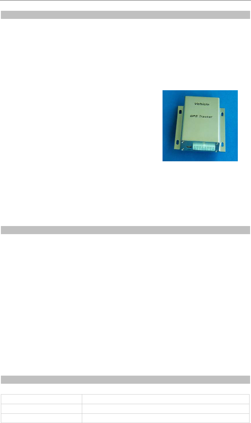
1 Product Overview
TK310 is a GPS/GSM/GPRS tracking device which is specially developed and designed for vehicle
real-time tracking and security. With superior GPS and GPRS modules, TK310 has good sensitivity and
stable performance. It can get accurate GPS fix even in remote places.
Main Features:
Tracking via SMS or GPRS (TCP/UDP)
Current location report
Tracking by time interval
Position logging capacity up to 260,000+ waypoints
Built-in motion sensor for power saving
SOS panic button
Geo-fencing control
Low battery alert
Speeding alert
Engine Cut
Wiretapping (optional)
Alert when TK310 enters/exits GPS blind area
Alert when TK310 is turned on
I/O: 5 digital inputs, 3 negative and 2 positive triggering; 5 outputs.
Analog Input: 2 10 bits resolution analog inputs
2 For Your Safety
Read these simple guidelines. Not following them may be dangerous or illegal. Read the full user manual
for more information.
Proper Connection - When connecting with other device, read carefully its manual so as to carry out
correct installation. Do not connect it to other incompatible devices.
Qualified Accessories - Use original parts, qualified batteries and peripheral equipments to avoid damage
to TK310.
Safe Driving - Drivers should not operate this product while driving.
Qualified Service - Only qualified personnel can install or repair TK310.
Water Resistance - TK310 is not water resistant. Keep it dry. Install it inside the vehicle or use waterproof
bag if necessary.
Confidential Phone Number - For safety reason, do not tell other people the mobile phone number of your
TK310 without taking precautions of security settings.
3 TK310 Parameters
Power Supply +9V - +35V / 1.5A
Backup Battery 750mAh
Dimension 104mm x 62mm x 24mm

TOPTEN GPS
- 4 -
Installation Dimension 104mm x 83mm x 24mm
Weight 150g
Operating temperature -20° to 55° C
Humidity 5% to 95% Non-condensing
Frequency GSM 850/900/1800/1900Mhz
GPS Module latest GPS SIRF-Star III chipset
GPS Sensitivity -158Db
GPS Frequency L1, 1575.42 MHz
GSM antenna’s Gain 3.5dBi
GPS antenna’s Gain Antenna Gain: -3dBic at 10°; 3.5dBic at zenith;
Amplified Gain: 27dB typ.
C/A Code 1.023 MHz chip rate
Channels 20 channel all-in-view tracking
Position Accuracy 10 meters, 2D RMS
Velocity Accuracy 0.1 m/s
Time Accuracy 1 us synchronized to GPS time
Default datum WGS-84
Reacquisition 0.1 sec., average
Hot start 1 sec., average
Warm start 38 sec., average
Cold start 42 sec., average
Altitude Limit 18,000 meters (60,000 feet) max.
Velocity Limit 515 meters/second (1000 knots) max.
LED 2 LED lights to show GPS/GSM working status.
Flash Memory 8MB
Interface 5 digital inputs, 3 negative and 2 positive triggering; 2 analog inputs;
5 outputs.
4 Getting Started
This section will describe how to set up your TK310.
4.1 Hardware Features
The standard package of TK310 includes:
• TK310 Main Unit
• GPS Antenna
• GSM Antenna
• Wires
• USB Cable
• Relay
• CD including
- User Manual
- Other document or software if required
4.2 Light and Button Functionality

TOPTEN GPS
- 5 -
Blue LED - indicating GPS status
On One or more inputs are active
Flashing ( every 0.1 second) The unit is being Initialized
Flashing (on for 0.1 second and off for 2.9 seconds) TK310 has a GPS fix
Flashing (on for 1 second and off for 2 seconds) TK310 has no GPS fix
Green LED - indicating GSM status
On One call is coming in/ one call is being made
Flashing ( every 0.1 second) The unit is being Initialized
Flashing (on for 0.1 second and off for 2.9 seconds) TK310 is connected to the GSM network
Flashing (on for 1 second and off for 2 seconds) TK310 is not connected to the GSM network
SOS Button Press it to send SMS alert
4.3 Connecting and Installation
Read this manual before using your TK310 and check if all parts are included in the packaging box.
Ensure that your TK310 has a working SIM installed.
- Check that the SIM has not run out of credit (test the SIM in a phone to make sure it can send and
receive SMS)
- Check that the SIM Lock code is turned off
- If you require the function of sending an SMS location report to the authorized phone number when it
makes a call to the TK310, please make sure the SIM installed supports displaying caller ID.
Before inserting SIM card, turn off the power for the tracker’s main unit.
Install SIM Card
- Press the yellow button beside the SIM card slot to spring out the SIM card holder.
- Insert the SIM card to the holder, then insert it into the card slot, please make sure to insert it with the
chip module facing to the connectors on PCB.
Connect the GSM Antenna to the unit.
Connect the GPS Antenna to the unit.
- GPS antenna is used to receive satellite signals upside the sky. It should be fixed to face the sky and
should not be covered or shielded by any objects containing metal, such as the metallic windshield.
Find a suitable place inside the car for installing the unit. Wiring connections must be firm and reliable
and the joints should be wrapped with insulating tape tightly. The unused electrical wire should be
properly insulated.
Check if all wirings have been connected correctly and then connect the unit to the vehicle power.
A connector for microphone is set in the PCB. If you need to link with an extra microphone for wiretapping
purpose, contact us to add this optional function before we deliver the devices to you.
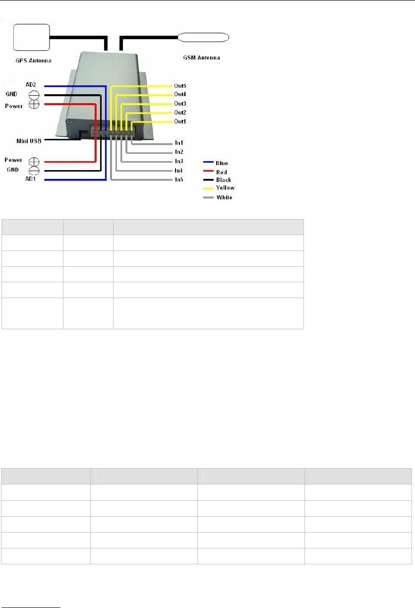
Installation Guide:
TOPTEN GPS
- 6 -
Descriptions of PINs
Pin Color Function
1 Red DC In. Input voltage: 9V~35V. 12V suggested.
2 Black GND
3 White Digital Inputs
4 Yellow Outputs
5 Blue 10 Bits Resolution Analog Inputs.
Input voltage: 0~6V.
Mini USB Port
Connect the tracker with computer by USB cable for configuration and reading stored waypoints data.
You need to install the driver - CP210x Driver Installer - for using the USB cable.
Refer to <GPS Tracker Parameter Editor> for configuration and <GPSLog User Guide> for reading
stored waypoints.
4.4 Examples of Interfacing Application
Level of the PINS
Pin Normally (inactive) Level of active Limit of input
Input 1/2/3 3V 0V 45V
Input 4/5 0V 3-40V 45V
Output 1/2/3/4/5 About 0V 0V 45V/500mA
DC IN / 9-36V 45V
AD 1/2 0V 0-6V Not higher than DC IN
Examples of Interfacing Application
For Input Ports
1. Input1 also named SOS Button (Key1) and Input2 named B Button (Key2), Input3 named C Button
(Key3). They are negative triggering. You can set an authorized phone number for it to receiving
SMS alarm or calling when it is pressed to negative(0V). Please Refer to <GPS Tracker
Parameter Editor> or <SMS Command List> for configuration phone number.
TOPTEN GPS
- 7 -
2. Detecting Lock Status of Car’s Door or Trunk(Car Boot).
When the lock is opened, there will be negative triggering to Input 1 or Input 2 or Input 3, then a SMS
alarm is sent to the authorized phone number and a GPRS alarm is sent to the Server (please refer to the
GPRS Command 0x9999).
3. Connecting with Sensors (such as sensor for detecting someone is seated). The SMS alarm will be
sent to the authorize phone number of the button.
4. Ignition Detection - Input 4 / Input 5, they are positive triggering, The detection will be send to Server
as a alarm via GPRS. Please refer to GPRS Communication Protocol Alarm Command 0x9999.
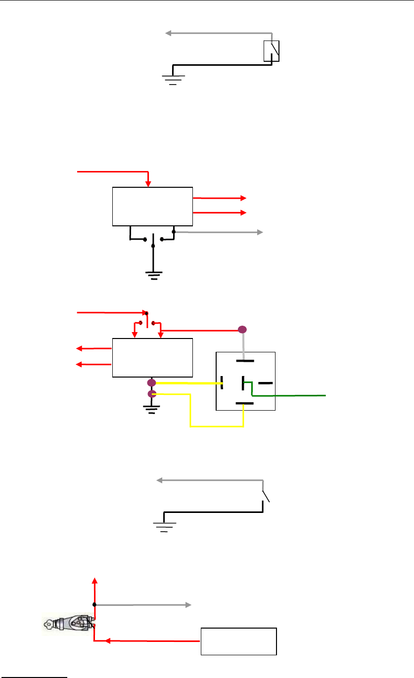
For Output Ports
1. Fuel-cut or Engine-cut
Relay for lock control
Power for Relay
lock
unlock
Input 1 or Input 2 or Input 3
Lock switch
Power for lock Motor
30
85
86 Green
Relay
Relay for lock control
Power for Relay
lock unlock Input 1 or Input 2 or Input 3
White
Lock switch
Power for lock Motor
Input 1 or Input 2 or Input 3 White sensor likes SOS Button
Input 1 or Input 2 or Input 3 White SOS Button
Ignition Switch
Input 4 or Input 5
Battery positive
Power for ignition
TOPTEN GPS
- 8 -
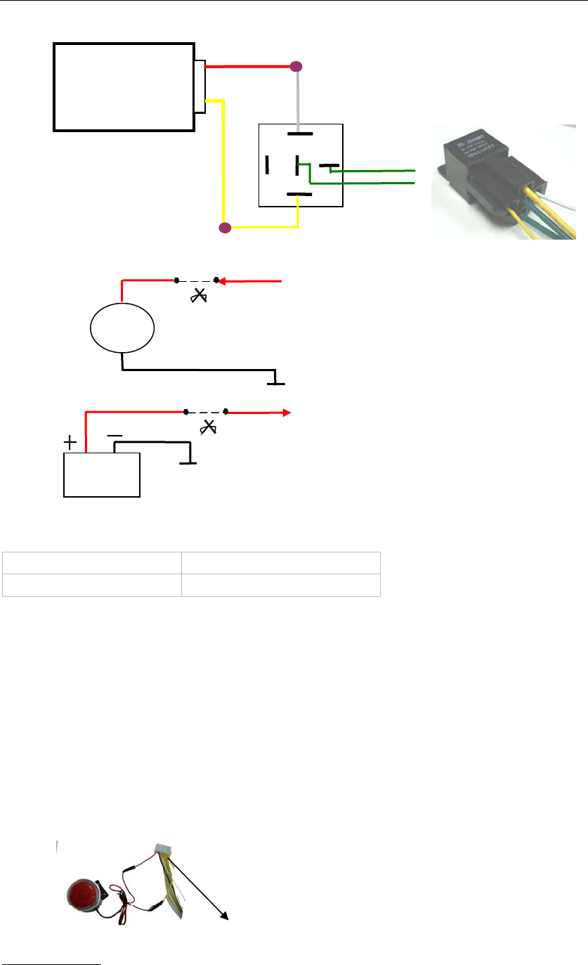
(1) Connect the relay as above picture shows and calculate the correct VCC value according to the
relay parameter to make sure to comply with the following requirements:
Input Voltage to Output Must < 45V
input Current to Output Must < 500mA
Normally two green wires are connected solidly, when output 1 is open (be negative), two
green wires will disconnect, so the power is cut.
(2) Send the following SMS to open Output1(cut engine or cut fuel)
W<password>,020,1,1
(3) Send the following SMS to close Output1:
W<password>,020,1,0
2. Connecting with Car Alarm
When the output that connected to the Alarm is open, the Alarm will work. Please refer to the <SMS
Command List> for the command.
For Analog Inputs
The input must be voltage and input voltage: 0~6V. Please refer to <GPRS Communication
Motor
P1 P2
Fuel pump power supply loop
Fuel pump Motor
Battety
P1
Engine ignition loop
Power for Motor
Power for ignition
P2
Output 2 or Output 3 or Output 4 or Output5
Alarm
Blue cable linked with relay
for engine-cut or fuel-cut
30
85
86
P1
P2
VCC
Yellow
White
Green
Relay
TOPTEN GPS
- 9 -
Protocol >for the AD1 and AD2 datas. For example:
094506.000,A,2232.5412,N,11404.6919,E,0.00,,290709,,*12|1.7|110|0000|0002,0267
As above, 0x0002 is AD1, 0x0267 is AD2.
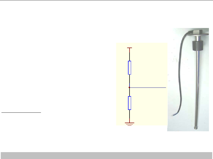
Fuel sensor input for example:
Our fuel sensor is resistance type sensor, output
resistance:0-200ohm.
As the right circuit, if VCC is 12V, R should
be 200ohm and if VCC is 24V then R should
be 600ohm to make the input range to AD1 or AD2
is 0-6V.
Below formula is for calculate the fuel percent left
(it only suit to above fuel sensor):
1/ 2
1024 %
1024
AD AD
Value−
Note: the Value must be converted to decimal,
for example: 0x0267 is 615 in decimal.
5 SMS Command
TK310 will only accept commands from a user with the correct password. Commands with wrong
password are ignored. The default password is 000000.
5.1 Basic SMS Commands
5.1.1 Position Report
To know the location of your TK310, send an SMS or make a telephone call directly to TK310 and it will
report its location by SMS.
Command: W<password>,<000>
Notes: The default password is 000000.
Example:
SMS sent: W000000,000
SMS received:
Latitude = 22 32 36.63N Longitude = 114 04 57.37E, Speed = 2.6854Km/h, 2008-12-24,01:50
To get TK310’s position by another easier way:
(a) Call TK310 using your mobile phone.
(b) After listening to the ring for 10 - 20 seconds, hang up the phone.
(c) Then after 20 second, your mobile phone will receive a position SMS.
5.1.2 Set Interval for Automatic Timed Report
Description: Automatic timed reports will be sent to your mobile phone according to the time interval you
set.
Command: W<password>,002,XXX
Notes: XXX is the interval in minute. If XXX=000 it will stop tracking
fuel sensor
0-200
R
VCC
AD1 or AD2

TOPTEN GPS
- 10 -
Example:
SMS sent: W000000,002,005
SMS received: Set Timer Ok/005
TK310 will then report its location by SMS every 5 minutes.
5.1.3 Stop Automatic Timed Report
Description: Automatic timed reports will stop once TK310 receives stop command.
Command: W<password>,002,000
Example:
SMS sent: W000000,002,000
SMS received: Set Timer Ok/000
TK310 will stop automatic timed report
For more detailed SMS commands please go to Chapter 8 - SMS Command List
5.2 GPRS Settings by SMS
Tracking via GPRS, you should set IP, Port and APN for TK310.
Ensure that your SIM card in TK310 supports GPRS connection prior to setting.
5.2.1 Set ID for TK310
Command: W<password>,010,ID
Note: Tracker ID must not over 14 digits.
Example: W000000,010,123456789
TK310 will then reply with an SMS (‘Set SIM Ok/123456789’) to confirm this setting.
5.2.2 Set APN
Command: W<password>,011,APN,APN Name,APN Password
Note: If no APN name and password required, input APN only.
Example: W000000,011,CMNET
TK310 will reply with an SMS (like ‘Set APN Ok/CMNET’) to confirm this setting.
5.2.3 Set IP Address and Port
Command: W<password>,012,IP,PORT
Example: W000000,012,202.116.11.12,8000
TK310 will then reply an SMS (‘Set IP Ok /202.116.11.12,8000’) to confirm this setting.
5.2.4 Set Time Interval for Sending GPRS Packet
Command: W<password>,014,time interval(in unit of 10 seconds)
Example: W000000,014,00003
TK310 will send GPRS packet every 30 seconds
5.2.5 Enable GPRS Tracking Function
Command: W<password>,013,X
X=0, to turn off GPRS tracking function (default);
X=1, to set TCP
TOPTEN GPS
- 11 -
X=2, to set UDP
Example: W000000,013,1
TK310 will reply with an SMS to confirm this setting.
For more information regarding of bulk configuration by USB cable please refer to < GPS Tracker
Parameter Editor>.
For more information regarding GPRS settings please refer to <GPRS Communication Protocol >.
If you are using GpsGate Software, please contact us for writing GpsGate protocol before
delivery.
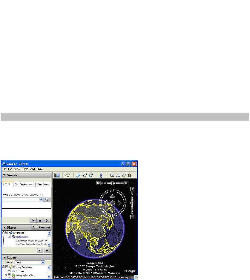
6 Tracking on Map
Download Google Earth from http://earth.google.com/
Start the Google Earth (For more information about Google Earth please refer to http://earth.google.com/)
as the following picture shows:
Input the latitude and longitude that you receive from the tracker by SMS and click the search button.
Google Earth will display the location for you.
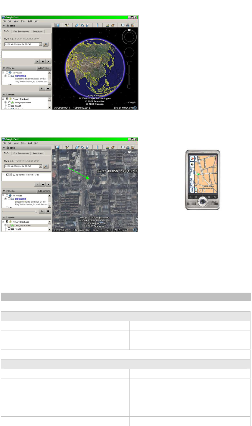
Example:
When you receive:
Latitude = 22 32 40.05N
Longitude = 114 04 57.74E
Type as the following picture shows:
(Note: you should input the latitude and longitude as: 22 32 40.05N 114 04 57.74E)
TOPTEN GPS
- 12 -
Now you can find the location of your tracker:
Or you can start the Internet Explorer and connect to http://maps.google.com for displaying the location.
Or you can use local map software on PDA or car navigation device to input the coordinates.
7 Troubleshooting
Problem: Unit will not turn on
Possible Cause: Resolution:
Wiring was not connected properly Check and make sure wiring connection is in order.
Battery needs charging Recharge battery
Problem: Unit will not respond to SMS
Possible Cause: Resolution:
GSM antenna was not installed properly Make TK310 connected to GSM network.
GSM Network is slow Wait for SMS. Some GSM networks slow down during
peak time or when they have equipment problems.
Unit is sleeping Cancel sleeping mode
Wrong password in your SMS or wrong SMS format Write correct password or SMS format

TOPTEN GPS
- 13 -
The SIM in TK310 has run out of credit Replace or top up the SIM card
No SIM card Insert working SIM card. Check in phone that the SIM
can send SMS message.
SIM card has expired Check in phone that the SIM can send SMS
message. Replace SIM card if needed.
SIM has PIN code set Remove PIN code by inserting SIM in you phone and
deleting the code.
SIM is warped or damaged Inspect SIM, clean the contacts. If re-inserting does
not help try another to see if it will work.
Roaming not enabled If you are in a different country your SIM account
must have roaming enabled.
Problem: SMS received starts with ‘Last…’
Possible Cause: Resolution:
Unit does not have clear view of the sky Move the antenna of the unit to a location where the
sky is visible.
TK310 is in an inner place Wait for the target to come out
Battery is low Recharge the unit and the GPS will start working.
8 SMS Command List
(Remarks: ****** is user’s password, and the default password is 000000)
Description Command Remarks
Get current location W******,000 Get current location of TK310
Change user’s password W******,001,###### ****** is old password
###### is new password
Set interval for automatic
timed report
W******,002,XXX XXX is the interval in minute. If
XXX=000 it will stop tracking
Set preset phone number
for SOS button
W******,003,F,P,T F=0, to turn off this function;
F=1, to send SMS;
As SOS button is linked to IN1, P=1.
T: Preset phone number. Max 16 digits
Set low power alert
When TK310 voltage is
lower than the preset value,
it will send one low power
alert to the SOS preset
number.
W******,004,X X (voltage preset value)
=0 , to turn off this function
=1, <3.3V send SMS alert
=2 , <3.4V send SMS alert
=3 , <3.5V send SMS alert (default )
=4 , <3.6V send SMS alert
=5 , <3.7V send SMS alert

TOPTEN GPS
- 14 -
Set over speed alert
When TK310 speeds higher
than the preset value, it will
send an SMS to the SOS
preset number.
W******,005,XX XX (the preset value of speed)
=00 , to turn off this function
=[01, 20] (unit: 10Km/h)
For example, W000000,005,08, it will
sent alert when it is over 80Km/h
Set Geo-fence alert
When the TK310 moves out
of preset scope, it will send
one Geo-fence SMS to the
SOS preset number.
W******,006,XX XX ( preset distance to original place )
=00, close
=01, 30m
=02, 50m
=03, 100m
=04, 200m
=05, 300m
=06, 500m
=07, 1000m
=08, 2000m

TOPTEN GPS
- 15 -
Extend Settings W******,008,ABCDEFG### A=0, turn off the function of sending an
SMS location report to the authorized
phone number when it makes a call to
TK310.
A=1, turn on the function of sending an
SMS location report to the authorized
phone number when it makes a call to
TK310.
B=0, location data of NMEA 0183
GPRMC will be interpreted into normal
text for easy reading.
For example:
Longitude = 114 degree - 04 cent
-57.74 second
Latitude = 22 degree -32 cent -40.05
second
B=1, location data complies with NMEA
0183 GPRMC protocol.
For example:
$GPRMC,072414.000,V,3114.3763,N,
12131.3255,E,0.00,0.00,050805,*00
C=0, turn off the function to
automatically hang up an incoming call.
C=1, turn on the function to
automatically hang up an incoming call
after 4 - 5 rings.
D=0, Turn off the function of sending an
SMS when TK310 is turned on.
D=1, Turn on the function of sending an
SMS to SOS number when TK310 is
turned on.
E=0, reserved
E=1, TK310 shuts down automatically
when the power voltage lower than 3V.
F=0, Turn off the alert when TK310
enters GPS blind area.
F=1, Turn on the alert when TK310
enters GPS blind area. SMS is to be
sent to SOS number
G=0, LED light works normally
G=1, LED light stops flashing when
TK310 working.
### is the ending character
(default value is: ABCDEFG=1000100 )

TOPTEN GPS
- 16 -
Presetting by SMS for GPRS tracking (Ensure that your SIM card supports GPRS connection prior to setting)
Set ID for TK310 W******,010,ID Tracker ID must not over 14 digits.
Set APN W******,011,APN,APNName,APN
Password
If no APN name and password
required, just insert APN only;
APN defaulted as ‘CMNET’;
APN + APN name + password not over
39 characters.
Set IP Address and Port W******,012,IP, Port IP: xxx.xxx.xxx.xxx Port: [1,65534]
Enable GPRS Tracking
Function
W******,013,X X=0, close GPRS (default);
X=1, enable TCP
X=2, enable UDP
Set Time Interval for
Sending GPRS Packet
W******,014,XXXXX XXXXX should be in five digitals and in
unit of 10 seconds.
XXXXX=00000, to close this function;
XXXXX=00001~65535, time interval for
sending GPRS packet and in unit of 10
seconds.
For more information regarding GPRS settings please refer to <GPRS Communication Protocol>
Output Control W******,020,P,F P =1, Out1
=2, Out2
=3, Out3
=4, Out4
=5, Out5
F =0, to close the output
=1, to open the output
Output Control (Safe
mode)
This function is achievable
when the speed is below
10km/h and GPS is
available.
W******,120,ABCDE ABCDE represents Out1, Out2, Out3,
Out4, and Out5 respectively.
If A or B or C or D or E,
=0, to close the output
=1, to open the output
=2, to remain previous status
Set sleep mode
for saving power
W******,021,XX### XX=00 turn off sleep mode
XX=01 sleep mode
XX=02 deep sleep mode
### is the ending character
Set power saving mode
when TK310 is inactive
(In power saving mode, GPS
stops working. GSM enters
standby mode and stop
sending out message until it
is activated by an SMS or an
incoming call)
W******,026,XX XX=00, to turn off this function
XX=01~99, to set this function. It is in
unit of minute.
Example:
If XX=10, TK310 will enter power
saving mode after it is immobile for 10
minutes.

TOPTEN GPS
- 17 -
Set phone number for
wiretapping
W******,030,T T is the telephone number for
wiretapping and max. 16 digits
Set interval for logging
(Note: this interval is not
relevant to the interval of
continuous tracking)
W******,031,X X=0, to turn off this function
X=[1, 65535] to set interval in second.
For example, W000000,031,60, TK310
will store location data every 60
seconds.
Set time zone difference W******,032,T T=0, to turn off this function
T=[1, 65535] to set time difference in
minute to GMT. Default value is GMT
For those ahead of GMT, just input the
time difference in minute directly. For
example, W000000,032,120
‘-‘is required for those behind GMT. For
example, W000000,032,-120.
Set character for SOS alert
message
W******,033,1,Char Char is the character in SOS message
and max 32 characters
Get version and serial
number
W******,600 To get version and serial number of
current firmware
Get IMEI W******,601 To get IMEI
This device complies with Part 15 of the FCC Rules. Operation
is subject to the following two conditions: (1) this device may not cause harmful
interference, and (2) this device must accept any interference received, including
interference that may cause undesired operation.
This equipment complies with FCC RF radiation exposure limits set forth for an
uncontrolled environment. This device and its antenna must not be co-located or
operating in conjunction with any other antenna or transmitter.
“To comply with FCC RF exposure compliance requirements.The antennas used for this
transmitter must be installed to provide a separation distance of at least 30 cm from all
persons and must not be co-located or operating in conjunction with any other antenna or
transmitter.”
Changes or modifications not expressly approved by the party responsible for compliance
could void the user's authority to operate the equipment
FCC ID: X3U-TK310
Model No.: TK310
Manufacturer: Topten electronics Technology Limited