TOPICON MDT GPS User Manual Business Proposal
TOPICON HK LIMITED GPS Business Proposal
UserManual.wiki
>
TOPICON
>
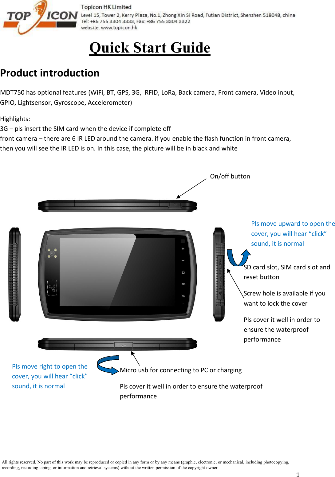
MDT User Manual
User Manual
Navigation menu
Upload a User Manual
Namespaces
Wiki Guide
HTML
PDF
Info
Views
User Manual
Discussion / Help
Navigation